ETSI TS 102 622
V11.0.0
(2011-09)
Smart Cards;
UICC - Contactless Front-end (CLF) Interface;
Host Controller Interface (HCI)
(Release 11)
Reference RTS/SCP-THCIvb00
Keywords smart card
ETSI
650 Route des Lucioles
F-06921 Sophia Antipolis Cedex - FRANCE
Tel.: +33 4 92 94 42 00 Fax: +33 4 93 65 47 16 Siret N° 348 623 562 00017 - NAF 742 C Association à but non lucratif enregistrée à la
Sous-Préfecture de Grasse (06) N° 7803/88
Important notice
Individual copies of the present document can be downloaded from: http://www.etsi.org
The present document may be made available in more than one electronic version or in print. In any case of existing or perceived difference in contents between such versions, the reference version is the Portable Document Format (PDF). In case of dispute, the reference shall be the printing on ETSI printers of the PDF version kept on a specific network drive
within ETSI Secretariat.
Users of the present document should be aware that the document may be subject to revision or change of status. Information on the current status of this and other ETSI documents is available at
http://portal.etsi.org/tb/status/status.asp
If you find errors in the present document, please send your comment to one of the following services: http://portal.etsi.org/chaircor/ETSI_support.asp
Copyright Notification
No part may be reproduced except as authorized by written permission. The copyright and the foregoing restriction extend to reproduction in all media.
© European Telecommunications Standards Institute 2011. All rights reserved.
DECTTM, PLUGTESTSTM, UMTSTM and the ETSI logo are Trade Marks of ETSI registered for the benefit of its Members.
3GPPTM and LTE™ are Trade Marks of ETSI registered for the benefit of its Members and of the 3GPP Organizational Partners.
Contents
Intellectual Property Rights ... 6
Foreword ... 6
1 Scope
... 7
2 References
... 7
2.1 Normative references ... 7
2.2 Informative references ... 8
3 Definitions,
symbols and abbreviations ... 8
3.1 Definitions ... 8 3.2 Symbols ... 8 3.3 Abbreviations ... 8 3.4 Coding conventions ... 9
4 HCI
architecture
... 9
4.1 Overview ... 9 4.2 Hosts ... 10 4.3 Gates ... 10 4.4 Pipes ... 11 4.5 Registries ... 125 HCP
... 13
5.1 HCP packets ... 13 5.2 HCP message structure ... 13 5.3 Message fragmentation ... 146 Instructions
... 15
6.1 Commands ... 15 6.1.1 Overview ... 15 6.1.2 Generic commands ... 16 6.1.2.1 ANY_SET_PARAMETER ... 16 6.1.2.2 ANY_GET_PARAMETER ... 16 6.1.2.3 ANY_OPEN_PIPE ... 16 6.1.2.4 ANY_CLOSE_PIPE ... 17 6.1.3 Administration commands ... 17 6.1.3.1 ADM_CREATE_PIPE ... 17 6.1.3.2 ADM_NOTIFY_PIPE_CREATED ... 17 6.1.3.3 ADM_DELETE_PIPE ... 18 6.1.3.4 ADM_NOTIFY_PIPE_DELETED ... 18 6.1.3.5 ADM_CLEAR_ALL_PIPE ... 18 6.1.3.6 ADM_NOTIFY_ALL_PIPE_CLEARED ... 18 6.2 Responses ... 19 6.3 Events ... 207 GATES
... 20
7.1 Management gates ... 22 7.1.1 Administration gates ... 227.1.1.1 Host controller administration gate ... 22
7.1.1.2 Host administration gate ... 22
7.1.2 Link management gate ... 23
7.1.2.1 Host controller link management gate... 23
7.1.2.2 Host link management gate ... 23
7.1.3 Identity management gate ... 24
7.1.4 Loop back gate ... 24
7.2 Generic gates ... 24
8 HCI
procedures
... 25
8.1.1 Pipe creation ... 25
8.1.2 Pipe deletion ... 27
8.1.3 Clear all Pipes ... 28
8.2 Registry access ... 28
8.3 Host and Gate discovery ... 29
8.4 Session initialization... 30
8.5 Loop back testing ... 31
9 Contactless
card emulation ... 32
9.1 Overview ... 32
9.2 Void ... 34
9.3 Gates ... 34
9.3.1 Void ... 34
9.3.2 Identity management gate ... 34
9.3.3 Card RF gates ... 34 9.3.3.1 Overview ... 34 9.3.3.2 Commands ... 34 9.3.3.3 Events ... 34 9.3.3.3.1 EVT_SEND_DATA ... 35 9.3.3.4 Registry ... 35 9.3.3.4.1 RF technology type A ... 35 9.3.3.4.2 RF technology type B ... 37 9.3.3.4.3 RF technology type B' ... 38
9.3.3.4.4 RF technology Type F (ISO/IEC 18092 212 kbps/424 kbps card emulation only) ... 38
9.3.4 Card application gates ... 39
9.3.4.1 Overview ... 39 9.3.4.2 Commands ... 39 9.3.4.3 Events ... 39 9.3.4.3.1 EVT_FIELD_ON ... 40 9.3.4.3.2 EVT_CARD_DEACTIVATED ... 40 9.3.4.3.3 EVT_CARD_ACTIVATED ... 40 9.3.4.3.4 EVT_FIELD_OFF ... 40 9.3.4.3.5 EVT_SEND_DATA ... 40 9.3.4.4 Registry ... 40 9.4 Procedures ... 41
9.4.1 Use of contactless card application ... 41
9.4.2 Non ISO/IEC 14443-4 type A... 42
9.4.3 Type B' RF technology ... 42
9.4.4 Type F RF technology ... 42
9.4.5 Update RF technology settings ... 43
9.4.6 Identity check ... 43
10 Contactless reader ... 44
10.1 Overview ... 44 10.2 Reader RF gates ... 45 10.2.1 Overview ... 45 10.2.2 Command ... 45 10.2.2.1 WR_XCHG_DATA ... 45 10.2.3 Registries ... 4610.2.3.1 Type A reader RF gate ... 46
10.2.3.2 Type B reader RF gate ... 47
10.2.4 Events ... 47
10.2.4.1 EVT_READER_REQUESTED ... 47
10.2.4.2 EVT_END_OPERATION ... 47
10.2.5 Responses ... 48
10.3 Reader application gates ... 48
10.3.1 Overview ... 48 10.3.2 Command ... 48 10.3.3 Registry ... 48 10.3.4 Events ... 48 10.3.4.1 EVT_TARGET_DISCOVERED ... 48 10.4 Procedures ... 49
10.4.1 Use of contactless reader application ... 49
11 Connectivity ... 50
11.1 Overview ... 50 11.2 Connectivity gate ... 50 11.2.1 Commands ... 50 11.2.1.1 PRO_HOST_REQUEST ... 50 11.2.2 Events ... 51 11.2.2.1 EVT_CONNECTIVITY ... 51 11.2.2.2 Void... 51 11.2.2.3 EVT_OPERATION_ENDED ... 51 11.2.2.4 EVT_TRANSACTION ... 51 11.2.3 Registry ... 5111.3 Connectivity application gate ... 51
11.3.1 Commands ... 51
11.3.2 Events ... 52
11.3.2.1 EVT_STANDBY ... 52
11.3.3 Registry ... 52
11.4 Procedures ... 52
11.4.1 Use of connectivity gate ... 52
Annex A (informative):
Change history ... 54
Intellectual Property Rights
IPRs essential or potentially essential to the present document may have been declared to ETSI. The information pertaining to these essential IPRs, if any, is publicly available for ETSI members and non-members, and can be found in ETSI SR 000 314: "Intellectual Property Rights (IPRs); Essential, or potentially Essential, IPRs notified to ETSI in respect of ETSI standards", which is available from the ETSI Secretariat. Latest updates are available on the ETSI Web server (http://ipr.etsi.org).
Pursuant to the ETSI IPR Policy, no investigation, including IPR searches, has been carried out by ETSI. No guarantee can be given as to the existence of other IPRs not referenced in ETSI SR 000 314 (or the updates on the ETSI Web server) which are, or may be, or may become, essential to the present document.
Foreword
This Technical Specification (TS) has been produced by ETSI Technical Committee Smart Card Platform (SCP). The contents of the present document are subject to continuing work within TC SCP and may change following formal TC SCP approval. If TC SCP modifies the contents of the present document, it will then be republished by ETSI with an identifying change of release date and an increase in version number as follows:
Version x.y.z where:
x the first digit:
0 early working draft;
1 presented to TC SCP for information; 2 presented to TC SCP for approval;
3 or greater indicates TC SCP approved document under change control.
y the second digit is incremented for all changes of substance, i.e. technical enhancements, corrections, updates, etc.
1 Scope
The present document specifies a logical interface that enables contactless applications hosted on the UICC. The present document covers the configuration where the one host is embedded in the UICC which is connected to the host
controller embedded in the CLF. The interface is specified in two parts:
• the HCI core as described in the first part of the present document (clauses 4 to 8), specifies an application independent logical interface; and
• the contactless platform as described in the second part of the present document (clauses 9 to 11) specifies an implementation of the HCI core for contactless applications using the UICC and the CLF.
Lower layer protocols that support the HCI like the SWP specified in TS 102 613 [2] are out of the scope of the present document.
2 References
References are either specific (identified by date of publication and/or edition number or version number) or
non-specific. For specific references, only the cited version applies. For non-specific references, the latest version of the reference document (including any amendments) applies.
• In the case of a reference to a TC SCP document, a non specific reference implicitly refers to the latest version of that document in the same Release as the present document.
Referenced documents which are not found to be publicly available in the expected location might be found at
http://docbox.etsi.org/Reference.
NOTE: While any hyperlinks included in this clause were valid at the time of publication ETSI cannot guarantee their long term validity.
2.1 Normative
references
The following referenced documents are necessary for the application of the present document. [1] Void.
[2] ETSI TS 102 613: "Smart Cards; UICC - Contactless Front-end (CLF) Interface; Part 1: Physical and data link layer characteristics".
[3] ETSI TS 102 223: "Smart Cards; Card Application Toolkit (CAT)".
[4] ISO/IEC 18092: "Information technology - Telecommunications and information exchange between systems - Near Field Communication - Interface and Protocol (NFCIP-1)".
[5] ISO/IEC 14443-2: "Identification cards - Contactless integrated circuit(s) cards - Proximity cards - Part 2: Radio frequency power and signal interface".
[6] ISO/IEC 14443-3: "Identification cards - Contactless integrated circuit(s) cards - Proximity cards - Part 3: Initialization and anticollision".
[7] ISO/IEC 14443-4: "Identification cards - Contactless integrated circuit cards - Proximity cards - Part 4: Transmission Protocol".
[8] ISO/IEC 7816-4: "Identification cards - Integrated circuit cards - Part 4: Organization, security and commands for interchange".
[9] ETSI TS 101 220: "Smart Cards; ETSI numbering system for telecommunication application providers".
2.2 Informative
references
The following referenced documents are not necessary for the application of the present document but they assist the user with regard to a particular subject area.
[i.1] JIS X 6319-4:2005: "Specification of implementation for integrated circuit(s) cards -- Part 4: High speed proximity cards".
3
Definitions, symbols and abbreviations
3.1 Definitions
For the purposes of the present document, the following terms and definitions apply:
gate: entry point towards a service that is operated inside a host
host controller: host that is also responsible for managing a host network host network: network of two or more hosts
host: logical entity that operates one or more service(s)
pipe: logical communication channel between two gates from different hosts
registry: data related to a gate that are stored as a collection of parameter - value pairs
service: collection of related atomic functions in a host for management purposes or for performing contactless actions
3.2 Symbols
For the purpose of the present document the following symbols apply:
GID gate identifier
HID host identifier
PID pipe identifier
PIPEx a pipe with a PID value equal to x
3.3 Abbreviations
For the purposes of the present document, the following abbreviations apply: AFI Application Family Identifier
AID Application IDentifier
APDU Application Protocol Data Unit
BER-TLV Basic Encoding Rules - Tag, Length, Value
C-APDU Command APDU
CB Chaining Bit
CLF ContactLess Front-end
CLT ContactLess Tunnelling
HCI Host Controller Interface HCP Host Controller Protocol NFC Near Field Communication PA PreAmble PCD Proximity Coupling Device
PICC Proximity Card
R-APDU Response APDU
RF Radio Frequency
RO Read-Only RW Read/Write
SAK Select AcKnowledge
SWP Single Wire Protocol WO Write-Only
3.4 Coding
conventions
For the purposes of the present document, the following coding conventions apply:
• All lengths are presented in bytes, unless otherwise stated. Each byte is represented by bits b8 to b1, where b8 is the most significant bit and b1 is the least significant bit. In each representation, the leftmost bit is the most significant bit.
• Hexadecimal values are specified between single quotes, e.g. '1F'. In a sequence of bytes, byte 1 is the leftmost byte.
• All bytes specified as RFU shall be set to '00' and all bits specified as RFU shall be set to 0.
4 HCI
architecture
4.1 Overview
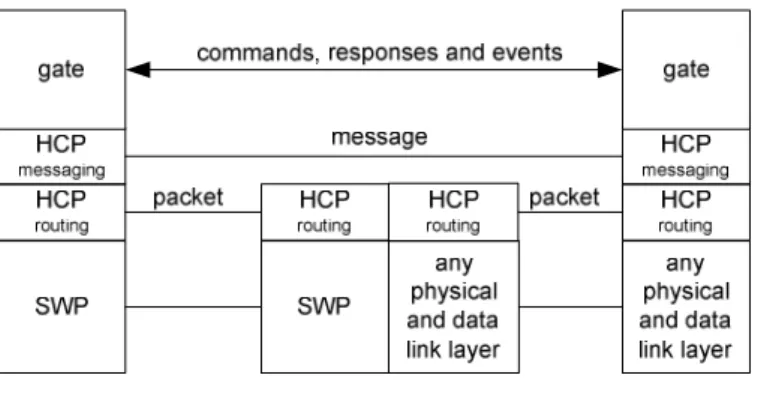
A valid host network has a star topology where one or more hosts physically connect to a host controller. The HCI defines the interface between hosts. More specifically the HCI has three levels:
• a collection of gates that exchange commands, responses and events; and • an HCP messaging mechanism; and
• an HCP routing mechanism that may optionally segment messages when required. Figure 1 illustrates the HCP stack in a possible host network.
Figure 1
NOTE: For clarity only two gates are shown. In particular the host controller also has gates that connect via HCP to other hosts.
For proper operation, the HCP requires underlying data link layers to have the following properties:
• The data link layer (e.g. SWP) shall be error free and the order of the received/sent data shall be respected. • The data link layer provides its own data flow control.
• The data link layer shall deliver packets of the upper layer up to a maximum size specific to the data link layer. • The data link layer shall report the size of each received packet to its upper layer.
4.2 Hosts
The identity of a host is coded in a byte. Table 1 lists the reserved values for the host identifier, HID. Table 1 Host HID host controller '00' terminal host '01' UICC host '02' RFU '03' to 'BF' Proprietary 'C0' to 'FF'
In the present document, the generic term "host" is used to refer to any logical host (e.g. terminal host, UICC host) excluding the host controller.
4.3 Gates
A gate provides an entry point to a service that is operated inside a host. The HCP enables gates from different hosts to exchange messages. There are two types of gates:
• Management gates that are needed for the management of the host network.
• Generic gates that are not related to the management of the host networks. Only the generic aspects of these gates are defined in the HCI core.
The type of a gate is identified by a gate identifier. Gate identifiers are listed in table 2 and are either unique within the scope of a host ('10' to 'FF'), or their values refer to the same gate type for every host ('00' to '0F').
Table 2
Gate GID
reserved for proprietary use '00' to '03' loop back gate '04' identity management gate '05'
RFU '06' to '0F'
Host specific '10' to 'EF' reserved for proprietary use 'F0' to 'FF'
Host specific gates for hosts defined in the present document (including RFU ones) are reserved for use in the present document.
The following rules apply to hosts and gates:
• all hosts and the host controller shall have one administration gate (see clause 7.1.1); and
• all hosts may have one link management gate (see clause 7.1.2) and the host controller shall have one link management gate; and
• all hosts and the host controller shall have one identity management gate (see clause 7.1.3); and • all hosts and the host controller shall have one loop back gate (see clause 7.1.4); and
4.4 Pipes
A pipe is a logical communication channel between two gates. There are two types of pipes:
• static pipes that are always available, i.e. they do not need to be created and cannot be deleted; and • dynamic pipes that can be created and deleted.
The state of a pipe is either open or closed. The state shall remain persistent if the hosts are powered down and up again. It shall also remain persistent if a host is temporarily removed from the host network and was not replaced by a different device in the meantime. The state of a dynamic pipe after creation and the initial state of a static pipe shall be closed. The pipe identifier, PID, is 7 bits long. The value of PID is used in the header of HCP packets as routing information (see clause 5.1). For static pipes the pipe identifiers are predefined with values as defined in table 3. For dynamic pipes, pipe identifiers are dynamically allocated by the host controller.
Table 3
PID Pipe ending at: Pipe type
'00' link management gate static '01' administration gate '02' to '6F' other gates dynamic '70' to '7F' RFU
The following rules apply to gates and pipes:
• a static pipe always connects a gate of a host to a gate of the host controller; • a dynamic pipe connects two gates from different hosts; and
• static and dynamic pipes connect to different types of gates; see table 3 for the mapping; and • dynamic pipe identifiers shall be unique in the host network.
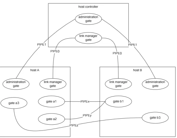
Figure 2 illustrates hosts and gates in a valid host network.
NOTE: For clarity the identity management and loop back gates are not shown.
Figure 2
4.5 Registries
With every gate a registry template may be associated that defines parameters that are related to the gate. Parameters are identified by parameter identifiers consisting of one byte. Parameter identifiers are unique within the scope of the gate. For all gates defined in the present document, parameter identifiers in the range of '00' to 'EF' are reserved for use in the present document. Parameter identifiers in the range of 'F0' to 'FF' may be used for proprietary purposes.
A new instance of the registry is created for every pipe that connects to the gate. Upon pipe creation all registry parameters with access rights Read-write (RW) or Write-only (WO) shall be set to their default values. Read-only (RO) parameters shall be set by the entity managing the registry to an appropriate value which may differ from the default values.
A host is responsible for managing its associated registries. The persistence of a registry and the default values for parameters shall be indicated with each registry description.
5 HCP
5.1 HCP
packets
Using the data link layer hosts exchange packets with the host controller. The format of a packet is defined in figure 3.
CB
pID
bit b8 bits b7 to b1header
n bytes
message
Figure 3The interpretation of the fields in the packet header shall be the following:
• CB is the chaining bit and its value is equal to 1 except when message fragmentation is used (see clause 5.3); and
• PID specifies the pipe identifier.
The host controller uses the value of PID to forward a packet to the destination host. The destination host forwards the packet to the destination gate. Using these mechanisms any two gates that are connected by a pipe can exchange messages.
The host controller shall verify that the pipe identifier is used by a host involved in the creation of the pipe. The size of a message is application specific. The message structure is described in clause 5.2.
5.2
HCP message structure
A message carries one instruction and optional data as defined in figure 4.
TYPE INSTRUCTION
b8, b7 b6 to b1
header
data
n bytes
Figure 4 The meaning of the fields in the message header is the following:
• TYPE identifies the type of instruction; and • INSTRUCTION identifies the instruction.
The following types of instructions are defined: • commands (type value 0);
• events (type value 1); and
• responses to commands (type value 2).
Type value 3 is RFU. The instruction value further qualifies the command, event or response. All three types may carry data.
For instructions the following rules apply:
• An event is defined within the scope of the gate that accepts the events. • A command is defined within the scope of the gate that accepts the command. • A response is defined within the scope of its associated command.
A gate shall only accept a command or an event on a pipe when the state of that pipe is open unless otherwise stated. A gate shall not send a command or event on a pipe when it is waiting for a response to a previous command on that pipe unless otherwise stated. A gate shall interpret incoming events and commands even while it is waiting for a response to a previously sent command.
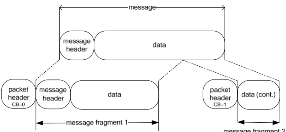
5.3 Message
fragmentation
Message fragmentation shall be used when the size of the message is larger than supported by the underlying data link layer. Messages shall be fragmented according to the following rules:
• All message fragments shall have a packet header.
• The value of the chaining bit in the packet header is equal to 0, except for the packet with the last fragmented message where the value shall be 1.
• Only the first message fragment shall contain a message header. Figure 5 illustrates how one message is split into two fragments.
Figure 5
The source gate is responsible for fragmenting messages. The destination gate is responsible for rebuilding the message from the fragmented messages.
If a reset of the underlying data link layer occurs, fragments of a partially received message shall be discarded and a partially sent message shall be re-sent from the beginning.
6 Instructions
The structure of the data field for the instructions is defined in the tables in this clause as the sequence of fields in the tables.
6.1 Commands
6.1.1 Overview
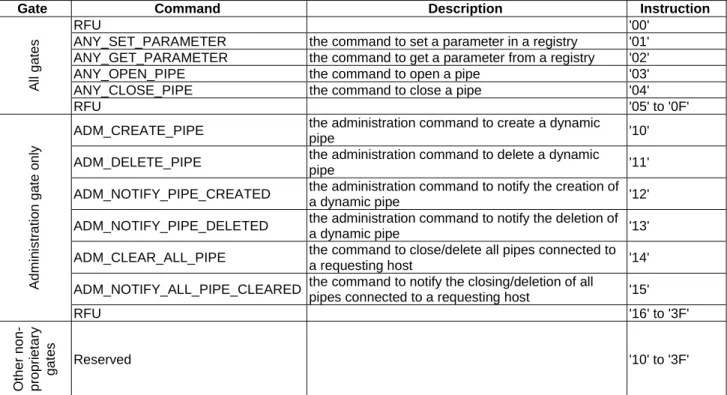
Table 4 lists all the commands that will be described in clauses 6.1.2 and 6.1.3. The interpretation of all the commands shall be the same for all gates specified in clause 7. There are two groups of commands:
• generic commands are applicable to all gates; and
• administration commands needed for the management of the host network. Table 4
Gate Command Description Instruction
All ga
tes
RFU '00'
ANY_SET_PARAMETER the command to set a parameter in a registry '01' ANY_GET_PARAMETER the command to get a parameter from a registry '02'
ANY_OPEN_PIPE the command to open a pipe '03'
ANY_CLOSE_PIPE the command to close a pipe '04'
RFU '05' to '0F' Admin istr a tio n ga te o n ly
ADM_CREATE_PIPE the administration command to create a dynamic
pipe '10'
ADM_DELETE_PIPE the administration command to delete a dynamic
pipe '11'
ADM_NOTIFY_PIPE_CREATED the administration command to notify the creation of
a dynamic pipe '12'
ADM_NOTIFY_PIPE_DELETED the administration command to notify the deletion of
a dynamic pipe '13'
ADM_CLEAR_ALL_PIPE the command to close/delete all pipes connected to
a requesting host '14'
ADM_NOTIFY_ALL_PIPE_CLEARED the command to notify the closing/deletion of all
pipes connected to a requesting host '15'
RFU '16' to '3F' O ther non-propri e tary gate s Reserved '10' to '3F'
For every command the following information is provided: • a description of the command; and
• a list of parameters for the command; and
• the response on successful completion of the command (with optional parameters). The mapping of possible response codes is given in clause 6.3.
6.1.2 Generic
commands
6.1.2.1 ANY_SET_PARAMETER
The command ANY_SET_PARAMETER is used to write a parameter value into a gate registry. The command parameters are as follows:
Table 5
Description Length
index of the parameter in the registry 1
value of the parameter; the length and content of the parameter depend on the registry N
When successful the host shall respond with ANY_OK without any parameters.
6.1.2.2 ANY_GET_PARAMETER
The command ANY_GET_PARAMETER is used to read a parameter value from a gate registry. The command parameters are as follows:
Table 6
Description Length
index of the parameter in the registry 1
When successful the host shall respond with ANY_OK with parameter as follows: Table7
Description Length
value of the parameter; the length and content of the parameter depends on the registry
N
6.1.2.3 ANY_OPEN_PIPE
The command ANY_OPEN_PIPE allows a host to open a pipe. NOTE: This command is sent over a closed pipe. The command has no parameters.
If the destination host is the host controller, and if the pipe is successfully opened the host controller shall send an ANY_OK response without any parameter.
For hosts other than the host controller, when the pipe is successfully opened, the destination host shall send an ANY_OK response with a parameter as follows:
Table 8
Description Length
Number of pipes already open on this gate before the execution of the command
6.1.2.4 ANY_CLOSE_PIPE
The command ANY_CLOSE_PIPE allows a host to close a pipe. The command has no parameters.
When the pipe is successfully closed the destination host shall send an ANY_OK response without parameters.
6.1.3 Administration
commands
6.1.3.1 ADM_CREATE_PIPE
With the command ADM_CREATE_PIPE a host can request the host controller to create a new dynamic pipe between two gates. The host requesting the pipe shall be the source host. When successful a pipe is created between the source host and a destination host. The host controller shall use the WHITELIST defined by the destination host in order to verify that the source host is authorized to create a pipe.
The service that can be used on this pipe is determined by the destination gate. Any gate identifier can be used as source gate.
The command parameters are as follows:
Table 9
Description Length
source GID 1 destination HID 1 destination GID 1
When the pipe was successfully created, the host controller shall send the response ANY_OK with parameters as follows: Table 10 Description Length source HID 1 source GID 1 destination HID 1 destination GID 1 PID of pipe 1
6.1.3.2 ADM_NOTIFY_PIPE_CREATED
The command ADM_NOTIFY_PIPE_CREATED is sent by the host controller to a destination host to notify of the creation of a dynamic pipe. The source host is the host that requested the creation of the pipe from the host controller. The command parameters are as follows:
Table 11 Description Length source HID 1 source GID 1 destination HID 1 destination GID 1 PID of pipe 1
If the host accepts the pipe it shall send the response ANY_OK without parameters.
6.1.3.3 ADM_DELETE_PIPE
With the command ADM_DELETE_PIPE a host may request the host controller to delete a dynamic pipe. The host that requested the deletion of the pipe can only be the source host or destination host.
The command parameters are as follows:
Table 12
Description Length
PID of pipe 1
When the pipe is successfully deleted, the host controller shall send the response ANY_OK without parameters.
6.1.3.4 ADM_NOTIFY_PIPE_DELETED
The command ADM_NOTIFY_PIPE_DELETED is sent by the host controller to a host to notify the deletion of a dynamic pipe.
The command parameters are as follows:
Table 13
Description Length
PID of pipe 1
When the pipe has successfully been deleted, the host shall send the response ANY_OK without parameters.
6.1.3.5 ADM_CLEAR_ALL_PIPE
With the command ADM_CLEAR_ALL_PIPE a host requests the host controller: • to delete all the dynamic pipes connected to the requesting host; and • to close all static pipes connected to the requesting host; and • to set all registry values related to static pipes to their default values.
For the data link layer specified in TS 102 613 [2], the command parameters are as follows: Table 13a
Description Length
Identity reference data 2
The identity reference data shall be used to initialize the reference data used by the host controller to check the UICC host identity. The identity reference data shall contain random elements.
When successful the host controller shall respond with an ANY_OK without parameters.
6.1.3.6 ADM_NOTIFY_ALL_PIPE_CLEARED
If the requesting host is not the host controller, the command ADM_NOTIFY_ALL_PIPE_CLEARED is sent by the host controller, following an ADM_CLEAR_ALL_PIPE command from the requesting host, to every host with at least one pipe to the requesting host to notify:
If the requesting host is the host controller, the command ADM_NOTIFY_ALL_PIPE_CLEARED is sent by the host controller to a host to notify:
• that it deleted all dynamic pipes between the host controller and the host; and • that it closed all static pipes between the host and the host controller.
The command parameters are as follows:
Table 14
Description Length
HID of requesting host 1
The host shall respond with an ANY_OK without parameters.
6.2 Responses
For the commands specified in clause 6.1, table 15 lists the possible response codes and table 16 their mapping to each command. Unless otherwise stated these responses carry no additional parameters. A response shall be sent to all commands received even to those unknown to the receiving gate. Responses received out of order (i.e. if no command was sent previously) shall be discarded.
Table 15
Value Response Description
'00' ANY_OK command completed successfully (with optional parameters) '01' ANY_E_NOT_CONNECTED the destination host is not connected
'02' ANY_E_CMD_PAR_UNKNOWN the format of the command parameters is wrong '03' ANY_E_NOK command was rejected and/or not completed '04' ADM_E_NO_PIPES_AVAILABLE no more dynamic pipes can be created
'05' ANY_E_REG_PAR_UNKNOWN the registry parameter identifier is either unknown to the registry or an optional registry parameter is not implemented
'06' ANY_E_PIPE_NOT_OPENED the pipe is not open
'07' ANY_E_CMD_NOT_SUPPORTED the command is not supported by the gate
'08' ANY_E_INHIBITED command is inhibited due to failure of lower layer identity check '09' ANY_E_TIMEOUT an application level time-out occurred
'0A' ANY_E_REG_ACCESS_DENIED permission denied to write/read a value to/from a registry '0B' ANY_E_PIPE_ACCESS_DENIED Permission denied to create a pipe due to a WHITELIST
violation
Table 16 RESPONSE CODE COMMAND ANY_ O K ANY_ _ E _ N OT_ C ONNECTED ANY_ E _ C M D _ P AR_ UNKNOW N A N Y _E_N O K ADM _E_NO_PIPES_AVAILA B LE ANY_ E _ R EG_ P AR_ UNKNO W N ANY_E_PIPE_NOT_OPENED AN Y _E_C MD _N O T _SU PPO R T ED ANY_E_PIPE_ACCESS_DENI ED ANY_E_REG_ACCESS_DEN I ED ANY_ E _ INHIBITED ANY_SET_PARAMETER • • • • • • • • ANY_GET_PARAMETER • • • • • • • • ANY_OPEN_PIPE • • • • • • ANY_CLOSE_PIPE • • • • • ADM_CREATE_PIPE • • • • • • • • • ADM_NOTIFY_PIPE_CREATED • • • • • • • • ADM_DELETE_PIPE • • • • • • • ADM_NOTIFY_PIPE_DELETED • • • • • • • ADM_CLEAR_ALL_PIPE • • • • • • ADM_NOTIFY_ALL_PIPE_CLEARED • • • • • • •
Command with RFU instruction value • • • • •
• = This response code may result from this command.
6.3 Events
The interpretation of the events listed in table 17 shall be the same for all gates specified in clause 7. Unknown events received shall be discarded.
Table 17
Value Event Description
'01' EVT_HCI_END_OF_OPERATION
This event shall be sent by a host to the host controller when the host requires no more activity on the HCI interface and its underlying layer at the time the event is sent. This event has no parameters.
'02' EVT_POST_DATA This event shall be used to send and receive data with a parameter that contains a block of data of variable size
'03' EVT_HOT_PLUG
This event shall be sent by the host controller to any other connected host to notify the connection or disconnection of a host to the host controller. This event has no parameters.
All other event values to non-proprietary gates that are not assigned in the present document are RFU.
7 GATES
The next clauses define all gates. For each gate the following information is provided: • a brief description of the gate's responsibility; and
• a list of parameter - value pairs for the gate's registry.
Table 18 Gate Events Host Link manag e ment H o st contr o ll er Link m a nag e ment H o st contr o ll er admini str a tion Hos t admini str a tion Identity manag e ment Loop ba ck Ge n e ri c EVT_HCI_END_OF_OPERATION • ▲ EVT_POST_DATA • ▲ EVT_HOT_PLUG •
• = This command/event is supported by this gate.
▲ = The host specific implementation of the generic gate defines if this command/event is supported. Table 19 GATE COMMAND Link m a nag e ment H o st contr o ll er admini str a tion H o st admi nistr a ti on Identity man a gem e nt Loop ba ck Ge n e ri c ANY_SET_PARAMETER • • • ▲ ANY_GET_PARAMETER • • • • ▲ ANY_OPEN_PIPE • • • • • • ANY_CLOSE_PIPE • • • • • • ADM_CREATE_PIPE • ADM_NOTIFY_PIPE_CREATED • ADM_DELETE_PIPE • ADM_NOTIFY_PIPE_DELETED • ADM_CLEAR_ALL_PIPE • ADM_NOTIFY_ALL_PIPE_CLEARED •
• = This command/event is supported by this gate.
▲ = The host specific implementation of the generic gate defines if this command/event is supported.
NOTE: Host specific implementations of the generic gates define commands for transmission of data and additional events.
7.1 Management
gates
7.1.1 Administration
gates
7.1.1.1
Host controller administration gate
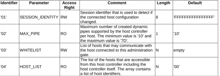
The administration gate in the host controller provides access to services that manage the network of pipes in the HCI network. In addition, this gate provides access to services that allow the discovery of hosts at the first startup and when the configuration of the host network has changed (see clause 8). The registry shall be persistent.
Table 20 lists the entries in the gate registry.
Table 20
Identifier Parameter Access Right
Comment Length Default
'01' SESSION_IDENTITY RW
Session identifier that is used to detect if the connected host configuration changed.
8 'FFFFFFFFFFFFFFFF'
'02' MAX_PIPE RO
Maximum number of created dynamic pipes supported by the host controller per host. The minimum value is '10' and the maximum value is '7D'.
1 '10'
'03' WHITELIST RW
List of hosts that may communicate with the host connected to this administration gate.
N empty
'04' HOST_LIST RO
The list of the hosts that are accessible from this host controller including the host controller itself. The array contains a list of host identifiers.
N '00'
The session identity shall be modified by the host whenever a modification of the configuration is performed by the host. The default value of the session identity shall never be written by a host. The session identity shall use random values.
Every host writes its WHITELIST into the host controller administration gate in order to inform the host controller which hosts are allowed to communicate with it. The host controller shall reject create pipe requests if the source host is not listed in the WHITELIST of the destination host.
The WHITELIST shall not contain the host controller identifier and host identifier accessing the WHITELIST. The WHITELIST is an array containing a list of host identifiers as defined in table 1.
7.1.1.2
Host administration gate
The administration gate at a host provides access to services involved in the management of the pipes towards that host. The administration gate at a host has no registry entries defined.
7.1.2 Link
management
gate
7.1.2.1
Host controller link management gate
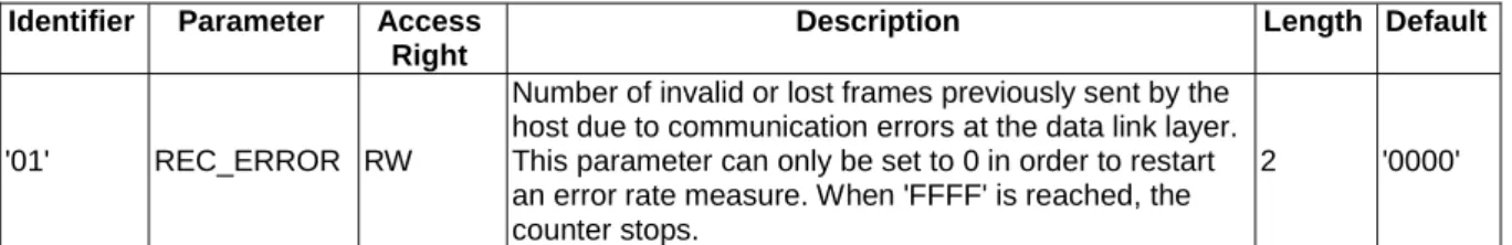
The host controller link management gate provides information about the underlying layer. The registry may not be persistent.
Table 21 lists the entries in the registry.
Table 21
Identifier Parameter Access Right
Description Length Default
'01' REC_ERROR RW
Number of invalid or lost frames previously sent by the host due to communication errors at the data link layer. This parameter can only be set to 0 in order to restart an error rate measure. When 'FFFF' is reached, the counter stops.
2 '0000'
7.1.2.2
Host link management gate
The host link management gate provides access to information related to the link layer. The registry may not be persistent.
Table 22 lists the entries in the registry.
Table 22
Identifier Parameter Access Right
Description Length Default
'01' REC_ERROR RW
Number of invalid or lost frames previously sent by the host due to communication errors at the data link layer. This parameter can only be set to 0 in order to restart an error rate measure. When 'FFFF' is reached, the counter stops.
7.1.3
Identity management gate
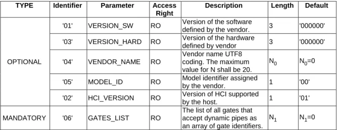
The identity management gate provides software and hardware information about the host. The registry shall be persistent.
This gate shall be provided by all hosts and the host controller. Table 23 lists the entries in the registry.
Table 23
TYPE Identifier Parameter Access Right
Description Length Default
OPTIONAL
'01' VERSION_SW RO Version of the software
defined by the vendor. 3 '000000' '03' VERSION_HARD RO Version of the hardware
defined by vendor 3 '000000'
'04' VENDOR_NAME RO
Vendor name UTF8 coding. The maximum value for N shall be 20.
N0 N0=0
'05' MODEL_ID RO Model identifier assigned
by the vendor. 1 '00'
'02' HCI_VERSION RO Version of HCI supported
by the host. 1 '01'
MANDATORY '06' GATES_LIST RO
The list of all gates that accept dynamic pipes as an array of gate identifiers.
N1 N1=0
A host according to the present document shall set the HCI_VERSION parameter if provided to '01'. The
HCI_VERSION parameter will be incremented for each release of this HCI specification that is not fully backward compatible with the previous release. Every host shall manage backward compatibility with previous HCI versions and use only commands and parameters defined in the present document n having the lower HCI version number exposed by the 2 hosts involved in a transaction. A host connected to a host with higher HCI version number shall operate according to its own version.
7.1.4
Loop back gate
The loop back gate provides access to services for testing the HCI network. The loop back gate has no registry entries defined.
7.2
Generic gates
Generic gates are not related to the management of the host network, but provide functions in the context of their host. For the contactless platform the functions and registries are defined in clauses 9 and 10.
8 HCI
procedures
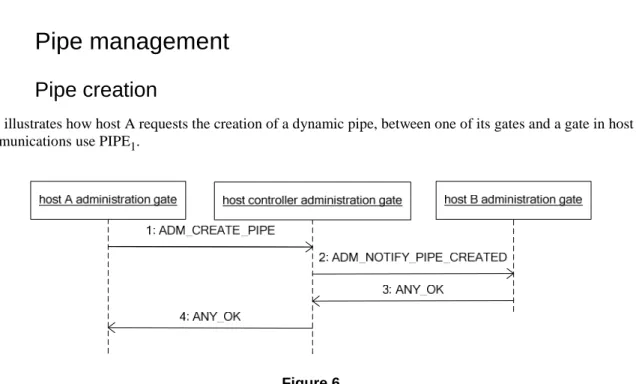
8.1 Pipe
management
8.1.1 Pipe
creation
Figure 6 illustrates how host A requests the creation of a dynamic pipe, between one of its gates and a gate in host B. All communications use PIPE1.
Figure 6 The sequence flow is as follows:
1) Host A requests the host controller to create a pipe, PIPEx. The host controller shall verify that Host B administration gate WHITELIST contains Host A identifier. If Host A is not part of the WHITELIST of Host B, the host controller shall send ANY_E_PIPE_ACCESS_DENIED response to Host A and stop any further processing of this command.
2) The host controller assigns an unused pipe identifier.
3) The host controller notifies host B that host A requested the creation of PIPEx. 4) Host B responds to confirm that it accepts PIPEx.
5) The host controller responds that PIPEx has been created.
6) If host B does not accept the creation of the pipe, it shall respond with an appropriate response code. When the host controller wants to create a pipe then the pipe identifier is assigned and only steps 2 and 3 are needed. When a pipe is created towards the host controller then only steps 1 and 4 are needed.
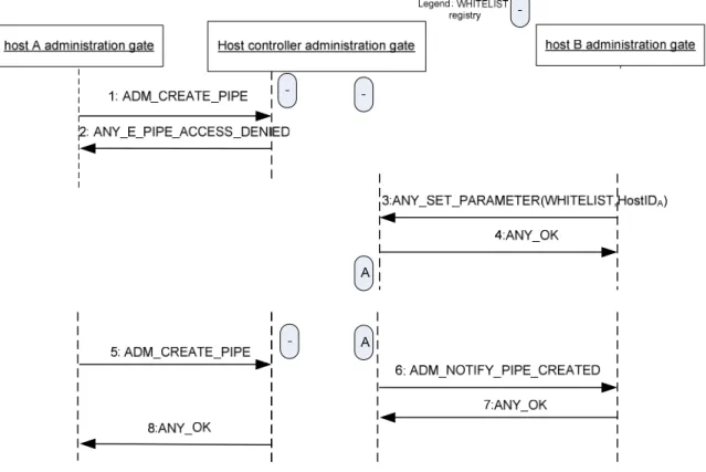
Figure 7 illustrates how the WHITELIST affects a request from a host to create a pipe. In the following, the WHITELIST associated with Host B does not initially contain the HID for Host A and so the request is rejected.
Following updating of the WHITELIST by Host B a further request is accepted.
Figure 7 The sequence flow is as follows:
1) Host A requests the host controller to create a pipe, PIPEx. The WHITELIST in the host controller
administration gate connected to the Host B administration gate does not contain the host identifier of the host A. The Host A is not authorized by Host B.
2) The host controller shall send ANY_E_PIPE_ACCESS_DENIED response to Host A and stop any further processing of this command.
3) The Host B updates its WHITELIST register in the host controller administration gate by adding the Host A identifier.
4) The host controller returns ANY_OK.
5) Host A requests the host controller to create a pipe. The host controller assigns an available pipe identifier. 6) The host controller notifies host B that host A requested the creation of PIPEx.
7) Host B responds to confirm that it accepts PIPEx. 8) The host controller responds that PIPEx has been created.
8.1.2 Pipe
deletion
Figure 8 illustrates how host A requests the deletion of a dynamic pipe, PIPEx, between one of its gates and a gate in host B. All communications use PIPE1.
Figure 8 The sequence flow is as follows:
1) Host A requests the host controller to delete PIPEx. 2) The host controller notifies host B.
3) Host B confirms that it deleted PIPEx.
4) The host controller confirms to host A that the PIPEx is deleted. Pipe deletion cannot be refused by host B.
A pipe created by host A can also be deleted by host B. When PIPEx connects to a gate at the host controller then:
• the connecting host may request the deletion and only steps 1 and 4 are needed; or • the host controller may request the deletion and only steps 2 and 3 are needed.
8.1.3
Clear all Pipes
Figure 9 illustrates how host A requests the host controller to delete all of its dynamic pipes and close all of its static pipes. All communications use PIPE1.
Figure 9 The sequence flow is as follows:
1) Host A requests the host controller to clear all pipes that connect to host A. 2) The host controller signals host B that all pipes are cleared towards host A. 3) Host B confirms.
4) The host controller signals host C that all pipes are cleared towards host A. 5) Host C confirms.
6) The host controller confirms to host A that pipes are cleared and host A closes its static pipes.
8.2 Registry
access
Figure 10 shows how host A can read/write parameters in the registry of host B.
host A
any gate
any gate
host B
1: ANY_GET_PARAMETER
3: ANY_SET_PARAMETER
2: ANY_OK
4: ANY_OK
The sequence flow is as follows:
1) Host A requests a registry parameter from a gate of host B.
2) Host B replies with ANY_OK that includes the parameter value in its data. 3) Host A updates a registry parameter in a gate of host B.
4) Host B confirms that the parameter has been updated.
8.3
Host and Gate discovery
Figure 11 illustrates how a host may discover the hosts in a host network and the gates that a host supports.
1: ANY_GET_PARAMETER(HOSTS_LIST) 2: ANY_OK
host B Identity gate host A
administration gate administration gatehost controller
3: ADM_CREATE_PIPE 5: ANY_OPEN_PIPE 4: ANY_OK 6: ANY_OK host A anyGate 7: ANY_GET_PARAMETER(GATES_LIST) 8: ANY_OK 9: ANY_GET_PARAMETER(VENDOR_NAME) 10: ANY_OK Figure 11 The sequence flow is as follows:
1) Host A uses the administration gate, over PIPE1, to request the list of connected hosts. 2) The host controller returns the list.
3) Host A selects a host from the list, i.e. host B, and requests the host controller, over PIPE1, to create a pipe towards the identity gate of host B.
4) The host controller confirms the creation of the pipe, PIPEx. Details of the pipe creation are shown in clause 8.1.1.
5) Host A opens the PIPEx.
7) Host A requests the list of gates of host B. 8) The list of gates is returned.
9) Host A may request the VENDOR_NAME parameter from the registry. 10) The VENDOR_NAME parameter is returned.
Steps 9 and 10 are optional.
Optionally host A may close and delete PIPEx.
8.4 Session
initialization
As pipe states are persistent, moving the host (e.g. UICC host) into a different terminal may result in inconsistent configurations. Using the session initialization procedure allows a host to detect that the host network has changed, either because the host controller itself changed or because the configuration has been changed. The host shall perform this procedure only at startup and only if no contactless transaction is pending. In case of an underlying data link layer according to TS 102 613 [2] this procedure shall only be performed after the initial interface activation in full-power mode and only if no contactless transaction is pending.
Figure 12 illustrates how a host A detects that the host controller has changed and the subsequent recovery mechanism.
host A
administration gate
administration gate
host controller
1: ANY_GET_PARAMETER(SESSION_IDENTITY)
ANY_OK
initialisation
5: ANY_SET_PARAMETER(SESSION_IDENTITY,ID)
6: ANY_OK
3: ADM_CLEAR_ALL_PIPE
4: ANY_OK
Figure 12The flow is as follows:
1) Host A queries over PIPE1 the SESSION_IDENTITY parameter in the administration gate of the host controller (an ANY_OPEN_PIPE command may precede this command).
2) If the returned value equals the previous value stored in the host then the procedure stops.
3) Otherwise host A needs to reinitialize and it requests the host controller to clear all pipes (see clause 8.1.3). 4) The host controller confirms and host A can perform any initializations.
6) The host controller confirms.
If the host controller stores a configuration (registry values and pipe states) of host A that is used before HCI initialization and need to be protected, an appropriate identity check mechanism shall be implemented by the lower layers. This identity check mechanism is out of the scope of the present document. In case the lower layer identity check fails, the host controller shall:
• execute only the following commands: ANY_OPEN_PIPE, ADM_CLEAR_ALL_PIPE,
ANY_GET_PARAMETER, and only if these are sent on PIPE1. All the other commands shall return
ANY_E_INHIBITED and all events sent to the host controller shall be ignored; and
• return the default value of the SESSION_IDENTITY (see table 20). However the value of the SESSION_IDENTITY in the registry remains unchanged.
This inhibited state shall be terminated after processing a valid ADM_CLEAR_ALL_PIPE command. Additional behaviour of the host controller in case of card emulation is defined in clause 9.4.6.
NOTE: It is up to host controller implementation to maintain the inhibited state after a subsequent successful identity check at the lower layer or not.
8.5
Loop back testing
Figure 13 shows how host A can verify the pipe connectivity to host B.
Figure 13 The sequence flow is as follows:
1) Host A requests over PIPE1 the creation of a pipe between any gate and the loop back gate in host B. 2) The host controller confirms the creation of the pipe, PIPEx. Details of the pipe creation are shown in
clause 8.1.1.
4) Host B accepts the opening.
5) Host A sends the event EVT_POST_DATA with some data as parameter. The loopback gate shall support messages with a size of up to 250 bytes and may also support longer messages.
6) Host B sends back the event EVT_POST_DATA with the same data as received in the previous step. Upon reception host A may compare the received data against the original data.
Optionally host A may close and delete PIPEx.
9
Contactless card emulation
9.1 Overview
This clause specifies how a contactless card supporting multiple RF technologies is emulated on top of HCI core described in the previous clauses.
The RF technologies that are supported are:
• type A as defined in ISO/IEC 14443 parts 2 [5], 3 [6] and 4 [7]; or • type B as defined in ISO/IEC 14443 parts 2 [5], 3 [6] and 4 [7]; or
• type B' compliant with ISO/IEC 14443-2 [5] and with a standard framing as defined in ISO/IEC 14443-3 [6]; • type F as defined in ISO/IEC 18092 [4] as 212 kbps and 424 kbps passive mode.
NOTE 1: Type F technology, framing and protocol is also described in Japanese Industrial Standard
JIS X 6319-4 [i.1]. The JIS terminology is different from ISO/IEC 18092 [4] but the technology is the same.
The contactless platform for card emulation mode is realized as a host network with two hosts; the host controller and the host (e.g. the UICC host). The CLF shall run the host controller of the host network. Additional hosts using the services of the CLF are out of the scope of the present document.
The host operates contactless card applications and the CLF handles the RF communication layers to the external contactless reader.
The host controller has one card RF gate for each RF technology it supports. For each card RF gate it wants to use, the host has one card application gate.
For the contactless platform for card emulation mode the pipes to card RF gates shall be created, opened, closed and deleted by the host. The RF technology of a card RF gate is active when there is an open pipe connected to it. The host shall not create more than one pipe to each RF gate.
For ISO/IEC 14443-4 [7] compliant contactless card applications the processing of the transmission protocol (i.e. up to the layer specified in ISO/IEC 14443-4 [7]) is done in the CLF. The card application gate and card RF gate exchange APDUs over their pipe.
For type B' contactless card applications, the host controller and the host exchange raw frames. The raw frame structure is as defined in ISO/IEC 14443-3 [6]; but the data are transferred without the CRC_B.
In case of an underlying data link layer according to TS 102 613 [2] and for type A contactless card applications that indicate "not compliant with ISO/IEC 14443-4 [7]" in the SAK according to ISO/IEC 14443-3 [6], the CLF and the UICC exchange data using the CLT as defined in TS 102 613 [2].
For Type F contactless card applications, the host controller and the host exchange ISO/IEC 18092 [4]
212 kbps/424 kbps frames. The frame structure is as defined in ISO/IEC 18092 [4] but the data are transferred without PA and SYNC fields and E2.
The host controller activates one or more RF technologies as requested by the host to the external reader. Further details of this activation process are out of scope for the present document.
NOTE 2: Application selection of a contactless card application (using e.g. AID) is out of scope for the present document.
Figure 14 illustrates a valid contactless platform.
Host
type B
application
selection
card application gateHost controller
RF technology
(type A)
card RF gateRF technology
(type B)
card RF gatebanking card
application
type A
application
selection
card application gateloyalty card
application
application
transport
card
non standard
application(*)
CLT
CLT
type B’
application
selection
card application gateRF technology
(type B’)
card RF gatetransport
card
application
type F
application
selection
card application gateRF technology
(type F)
card RF gatetransport
card
application
NOTE: Non-standard applications refer to type A contactless card applications that indicate "not compliant with ISO/IEC 14443-4 [7]" in the SAK according to ISO/IEC 14443-3 [6].
9.2 Void
9.3 Gates
9.3.1 Void
Table 24: Void
9.3.2
Identity management gate
The following parameter shall be added to the identity management gate of the host controller as defined in clause 7.1.3.
Table 25
Identifier Parameter Access Right
Description Length Default
'07' LOW_POWER_SUPPORT RO
Indicates the power mode that is supported; where '01' indicates that low power mode is supported and '00' that it is not supported.
1 N/A
9.3.3
Card RF gates
9.3.3.1 Overview
Card RF gates are located in the host controller. A card RF gate controls the behaviour of a RF technology. Protocol and parameter settings related to the RF technology are available in the RF gate's registry.
The following clauses define the commands and events that a card RF gate supports in addition to those of a generic gate as defined in clause 7.2.
Table 26 lists the GID for the defined card RF gates.
Table 26
Gate GID
Type B card RF gate '21' Type B' card RF gate '22' Type A card RF gate '23' Type F card RF gate '24' Reserved for proprietary use '25' to '29'
9.3.3.2 Commands
There are no additional commands defined.9.3.3.3 Events
The card RF gates supports the event listed in table 27. The events are described in the following clauses. Table 27
Value Event
9.3.3.3.1 EVT_SEND_DATA
This event allows the sending of data to the CLF. The event has parameters as follows:
Table 28
Description Length
data that are sent N
9.3.3.4 Registry
All registries shall be persistent.9.3.3.4.1
RF technology type A
Table 29 defines the registry entries for a card RF gate for RF technology type A. Table 29
Identifier Parameter Access Right
Comment Length Default
'01' MODE RW Type A card emulation enabled indicator 1 'FF'
'02' UID_REG WO UID as defined in ISO/IEC14443-3 [6] for type A N0=0, 4,
7, 10 N0=0 '03' SAK RW Preformatted SAK as defined in ISO/IEC 14443-3 [6] for
type A 1 '00'
'04' ATQA RW
Preformatted ATQA; byte 1 shall contain b8..1, byte 2 b16..9 of the ATQA coded as defined in
ISO/IEC 14443-3 [6] for type A
2 '0000'
'05' APPLICATION_DATA RW The historical bytes as defined in ISO/IEC 14443-4 [7]
for type A N1 N1=0
'06' FWI, SFGI RW Frame waiting time and Start-up frame guard time as
defined in ISO/IEC 14443-4 [7] for type A 1 'EE' '07' CID_SUPPORT RW support for CID as defined ISO/IEC 14443-4 [7] 1 '00'
'08' CLT_SUPPORT RO Support of tunnelling mode for ISO/IEC 14443-4 [7] non
compliant protocols 1 '00'
'09' DATARATE_MAX RW Maximum data rate supported 3 '030300'
Coding for the MODE is as follows:
• 'FF' = Type A card emulation not enabled; and • '02' = Type A card emulation enabled; and • All other values are RFU.
Coding for UID_REG is as follows:
• If Length equals 0 then the CLF shall generate a single size UID with uid0 = '08' and uid1 to uid3 as random number. The random number shall be generated only on state transitions from POWER-OFF to IDLE state (state definitions according to ISO/IEC 14443-3 [6]). The CLF shall interpret the absence of an RF-field as POWER-OFF state.
• If Length equals 4, 7 or 10 then the CLF shall use UID_REG as UID. Coding for the CID_SUPPORT parameter:
• '01' = the support of the CID is required; the CLF shall set CID support in the ATS; and
• All other values are RFU.
Coding for the CLT_SUPPORT parameter:
• '01' = the CLF contains a tunnelling mode capability for type A ISO/IEC 14443-4 [7] non compliant protocol support; and
• '00' = the CLF does not contain any tunnelling mode capability for type A ISO/IEC 14443-4 [7] non compliant protocol support.
DATARATE_MAX codes the maximum divisor supported, with the coding as follows: • Byte 1 defines the maximum divisor supported in direction PCD to PICC:
- '00' = the maximum divisor supported is 1 (~106 kbit/s); - '01' = the maximum divisor supported is 2 (~212 kbit/s); - '02' = the maximum divisor supported is 4 (~424 kbit/s); - '03' = the maximum divisor supported is 8 (~848 kbit/s); - All other values are RFU.
• Byte 2 defines the maximum divisor supported in direction PICC to PCD: - '00' = the maximum divisor supported is 1 (~106 kbit/s);
- '01' = the maximum divisor supported is 2 (~212 kbit/s); - '02' = the maximum divisor supported is 4 (~424 kbit/s); - '03' = the maximum divisor supported is 8 (~848 kbit/s); - All other values are RFU.
• Byte 3 defines a limitation to support different divisors for each direction:
- '00' = different divisors for each directions (PICC to PCD and PCD to PICC) is supported; - '01' = only the same divisor in both direction (PICC to PCD and PCD to PICC) is supported; - All other values are RFU.
NOTE: The resulting actual maximum supported divisor indicated by the interface byte TA(1) as defined in ISO/IEC 14443-4 [7] is given by the minimum of:
the value and limitation as indicated in this registry; and the maximum divisor implemented in the CLF.
9.3.3.4.2
RF technology type B
Table 30 defines the registry entries for a RF gate for RF technology type B. Table 30
Identifier Parameter Access Right
Comment Length Default
'01' MODE RW Type B card emulation enabled
indicator 1 'FF'
'02' PUPI_REG WO PUPI as defined in
ISO/IEC 14443-3 [6] for type B. N0 N0=0 '03' AFI RW Application family identifier as defined
in ISO/IEC 14443-3 [6] for type B 1 '00'
'04' ATQB RW
Additional data for ATQB
4
See Table 31 '05' HIGHER_LAYER_RESPONSE RW
Higher Layer response in answer to ATTRIB command as defined in ISO/IEC 14443-3 [6] for type B
N2 N2=0
'06' DATARATE_MAX RW Maximum data rate supported 3 '030300'
Coding for the MODE parameter:
• 'FF' = Type B card emulation not enabled; and • '02' = Type B card emulation enabled; and • All other values are RFU.
Coding for the PUPI_REG is as follows:
• In case N=0 then the CLF shall generate the PUPI as dynamically generated number. The PUPI shall only be generated by a state transition from the POWER-OFF to the IDLE state (state definitions according to ISO/IEC 14443-3 [6]). The CLF shall interpret the absence of an RF-field as POWER-OFF state. • In all other cases, the CLF shall use the PUPI _REG as PUPI.
Structure of the ATQB parameter.
Table 31
Parameter Comment Length Default
CRC_AID Compressed CRC AID as described in the ISO/IEC 14443-3 [6] 2 '0000' NUMBER_APLI Number of applications as described in the ISO/IEC 14443-3 [6] 1 '00' PROTO_INFO Third byte of the Protocol information as described in the ISO/IEC 14443-3 [6] 1 'E4'
NOTE: PROTO_INFO also encodes FWI and support for CID, which are separate registry parameters in case of Type A.
DATARATE_MAX codes the maximum bit rates supported, with the coding as follows: • Byte 1 defines the maximum bit rate supported in direction PCD to PICC:
- '00' = the maximum bit rate supported is fc/128 (~106 kbps); - '01' = the maximum bit rate supported is fc/64 (~212 kbps); - '02' = the maximum bit rate supported is fc/32 (~424 kbps); - '03' = the maximum bit rate supported is fc/16 (~848 kbps); - All other values are RFU.
• Byte 2 defines the maximum bit rate supported in direction PICC to PCD: - '00' = the maximum bit rate supported is fc/128 (~106 kbps); - '01' = the maximum bit rate supported is fc/64 (~212 kbps); - '02' = the maximum bit rate supported is fc/32 (~424 kbps); - '03' = the maximum bit rate supported is fc/16 (~848 kbps); - All other values are RFU.
• Byte 3 represents the limitation of having the bit rate in both direction compulsory:
- '00' = different bit rates in both directions (PICC to PCD and PCD to PICC) are supported; - '01' = only the same bit rate in both directions (PICC to PCD and PCD to PICC) is supported; - All other values are RFU.
NOTE: The resulting actual maximum bit rate supported is indicated in the first byte of the protocol information as defined in ISO/IEC 14443-3 [6] is given by the minimum of:
the value and limitation as indicated in this registry; and the maximum divisor implemented in the CLF.
9.3.3.4.3
RF technology type B'
Table 32 defines the registry entries for a RF gate for the RF technology type 'B'. Table 32
Identifier Parameter Access Right
Comment Length Default
'01' MODE RW Type B' card emulation enabled indicator 1 'FF' '02' PAT_IN RW Pattern to match with the incoming data N0 N0=0 '03' DAT_OUT RW Data to reply if the incoming data matches with PAT_IN pattern N1 N1=0
Coding for the MODE parameter:
• 'FF' = Type B' card emulation not enabled; and • '02' = Type B' card emulation enabled; and • All other values are RFU.
9.3.3.4.4
RF technology Type F (ISO/IEC 18092 212 kbps/424 kbps card emulation only)
Table 33 defines the registry entries for a RF gate for the RF technology Type F. Table 33
Identifier Parameter Access Right
Comment Length Default
'01' MODE RW Type F card emulation enabled indicator 1 'FF' '02' SPEED_CAP RO CLF Speed Capabilities for Type F 1 '01' '03' CLT_SUPPORT RO Support of tunnelling mode for anti-collision data
Coding for the MODE parameter:
• 'FF' = Type F card emulation not enabled; and • '02' = Type F card emulation enabled; and • All other values are RFU.
Table 34 defines the coding for the SPEED_CAP parameter. Table 34
SPEED_CAP Meaning
b8 1: auto bit rate detection supported 0: auto bit rate detection not supported b7..b3 RFU
b2 1: 424 kbps bit rate supported 0: 424 kbps bit rate not supported b1 1: 212 kbps bit rate supported
0: 212 kbps bit rate not supported
Coding for the CLT_SUPPORT parameter:
• '01' = the CLF contains a tunnelling mode capability for type F card emulation anti-collision support; and • '00' = the CLF does not contain any tunnelling mode capability for type F card emulation anti-collision
support.
9.3.4 Card
application
gates
9.3.4.1 Overview
A card application gate controls the access towards contactless card applications.
The next clauses define the commands and events that a card application gate supports in addition to those of a generic gate as defined in clause 7.2.
The GID for the card application gates are dynamically assigned by the host.
9.3.4.2 Commands
No additional command defined.9.3.4.3 Events
The card application gates support the events listed in table 35. The events shall be described in the following clauses. Table 35 Value Event '10' EVT_SEND_DATA '11' EVT_FIELD_ON '12' EVT_CARD_DEACTIVATED '13' EVT_CARD_ACTIVATED '14' EVT_FIELD_OFF
9.3.4.3.1 EVT_FIELD_ON
This event signals that the CLF detected an RF carrier from an external reader. This event shall be sent by the host controller within 2ms after the detection of an RF field.
In case of an underlying data link layer according to TS 102 613 [2], the following exception applies: if SWP is in DEACTIVATED state, the CLF shall activate the interface instead of sending the EVT_FIELD_ON.
The event has no parameters.
9.3.4.3.2 EVT_CARD_DEACTIVATED
This event signals that the CLF is deactivated as defined in ISO/IEC 14443-3 [6] for type B or ISO/IEC 14443-4 [7] for type A.
The event has no parameters.
9.3.4.3.3 EVT_CARD_ACTIVATED
This event signals that the CLF is activated as defined in ISO/IEC 14443-3 [6] for type B or ISO/IEC 14443-4 [7] for type A.
The event has no parameters.
9.3.4.3.4 EVT_FIELD_OFF
This event signals that the CLF detected the loss of the RF carrier from the external reader. The event has no parameters.
9.3.4.3.5 EVT_SEND_DATA
This event allows the sending of data to the host from the CLF. The event has parameters as follows: Table 36
Description Length
data that are sent N RF error indicator 1
Coding for the RF error indicator: • '00' = no error; and • '01' = error; and
• All other values are RFU.
NOTE: The end of the data and the beginning of the RF error indicator can unambiguously be derived from the message size. The RF error indicator is the last parameter, as the first segments of a long segmented message may already have been sent on the interface to the host before the sender (CLF) can do the integrity check of the original message received on the contactless interface.
The event shall be discarded by the host when the error indicator is set to '01'.