Original Article
Technology Selection for Offshore Underwater
Small Modular Reactors
Koroush Shirvan
*, Ronald Ballinger, Jacopo Buongiorno, Charles Forsberg,
Mujid Kazimi
1, and Neil Todreas
Department of Nuclear Science and Engineering, Massachusetts Institute of Technology, Cambridge, MA, USA
a r t i c l e i n f o
Article history:Received 23 December 2015 Received in revised form 1 June 2016
Accepted 6 June 2016 Available online 16 June 2016
Keywords:
Advanced Reactors Nuclear Design Nuclear Safety Offshore Power Cycle Small Modular Reactor
a b s t r a c t
This work examines the most viable nuclear technology options for future underwater designs that would meet high safety standards as well as good economic potential, for construction in the 2030e2040 timeframe. The top five concepts selected from a survey of
13 nuclear technologies were compared to a small modular pressurized water reactor (PWR) designed with a conventional layout. In order of smallest to largest primary system size where the reactor and all safety systems are contained, the top five designs were: (1) a leadebismuth fast reactor based on the Russian SVBR-100; (2) a novel organic cooled
reactor; (3) an innovative superheated water reactor; (4) a boiling water reactor based on Toshiba's LSBWR; and (5) an integral PWR featuring compact steam generators. A similar study on potential attractive power cycles was also performed. A condensing and recom-pression supercritical CO2cycle and a compact steam Rankine cycle were designed. It was
found that the hull size required by the reactor, safety systems and power cycle can be significantly reduced (50e80%) with the top five designs compared to the conventional
PWR. Based on the qualitative economic consideration, the organic cooled reactor and boiling water reactor designs are expected to be the most cost effective options.
Copyright©2016, Published by Elsevier Korea LLC on behalf of Korean Nuclear Society. This is an open access article under the CC BY-NC-ND license (http://creativecommons.org/ licenses/by-nc-nd/4.0/).
1.
Introduction
With the rise of interest in small modular reactors (SMRs), DCNS in France is working on a 160-MWe offshore underwater reactor. The DCNS underwater power plant, called Flexblue, resembles a nuclear submarine without the ability to self-propel [1]. Flexblue would be anchored to the seabed compared to a terrestrial reactor. An undersea and
transportable reactor has several advantages. First, the ocean heat sink provides an accessible near-infinite source of water for passive safety cooling of the core in the event of loss of normal reactor system cooling. Second, the underwater offshore siting of the reactor allows installation in areas nor-mally interdicted to large land-based plants, for instance: re-gions near dense populations, with harsh weather and climate, or subject to natural threats such as tsunamis. Third,
*Corresponding author.
E-mail address:[email protected](K. Shirvan).
1Deceased.
Available online at
ScienceDirect
Nuclear Engineering and Technology
journa l home page:www.elsevier.com /locate/ne t
http://dx.doi.org/10.1016/j.net.2016.06.002
1738-5733/Copyright©2016, Published by Elsevier Korea LLC on behalf of Korean Nuclear Society. This is an open access article under the CC BY-NC-ND license (http://creativecommons.org/licenses/by-nc-nd/4.0/).
similar to most land-based SMRs, the reactor is entirely manufactured in a factory or shipyard, which could save construction time and money. It eliminates the massive concrete structures needed on land including the basemat and containment walls. Transportability may allow flexible installation and a new business model for the nuclear in-dustry, where a plant could change owner and location several times in its lifetime[2]. Buongiorno et al.[2]provide a more detailed discussion on the advantages of offshore siting. The major drawback of such a plant is its complicated main-tenance and refueling operation.
The Flexblue design is based on a standard pressurized water reactor (PWR) technology. While PWRs are the domi-nant technology for land-based nuclear power plants, they may not be the optimal choice for the offshore underwater setting. The work reported here is the result of a comparative study of promising designs that may lead to improved per-formance in a future seabed-anchored SMR based on certain goals and constraints. Previous published work[3]focused on narrowing the promising reactor technologies from 13 to five and viable advanced power cycle systems from six to three. The design priorities used to narrow down the 13 technologies for this study were in the following order of decreasing importance:
➢ Safety: Ability to fulfill the safety objectives (reactivity control, decay heat removal and radioactivity contain-ment) by passive means for an indefinitely long period.
➢ Compact reactor layout, to maximize power density of the plant
➢ Achievement of a long fuel cycle to increase plant availability.
➢ High thermodynamic efficiency of the power conversion cycle
➢ High compactness of the power conversion cycle (turbi-neegenerator cycle)
➢ High dual-use resistance: this includes weapons prolifer-ation resistance and unsuitability for military applicprolifer-ations (including propulsion).
➢ Sufficient technology maturity to be deployable by 2030e2040.
The following design constraints were imposed on this study to meet the desired performance goals:
➢ 160 MWe power output
➢ The hull (containment) dimensions are limited to 15 m in diameter due to manufacturing constraints by DCNS and 20 m in vertical height to assure the hull is sufficiently submerged in 30-m-deep water.
➢ The reactor is to be deployable in 30e100 m of water. ➢ The safety systems must be able to operate for an
indefi-nitely long period using passive decay heat removal.
➢ In case of accidents, releases of radioactivity outside the hull must be prevented.
➢ The fuel U235enrichment must remain below 19.75% to mitigate proliferation concerns.
➢ The desired fuel cycle length is>5 years but<9 years due to unavoidable maintenance needs per DCNS recommen-dation. The challenge of maintenance-free extended
operation (>2 years) along with potential solutions for the IRIS SMR design has been investigated in the past[4]. While a 4-year fuel cycle was deemed feasible for the IRIS SMR design, future detailed study on feasibility of a 5e9 year
fuel cycle length for 2030e2040 deployment time frame
needs to be performed.
The initial 13 nuclear technologies were assessed with respect to the various priorities and constraints. A summary of this selection process is listed inTable 1. The achievement of safety and compact reactor design were the two top prior-ities. A limitation on the vertical containment height (20 m) and a minimum fuel cycle length of 5 years were the most restrictive constraints. Among the reactor concepts consid-ered, the sodium fast reactor was eliminated due to in-compatibility of sodium with water, which could occur in case of catastrophic failure of the hull. The gas fast reactors [He and supercritical (S)CO2-cooled designs] were eliminated due to
the difficulty to achieve a fully passive safe design. Four con-cepts (supercritical water, molten salt fuel, salt cooled, and gas-cooled high-temperature thermal reactors) were elimi-nated due to an inability to achieve>5 year refueling intervals while achieving satisfactory economic operation by 2030e2040. The CANDU design was eliminated due to
requiring a larger hull size than the design constraint. The five concepts that remained viable according to the adopted design priorities and constraints were: the PWR; the boiling water reactor (BWR); the superheated water reactor (SWR); the leadebismuth fast reactor (LBFR); and the organic cooled
reactor (OCR). For the BWR, the Toshiba LSBWR and for the LBFR, the Russian SVBR-100 were chosen as reference designs that can be used without further development, while addi-tional investigations were performed for the other three concepts. See Shirvan et al.[3]for more details regarding this selection process.
This work focuses on comparison of the top five chosen technologies with their respective advanced compact power cycles. A brief overview of the five technologies is given with more focus on the integrated PWR, the advanced version of the PWR option, since its design details have not yet been published elsewhere. The comparison to a conventional PWR design is then performed.
2.
Overview of technologies
This section includes an overview of the top five selected de-signs to meet the design criteria.
2.1. Reference PWR design
The current Flexblue reactor is rated at 530 MW thermal power that produces 160 MW electric power by assuming 33% cycle efficiency and 15 MWe losses due to electricity delivery to the land as well as auxiliary system consumption[1]. The core is assumed to operate at a relatively low 69-kW/L power density, similar to the US mPower design [17]to minimize enrichment requirements for the extended target cycle length as well as increased margin for transients but at the cost of a
larger reactor pressure vessel. The Flexblue reactor is accommodated within a 14-m diameter and a 145-m-long horizontal hull. The reactor section is approximately 25e30 m
long, while the turbine and alternator section is approxi-mately 40e50 m long. The other functions taking most of the
remaining space are the emergency power supply system, in the form of batteries, as well as living areas for 15e30 people.
The reactor is a PWR, and power conversion is done through a traditional steam Rankine cycle. Unlike most SMRs, the PWR layout is not an integral configuration, that is, the steam generators and pressurizer are not within the same pressure vessel as the core.
The main advantage of the PWR is that it is a proven technology and has a strong industry infrastructure to support its development. The other advantage is its ability to achieve extended fuel cycle length with a high degree of reliability. However, by operating at very high pressure, the PWR requires thicker pressure boundary sections and careful consideration of rapid loss of coolant inventory accident scenarios. 2.2. Integral PWR
A straightforward approach to increase the economic competitiveness of a PWR for offshore deployment is to reduce the hull (containment) size required to accommodate it. To provide an alternative to the typical PWR design such as Flexblue, the integral configuration is chosen due to its po-tential to be able to reduce containment size and eliminate large break loss of coolant accidents by design. Recently, integral-type PWRs such as B&W's mPower and Nuscale de-signs have gained significant attention. The integral configu-ration contains the core, steam generators, pressurizer and possibly pumps and control rod drives (CRDs) within the reactor vessel. The mPower design places the pumps outside of the vessel while the CRDs are inside the vessel. The main advantages of putting CRDs inside are to avoid control rod ejection accidents, and to avoid penetrations through the upper vessel head. However, in some designs, such as the Korean SMART reactor, the CRDs have remained outside of
the vessel[9]. The thought process in the Korean case for their design choice was that sufficient margin exists to sustain the rod ejection accidents with external CRDs and, at the same time, keeping CRDs external avoids additional licensing cost.
2.2.1. Compact heat exchangers
The primary disadvantage of the integral type configuration is its requirement for a larger vessel size. In order to take advantage of benefits of an integral configuration and meet the 20 m vertical constraint on the height of the hull, the use of compact heat exchangers is necessary. The use of compact heat exchangers to reduce the size of the vessel of an integral PWR has been proposed by Shirvan et al. [18]and later on adopted by the Westinghouse SMR [19](compact shell-and-tube heat exchangers) and the I2S-light water reactor (LWR) integral reactor designs (printed circuit heat exchangers: PCHEs) [20]. The PCHE is a type of proven compact heat exchanger that provides for high power density along with low-pressure drop and reduced maintenance requirements for its current application in chemical processing plants. The PCHEs are made of a stack of metallic plates with semicircular passages that are diffusion bonded on top of each other[21], as shown inFig. 1A. The diffusion bonds have the same strength as the parent material, which could be made out of stainless steel of a nickel-based alloy for high temperature applications. Thus, the likelihood of accidents induced by the pressure differential between the primary and secondary system, such as the steam generator tube rupture, is reduced for the PCHE design. The PCHE has been proposed for advanced reactors as well as the SCO2power cycle and has been investigated for
nuclear applications by many organizations including Argonne National Laboratory, Georgia institute of Technology, Idaho National Laboratory, KAERI, MIT, Sandia National Lab-oratory, Tokyo Institute of Technology, and Westinghouse
[22].
Helical steam generators have also been proposed for in-tegral reactor designs such as NuScale as well as the IRIS design. The PCHEs have shown the potential to be designed with surface area density of 1,420 m2/m3and power density of
Table 1eOverview of the design selection process.
Reactors Base design Key merit Key deficiency
PWR Flexblue[1] Existing proven technology Low thermodynamic efficiency BWR LSBWR[5] Existing proven technology Low thermodynamic efficiency SWR MIT[6] High thermodynamic efficiency Requires materials R&D
LBFR SVBR-100[7] Very compact O&M cost to prevent solidification of leadebismuth eutectic
OCR MIT[8] Compact No global support for its R&D
CANDUa CANDU-6[9] Existing proven technology Too large SCWRa INL[10] High thermodynamic efficiency Poor thermal
ehydraulic stability MSRa Fuji[11] High thermodynamic efficiency Hot maintenance of all components FHRa MIT/UCB[12] High thermodynamic efficiency Materials R&D
SFRa ANL[13] Compact Reaction with water
HTGRa GTHRT-300[14] High thermodynamic efficiency Large
GFRa CEA[15] High thermodynamic efficiency Not fully passive SCO2GFRa MIT[16] High thermodynamic efficiency Not fully passive a These designs were eliminated.
BWR, boiling water reactor; FHR, fluoride high temperature reactor; GFR, gas fast reactor; HTGR, high temperature gas reactor; LBFR, leadebismuth fast reactor; MSR, molten salt reactor; OCR, organic cooled reactor; O&M, operations and management; PWR, pressurized water reactor; R&D, research and development; SCO2, supercritical CO2; SCWR, supercritical water reactor; SFR, sodium-cooled fast reactor; SMR,
180 MW/m3compared to an equivalent helical steam
gener-ator with surface area density of 173 m2/m3and power density
of 7.5 MW/m3. For a more detailed discussion, see Shirvan et al.[18].
For this study, where the thermal power is 530 MWth, 10 PCHEs with a total length of 60 cm (30 cm to accommodate headers), width of 60 cm, and height of 2 m are required. As shown inFig. 1A, 12 PCHEs of this size can be accommodated in the chosen inner reactor pressure vessel (RPV) diameter of 3.9 m. The extra two PCHEs provide redundancy and increase operational reliability and as well can be utilized in case of excessive fouling or other issues that may degrade PCHE unit performance. Finally, the PCHE cost should be very competi-tive with the shell and tube steam generators, due to the compactness of the PCHEs. Based on ASPEN[23]calculations, a heat exchanger sizing commercial tool, for a single 125-MWth once-through shell and tube steam generator of similar operating conditions, an estimated cost of $2.5 million was determined for a heat exchanger fabricated of Inconel 600. In contrast, according to estimates from Dewson and Grady[24], the cost of a PCHE made of Type 316 stainless steel was estimated to be 132 K$/m3in 2003 dollars or 170 K$/m3in
2014[25]. This would mean a total of only $1.5 million for the base design reactor today, which is approximately 10 times cheaper than a once-through steam generator. For Inconel 600, if chosen for corrosion concerns, the PCHE cost is still expected to be more than twofold cheaper than a once-through steam generator. It is noted that the cost estimates for both types of steam generators were for non-nuclear grade designs.
While there are some experimental data for single-phase water in the channels shown inFig. 1, the performance of the channels for steam generation has yet to be demonstrated by experiment. The long-term corrosion and fouling perfor-mance for prototypical PWR primary and secondary sides are yet to be available in open literature. In the case of excessive corrosion, additional space for full flow demineralizers is likely to be required to reduce such concerns. This is the pri-mary reason why the I2S-LWR reactors only uses compact heat exchangers for a single-phase to single-phase heat exchanger and perform the steam generation in a flashing chamber at a cost of thermal efficiency and additional component[22]. The details of inspection and testing of PCHEs within a nuclear reactor also require further attention.
2.2.2. Reactor and containment design
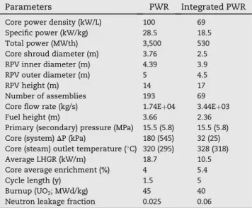
For the reactor core, the standard Westinghouse 1717 as-sembly used in most US SMR designs was selected in this study. The introduction of compact heat exchanger and in-tegral layout of the vessel requires a redesign of the hull and containment.Table 2summarizes the core parameters of the advanced integrated PWR relative to a standard US PWR. The vessel thickness is taken to be approximately the same as the SMART PWR[26]. The steam generators are once-through and therefore superheated steam can be supplied to the turbine, which slightly increases the efficiency. The far lower pressure drop and pumping power required will also afford a small efficiency increase.
Fig. 2A shows the approximate vessel and containment design features. As noted in the figure, the total height of the hull is 20 m with a diameter of 14 m. This is approximately 30% more compact than the equivalent PWR conventional layout. The free volume in the hull is 1,400 m3and modeled
with air at approximately atmospheric pressure and 315K. The internal suppression pool above the vessel has a volume of 635 m3and houses a heat exchanger that acts as a decay heat
Fig. 1e(A) Cross-section of two layers of the printed circuit heat exchanger (PCHE) showing the semicircular coolant paths
[21]. (B) The 1/4 layout of the PCHE in the vessel relative to the core (it is noted that the core is at lower elevation compared to the PCHEs).
Table 2eThe integral pressurized water reactor design
vs. a typical 1,000 MW class pressurized water reactor (PWR).
Parameters PWR Integrated PWR Core power density (kW/L) 100 69
Specific power (kW/kg) 28.5 18.5
Total power (MWth) 3,500 530
Core shroud diameter (m) 3.76 2.5 RPV inner diameter (m) 4.39 3.9
RPV outer diameter (m) 5 4.5
RPV height (m) 14 17
Number of assemblies 193 69
Core flow rate (kg/s) 1.74Eþ04 3.44Eþ03
Fuel height (m) 3.66 2.36
Primary (secondary) pressure (MPa) 15.5 (5.8) 15.5 (5.8) Core (system)DP (kPa) 180 (545) 32 (25) Core (steam) outlet temperature (C) 320 (295) 328 (318)
Average LHGR (kW/m) 18.7 10.5
Core average enrichment (%) 4 5.4
Cycle length (y) 1.5 5
Burnup (UO2; MWd/kg) 45 40
Neutron leakage fraction 0.025 0.06 LHGR, linear heat generation rate; RPV, reactor pressure vessel.
removal system during normal shutdown as well as emer-gency situations. The pressure in the system can be decreased through an automatic depressurization system, taking the steam in the pressurizer to condense in the suppression pool. Outside the vessel, an emergency boron injection tank is sit-uated to flood the core with high concentration of boron, as a
secondary means of shutdown. The integral vessel has a large pressurizer on the top to slow down the response during transients by providing over 4.5 times the volume of liquid water per MWth compared to a typical PWR pressurizer. The integral configuration allows the primary system to be con-tained in a single vessel and eliminates the large-break loss of
coolant accident (LOCA). This allows the containment volume to be more compact as the largest pipe size is the direct vessel injection line for emergency core cooling with a diameter of 50 mm, consistent with the SMART integrated PWR that is licensed in Korea[27]. There are also heat exchangers above the containment vessel to remove heat from the containment top which has a surface area of only ~200 m2. The reason these heat exchangers are separated from the containment is to avoid any containment bypass on top of the hull. This space is actually not needed and the hull can just be extended to this region or shortened based on RELAP5 transient simulations. The hull (containment) is assumed to be fabricated from 5-cm-thick steel [1] providing structural support and margin for overpressure transients.
2.2.3. Safety behavior
The safety behavior of the system was analyzed using RELAP5.
Fig. 2B shows the system configuration schematic for the RELAP5 analysis. For the RELAP5 analysis, two accident sce-narios have been simulated. The first is a total loss of feed-water, where the feedwater flow drops to zero instantly, followed by (2 s later) a SCRAM and pump trip. The second accident is a 50-mm break at a location just above the core where the emergency boron tank is connected. Feedwater is also discontinued, while the reactor core SCRAMs and the pumps trip 2 s following the break.
The only boundary conditions used in these simulations are the feedwater flow rate, turbine inlet pressure and the convection heat removal rate for the hull. The first two boundary conditions are only used to allow the systems shown in Fig. 2B to reach their steady state conditions. Therefore only one fixed boundary condition is assumed throughout the transients. The heat transfer on the hull sur-face is calculated using the ChurchilleChu natural convection
correlation [28]. The standard condensation heat transfer model that accounts for noncondensable gases in RELAP5 is utilized. It is also noted that only the circumference of the hull is used as a heat transfer medium. The top and bottom regions are conservatively assumed to be insulated.
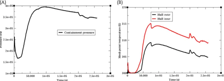
The pressure and temperature of the hull up to 72 h after total loss of feedwater flow are shown in Fig. 3. As seen, considering the hull pressure limit of 9 bar[1], the system is able to safely control the in-hull temperature and pressure using only passive cooling.
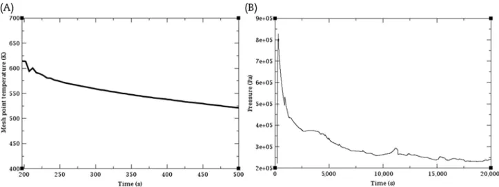
One of the main parameters of interest in a LOCA simula-tion is the peak cladding temperature that typically occurs within the first 100s of seconds upon core blow down and refill during a large-break LOCA for typical PWRs. Since only a small-break LOCA can occur in this design, the core remains covered during the initial rapid depressurization rate and, as shown inFig. 4A, the cladding temperature never exceeds the steady state peak temperature. The peak containment pres-sure, as shown inFig. 4B remains below the 9-bar limit.
2.3. BWR
The development of nuclear technology in the USA was started by the naval nuclear program. In a nuclear subma-rine, since a BWR balance of plant had radioactive water in its circulation and a BWR could undergo flow and power os-cillations induced by ship motion due to operation with two-phase flow and susceptibility to flow instabilities (i.e., density wave oscillations), the navy selected the PWR. This sensi-tivity to motion is actually an advantage of BWRs for un-derwater civilian reactor use, since they could not be readily adapted to dual use for submarine propulsion. The other main advantage of the BWR compared to an integral PWR is lower cost of manufacturing due to elimination of the vol-umes of the steam generators and pressurizer, and possibly thinner RPV by operating at approximately half the pressure of a PWR.
The base design for the BWR SMR technology is taken to be the Toshiba LSBWR [4]. The LSBWR, similar to Hitachi's SSBWR, uses natural circulation for full power operations as well as locating the control rods at the top of the core to avoid any penetrations to the vessel at low elevations. This config-uration along with lower operating pressure, reduces the required safety injection capacity, compared to PWRs. In
Fig. 3e(A) The hull pressure and (B) temperature response during the total loss of feedwater accident for the integrated pressurized water reactor design.
addition, the Hitachi ABWR, through use of modular con-struction, has been shown to have the fastest construction time compared to any rival PWR (approx. 48 months for a 4,000-MWth plant).
The main drawback of the BWR with respect to the PWR is the high-radiation levels in the balance of plant, requiring expensive shielding and more restricted access to many components in the steam cycle. Another disadvantage is its lower power density (approximately half), although it is comparable to the integral PWR SMR design. A third disad-vantage, highlighted in the Fukushima accident, is the higher zirconium loading in the core due to presence of additional zirconium from assembly boxes. The number of BWRs under operation and construction has also been rapidly decreasing in the last few years. However, a new vendor will have the competitive edge of offering the only BWR as an SMR if they decide to pursue such technology.
For the purpose of this study, the containment of the BWR was assumed to be the same as the SWR reactor discussed in the next section, since the overall power rating and water inventory are similar.
2.4. SWR
The concept of an SWR was explored in the 1950s and 1960s, with only few years of operational experience accumulated in the USA and Germany[6]. The main motivation behind the SWR concept is to produce superheated steam at around 500e600C, to increase the thermodynamic efficiency of
LWRs. A 200C increase in steam temperature results in an approximately 4% increase in efficiency with anidealsimple Rankine cycle.
The base design used to represent an SWR is the conceptual design developed by Ko and Kazimi in 2010 (Fig. 5). The reason the earlier concepts or other conceptual SWR designs discussed in the literature were not chosen for the SWR base design is that they all suffered from power/flow mismatch stability issues, since they isolated boiling in one region of the core and
superheating the steam in another region. In the Ko and Kazimi design, this is solved by using internally and externally cooled annular fuel (IXAF). The coolant boils in the external channels throughout the core to approximately the same quality as a conventional BWR and the steam is separated from the liquid with the use of traditional separators. Then this saturated steam, instead of exiting the RPV, turns around and flows downward in the central channel of some IXAF fuel rods within each assembly and then flows upward through the rest of the IXAF pins in the assembly and exits the RPV as superheated steam. The IXAF fuel concept has been extensively studied in the 2000s for both PWRs and BWRs[29]and is currently being irradiated in Korea to assess its application for providing power uprates to the OPR1000 PWR design[30].
A survey of cladding options resulted in two potential cladding materials to withstand the conditions of the SWR for a 5-year refueling cycle: FeCrAl and Type 310 stainless steel
[31]. The two metal claddings do require higher enrichment compared to zircaloy cladding. Type 310 steel and FeCrAl cladding result in average core U235enrichments of 8.8% and
9.4%, respectively. The Type 310 stainless steel, due to its nickel content, requires 0.6% higher U235 enrichment
compared to FeCrAl cladding.
Fig. 5displays the SWR layout along with some selected design specifications. The noted 40% thermal efficiency is calculated by assuming the power cycle technology outlined in Section3and the turbo-machinery isentropic efficiency will improve from approximately 85% to approximately 90% by the 2030 time-frame. If a similar assumption is applied to the in-tegrated PWR in section2.2, the thermodynamic efficiency of approximately 37.5% is calculated. Similar to the advanced integrated PWR design, the hull size has a diameter of 14 m and a height of 20 m with similar elevated internal suppres-sion pool, used for decay heat removal as well as safety functions.
The safety assessment is presented by Shirvan and Kazimi
[32]. The SWR showed unique transient and thermomechan-ical behavior relative to a BWR, but no show stoppers were
Fig. 4e(A) Maximum cladding temperature and (B) containment pressure during the small-break loss of coolant accident for the integrated pressurized water reactor design.
seen with its performance. In addition to the fuel enrichment penalty, the weakness of the SWR performance relative to a BWR was observed in the class of transients where sudden increase in power due to negative void coefficient of reactivity would result in large increases in the steam temperature in the core.
2.5. LBFR
The LBFR offers compatibility with water and air, resulting in a smaller containment requirement while maintaining similar operating pressure and temperatures compared to sodium-cooled fast reactors, but with poorer thermal hydraulic and corrosion performance. The LBFR is a more compact design with higher thermodynamic cycle efficiency compared to PWRs. The leadebismuth eutectic (LBE) also provides a very
large margin to boiling of the coolant. However, the coolant freezing scenarios are equally concerning as the overheating scenarios. Upon neutron activation of the LBE coolant, there are concerns about its radiotoxicity, mostly due to Po-210, in addition to the toxicity of lead. The reference LBFR design used in this study was the Russian SVBR-100[7], which ben-efits from the experience of operating multiple LBFR-based nuclear submarines in Russia over the past decades, making the LBFR concept a viable deployable option for an underwater reactor by 2030e2040. The SVBR-100 is rated at a similar power
density and thermodynamic cycle efficiency as a PWR, which is lower than other typical LBFR conceptual designs described in the literature. The more conservative operating conditions of the LBFR are based on the Russian experience with mate-rials under irradiation and flow of LBE. While tremendous
progress has been made in material selection for LBFR con-cepts[33]long-term corrosion of in-core materials is still a concern. Finally, it should be noted that the SVBR-100 deployment has not shown progress in recent years.
2.6. OCR
The OCR concept was originally investigated in the late 1950s as an organically cooled (Santowax) and moderated design. This design was abandoned by the early 1970s, with the closure of the Canadian heavy water moderated OCR at the Whiteshell laboratories. The main disadvantage of organic reactors is the disassociation of the coolant under high tem-perature and radiation fields. Therefore, the Canadian reactor made use of hydrocracker technology, which is commonly used today in the oil and gas industry, to recover and recycle the dissociated coolant and maintain an equilibrium coolant composition[34]. For an underwater concept, the disadvan-tage is the additional space required for storage of replace-ment organic coolant, as well as the hydro cracking system.
The Canadian OCR design also used a heavy water moderator to reduce the radiation energy deposition on the organic coolant. The use of solid moderator was investigated in this study instead of heavy water. Graphite is the earliest used solid moderator for nuclear applications. However, the use of graphite typically results in very large systems with low power density, similar to the heavy water moderated design. The other common solid moderator used in nuclear reactors is zirconium hydride, which allows for designing more compact systems compared to graphite. The use of ZrHXis best known
in TRIGA research reactors [35]. ZrHx has temperature
limitations to lower hydrogen diffusion as well as maintain its structural integrity. The hydrogen concentration of 1.6 is picked (e.g. ZrH1.6) as recommended by Macdonald et al.[36].
Since the organic coolant outlet temperature is around 350C, it is expected that the hydrogen concentration will not decrease significantly over 5 years of operation before refueling.
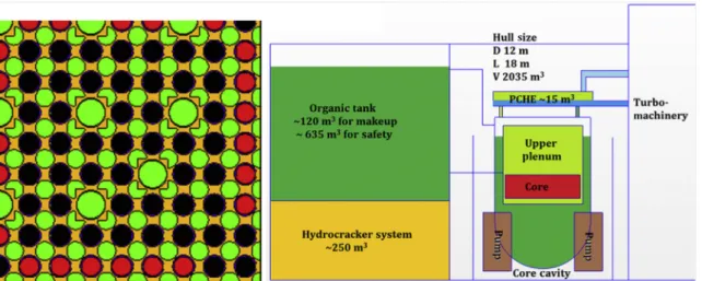
Fig. 6A illustrates a fuel assembly design with graphite and ZrH1.6designed such that the void feedback is negative (see
Macdonald et al.[36]for calculation details). The assembly dimensions are similar to the integrated PWR assembly design. The graphite makes up 40% of the coolant volume and the coolant flows in 7.6 mm circular hole. The assembly con-sists of 66 ZrH1.6 rods and 198 uranium carbide fuel rods.
Uranium carbide with theoretical fuel density of 13.6 g/cm3is
able to offset the loss of fuel mass due to reduction in number of fuel rods compared to a PWR, to maintain similar enrich-ment limits[37]. Other fuel forms such as UO2, UN, or metal
fuel can also be used, since the organic fluids in general are compatible with almost all materials. The assembly design in
Fig. 6A also features acceptable levels of energy deposition by neutrons and gammas in the coolant. A possible plant layout is shown inFig. 6B. The new organic concept has a higher power density (40 kW/L) compared to the Canadian design (15 kW/L), as well as requiring no space for heavy water sys-tems. Therefore, the volume required for this system with updated volumes calculated for hydrocracker and makeup for organic for period of 5 years was used to create a new plant layout design[36].Fig. 6B shows such a layout using compact heat exchangers for a 500 MWth plant, similar to the reference PWR design power output. Similar to the integrated PWR design, the use of compact heat exchangers results in a large saving of space. The volume required to accommodate the organic tank and hydrocracker system is also shown inFig. 6B. While the boiling point of the organic fluid is much higher (~350C) than water at atmospheric pressure, its thermal ca-pacity is approximately half that of water. Hence the volume of organic fluid needed for safety injection from the suppres-sion pool is assumed similar to the PWR.
The safety assessment of such a design and its further de-tails of core-wide design and safety systems are left as future
work. It is important to note that the combination of operation at low pressure (20 times less than the PWR) and moderate temperatures, minimal induced-radioactivity and cheaply available organic fluids in the oil and gas industry, makes the OCR concept exploration a potentially more cost effective R&D effort compared to other advanced reactor designs.
3.
Power cycle
As outlined by Shirvan and Kazimi [32], three promising power cycles were explored as an alternative to the traditional steam Rankine power cycle:
1. Condensing SCO2power cycle featuring three turbines and
two compressors
2. Recompression SCO2 power cycle featuring one turbine
and two compressors
3. Compact steam Rankine cycle with the same efficiency as the traditional steam Rankine cycle but featuring a high-speed turbine generator along with low-pressure and high-pressure turbines and an out-of-hull condenser where DC-to-AC conversion will occur on-shore.
Regarding power cycle efficiency, as listed inTable 3, for the BWR and PWR, either steam Rankine power cycle results in 2% and 10% (absolute) higher thermodynamic efficiency compared to the condensing and re-compression SCO2power
cycle options, respectively. The steam Rankine power cycle efficiency is increased by 2.5% when the inlet turbine tem-perature is increased from approximately 300C to approxi-mately 500C (applicable to SWR and LBFR technologies). At a turbine inlet temperature of approximately 500C, the condensing SCO2power cycle results in 7% higher efficiency
than either steam Rankine cycle while the re-compression SCO2 power cycle results in similar efficiency as either
steam Rankine cycle. It is noted that the condensing SCO2
power cycle is only viable at seawater temperatures below 15C, which may limit the number of suitable sites[38]. As listed inTable 3, unlike Flexblue design cycle efficiency of 33%,
Fig. 6eThe 1/4 symmetric view of the organic cooled reactor assembly design with fuel (black), ZrH1.6(red), graphite (yellow) and the organic coolant (green) on the left[36]and organic cooled reactor small modular reactor layout on the right.
the reference PWR steam Rankine cycle operates with effi-ciency of 37.5% per assumed 90% isentropic effieffi-ciency of pumps and turbines by the 2030 time-frame.
Regarding power cycle size, the traditional steam Rankine power cycle size was estimated based on the SST-700 turbine model from Siemens[39]. The SST-700 features both a high pressure and low pressure turbine with a feedwater heater system. As listed inTable 3, while both SCO2cycles provide
the most compactness, their impact on space savings for the overall plant volume are not greater than the compact Rankine cycle. The SWR design has the most compact Rankine cycle due its high inlet turbine temperature. While condensing SCO2 cycle results in 7% higher efficiency
compared to Rankine cycle for the SWR, the coupling to a SCO2
cycle was not considered viable due to the very large size required for the heat exchangers because of the poor heat transfer rate properties of steam. The LBFR has the potential to produce ~500C steam temperature, but the reference LBFR design for this study, the SVBR-100, produces steam at 290C
[7]. Thus, for the LBFR the same turbomachinery size as the PWR was assumed. Future advancements in materials for the LBFR could significantly boost its economic performance with the condensing SCO2power cycle if SCO2can be delivered to
the turbine at 500C instead of 290C.
4.
Comparison
4.1. Safety
All of the five designs are expected to be able to fulfill the safety objectives (reactivity control, decay heat removal, and radioactivity containment) by passive means for an indefi-nitely long period. The OCR design has the largest uncertainty associated with its performance during accidents since the design basis and beyond design basis accident scenarios have not been established and the design has not been explored in the last 40 years.
4.2. Economics 4.2.1. Fuel cycle cost
For the fuel cycle cost, all reactors use low enriched UO2fuel.
Therefore, for the PWR, integrated PWR, OCR, and BWR de-signs, the fuel cycle cost for similar fuel cycle lengths should be similar. The SWR, due to extra absorption in the cladding
and the LBFR due to fast spectrum in a once through fuel cycle, are expected to have approximately 1.35 times the fuel cycle cost compared to other designs [8]. The fuel cycle cost is typically 20% of the total cost of an LWR levelized cost of electricity but the applicability of such fraction to an off-shore design is highly questionable since offshore underwater re-actors have yet to be commercialized.
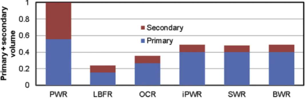
4.2.2. Capital cost
Fig. 7displays the relative size of the primary system com-bined with turbo machinery systems (advanced compact Rankine cycle) for the top five technologies relative to the reference design. The LBFR shows the most compact size followed by the OCR. Only accounting for the primary and secondary sides, the hull size savings are significant among all the designs relative to the base design.
The capital cost of an offshore design, depends on the hull space used as well as the simplicity of its systems. The costs per MWe of the LBFR and OCR are expected to be the least among the concepts due to their larger reduction in space requirements as listed inTable 3. The LBFR reactor section is 40% smaller than OCR but its high corrosion resistant mate-rials are far more expensive and, therefore, can be assumed more costly. While the SWR requires more expensive mate-rials for its core internals and steam line, its 2.5% higher thermodynamic efficiency could improve its levelized cost to be on a par with a BWR. The BWR/SWR are assumed to be more cost effective than the integrated PWR due to a much cheaper vessel and the elimination of steam generators for the same hull volume. The base design has the most costly hull.
4.2.3. Operating and maintenance cost
The operating and maintenance (O&M) cost plays an impor-tant role in operation of a reactor. The BWR and PWR are proven designs which operate with high capacity factors with well-defined maintenance needs. However, the integrated PWR innovations of the integral configuration and PCHEs are unproven. Similarly, the use of PCHEs for the OCR as well as the lack of recent experience for OCR operation results in large uncertainty for its operational performance. Although the LBFR is deemed reliable, it still lacks operational experience for power generation. The SWR is most likely to result in the highest O&M cost due to the lack of operation experience in terms of material performance with steam at 500C. With respect to refueling, the LBFR will require additional power to keep the LBE from freezing at all times, which will come at additional cost. In a larger view of the cost of power from
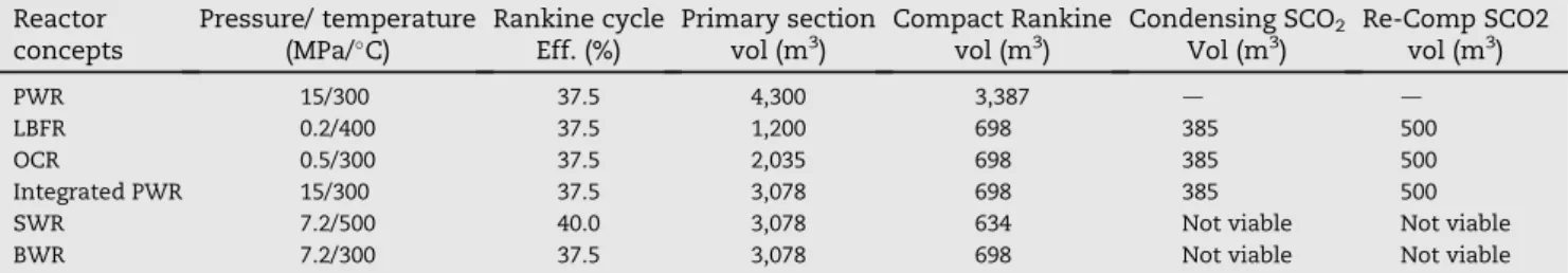
Table 3eThe metrics of each technology for different power cycle options (note: all technologies operate at 160 MWe).
Reactor concepts Pressure/ temperature (MPa/C) Rankine cycle Eff. (%) Primary section vol (m3) Compact Rankine vol (m3) Condensing SCO2 Vol (m3) Re-Comp SCO2 vol (m3) PWR 15/300 37.5 4,300 3,387 d d LBFR 0.2/400 37.5 1,200 698 385 500 OCR 0.5/300 37.5 2,035 698 385 500 Integrated PWR 15/300 37.5 3,078 698 385 500
SWR 7.2/500 40.0 3,078 634 Not viable Not viable
BWR 7.2/300 37.5 3,078 698 Not viable Not viable
BWR, boiling water reactor; LBFR, leadebismuth fast reactor; OCR, organic cooled reactor; PWR, pressurized water reactor; SWR, superheated water reactor.
nuclear systems, it must be mentioned that a large portion of the O&M cost results from fixed factors that are not influenced by the system design, such as security needs which is the same for all the concepts.
4.2.4. Overall
The base design is the only design that is fully ready for cur-rent deployment; therefore, a fair overall economic compari-son cannot be performed against the proposed designs. It is expected that the OCR and BWR technology results in the lowest overall cost, considering fuel cycle, capital, and O&M. The integrated PWR, SWR, and LBFR are expected to have similar cost levels. With recent improvements in material selection[33]and SCO2power cycle[38], by 2030e2040, the
LBFR concept could achieve 200e300C higher turbine inlet
temperatures and be coupled to an SCO2cycle that could boost
its efficiency resulting in making it the most economical design.
4.3. Dual-use resistance
From a fuel cycle perspective all the concepts display similar proliferation resistance levels by using < 20% enriched ceramic fuels. The risk of dual use of the proposed design for propulsion is of concern, since similar to military nuclear submarines, the reactor will not require refueling for long periods and can be transported long distances without re-surfacing. The vertical layout of the integrated PWR, BWR, and SWR will be more difficult to use for nuclear propulsion, since it is hydrodynamically less ideal than the horizontal hull orientation of the reference design. For dual use concerns, only the SWR and BWR designs have the desirable charac-teristics that they cannot be used for propulsion.
5.
Conclusion
An overview of nuclear reactor technologies was made based on a reference design priorities and constraints, and five potentially viable technologies were chosen from among 13 candidate designs. Two of the five had reference plants that can be used as-is for assessment, while for the remaining three technologies, new designs were developed as part of this design evaluation:
Integrated PWR: an integral PWR with PCHEs to achieve a more compact hull size while maintaining the safety standards required (indefinite coolability following acci-dents through passive safety systems).
SWR: a superheated BWR concept with higher thermody-namic efficiency due to its higher outlet temperature (500C) than a standard BWR[32].
OCR: a new OCR concept that has potential to require only half of the reference design's primary size while using less expensive material for the primary components[33]. The study of power cycle options concluded that the SCO2
cycles provided ~10 and ~2 times space savings over a tradi-tional and a compact Rankine cycle, respectively. However, in terms of primary and secondary total hull size, the SCO2cycles
result in approximately the same space as the turbomachinery design of the compact Rankine cycle. While the cost of the SCO2
components is expected to be cheaper, the R&D required to have a reliable system by 2030e2040 will be substantial. In
terms of compactness, the LBFR required the least space compared to the other designs, followed by the new OCR design. In terms of economics, the OCR and BWR designs are expected to be the most cost effective options. The LBFR economics could substantially improve with advancements in corrosion/erosion resistance materials and SCO2power cycle components.
Conflicts of interest
All authors have no conflicts of interest to declare.
Acknowledgments
Financial support for this work was provided by DCNS. The authors would like to thank the DCNS members, specially, Geoffrey Haratyk, for their feedback throughout this work. Lastly, this work was performed with the late Professor Mujid Kazimi at MIT; all the authors are eternally thankful to have had the pleasure to work with him for many years.
Nomenclature
BWR boiling water reactor CRD control rod drive
ISP internal suppression pool
IXAF internally and externally cooled annular fuel LBFR leadebismuth fast reactor
LOCA loss of coolant accident LWR light water reactor OCR organic cooled reactor PWR pressurized water reactor RPV reactor pressure vessel SCO2 supercritical CO2
SMR small modular reactor SWR superheated water reactor
r e f e r e n c e s
[1] G. Haratyk, C. Lecomte, F.X. Briffod, Flexblue®: a subsea and transportable small modular power plant, in: Proceedings of ICAPP, 2014. Charlotte, USA.
[2] J. Buongiorno, J. Jurewicz, M. Golay, N. Todreas, The offshore floating nuclear plant concept, Nucl. Technol. 194 (2016) 1e14.
[3] K. Shirvan, G. Haratyk, R. Ballinger, J. Buongiorno, C. Forsberg, M. Kazimi, N. Todreas, Advanced offshore seabed reactors, in: Proceedings of ICAPP, 2015. Nice, France. [4] M. Galvin, N. Todreas, L. Conway, Maintenance cycle
extension in the IRIS advanced light water reactor, Nucl. Technol. 143 (2003) 270e280.
[5] N. Yoshida, M. Kawakami, K. Hiraiwa, H. Heki, Study on long life core with uranium fuel for LSBWR, in: Proceedings of PHYSOR, 2002. Seoul, Korea.
[6] Y.C. Ko, M.S. Kazimi, Conceptual design of an annular-fueled superheat boiling water reactor, MIT-ANP-TR-130, MIT, Cambridge (MA), USA, 2010.
[7] G. Toshinsky, V. Petrochenko, Modular lead-bismuth fast reactors in nuclear power, Sustainability 4 (2012) 2293e2316.
[8] K. Shirvan, R. Ballinger, J. Buongiorno, C. Forsberg, M. Kazimi, N. Todreas, Advanced offshore seabed reactors, MIT-ANP-TR-155, MIT, Cambridge (MA), 2014.
[9] International Atomic Energy Agency (IAEA), Status of small and medium sized reactor designs, September 2011. [10] J. Buongiorno, J.W. Sterbentz, P.E. MacDonald, Study of solid
moderators for the thermal-spectrum supercritical water-cooled reactor, Nucl. Technol. 153 (2006) 282e303.
[11] E.D. Greaves, K. Furukawa, L. Sajo-Bohus, H. Barros, The case for the thorium molten salt reactor, Proc. Latin Am. Symp. Nucl. Phys. Appl. 1423 (2012) 453e460.
[12] C. Forsberg, D. Curtis, J. Stempien, R. MacDonald, P. Peterson, Fluoride-salt-cooled high-temperature reactor (FHR) commercial basis and commercialization strategy, MIT-ANP-TR-153, MIT, Cambridge (MA), USA, 2014.
[13] E.A. Hoffman, W.S. Yang, R.N. Hill, Preliminary core design studies for the advanced burner reactor over a wide range of conversion ratios, ANL-AFCI-177, ANL, Chicago, USA, 2006. [14] K. Kunitomi, S. Katanishi, S. Takada, T. Takizuka, X. Yan,
Japan's future HTR-the GTHTR300, Nucl. Eng. Design 233 (2004) 309e327.
[15] P. Anzieu, R. Stainsby, K. Mikityuk, Gas-cooled fast reactor (GFR): overview and perspectives, in: Proceedings of the GIF Symposium, 2009. Paris, France.
[16] P. Hejzlar, N.E. Todreas, E. Shwageraus, A. Nikiforova, R. Petroski, M.J. Driscoll, Cross-comparison of fast reactor concepts with various coolants, Nucl. Eng. Design 239 (2009) 2672e2691.
[17] M.A. Erighin, A 48 month extended fuel cycle for the B&W mPowerTMsmall modular nuclear reactor, in: Proceedings of
PHYSOR, 2012. Knoxville, USA.
[18] K. Shirvan, P. Hejzlar, M.S. Kazimi, The design of a compact integral medium size PWR, Nucl. Eng. Design 243 (2012) 393e403.
[19] J.M. Cronje, J.J. Van Wyk, M.J. Memmott, Overview of the Westinghouse small modular reactor building layout, in: Proceedings of ICAPP 2012, June 24e28, 2012. Chicago, USA.
[20] M.J. Memmott, A. Manera, The use of a flashing drum to generate steam in the integral, inherently safe (I2S) light water reactor, in: Proceedings of ICAPP 2014, 2014. Charlotte, USA. [21] HEATRICTM[Internet]. [cited 2008 Dec]. Available from:
http://www.heatric.com.
[22] G. Haratyk, K. Shirvan, M. Kazimi, Compact steam generator for nuclear application, Proceedings of NURETH16, 2015. Chicago, USA.
[23] Aspentech, ASPENONE V8 [Internet]. 2014. Available from:
http://www.aspentech.com/products/.
[24] S. Dewson, C. Grady, HEATRIC Workshop at MIT, Cambridge, MA, USA, 2003.
[25] Measuring Worth [Internet]. 2010. Available from:http:// www.measuringworth.com/uscompare/.
[26] KAERI, Status report 77dSystem-Integrated Modular
Advanced Reactor (SMART) [Internet]. Available from:, 2011
https://aris.iaea.org/sites/..%5CPDF%5CSMART.pdf. [27] H. Bae, D.E. Kim, S.U. Ryu, J.-S. Suh, An SBLOCA test of safety
injection line break with the SMART-ITL facility and its MARS-KS code simulation, in: Proceedings of ICAPP, 2014 paper 14140. [28] F. Incropera, Fundamentals of Heat and Mass Transfer, fifth
ed., John Wiley and Sons, New York, USA, 2002.
[29] D. Feng, P. Hejzlar, M.S. Kazimi, Thermalehydraulic design
of high-power-density annular fuel in PWRs, Nucl. Technol. 160 (2007) 16e44.
[30] Y.S. Yang, D.H. Kim, J.G. Bang, H.K. Kim, T.H. Chun, K.S. Kim, K.W. Song, C.G. Seo, H.T. Chae, Irradiation test of dual-cooled annular fuel pellets, in: Proceedings of WRFPM/Top Fuel, 2009. Paris, France.
[31] B.A. Pint, K.A. Terrani, M.P. Brady, T. Cheng, J.R. Keiser, High temperature oxidation of fuel cladding candidate materials in steamehydrogen environments, J. Nucl. Mater. 440 (2013)
420e427.
[32] K. Shirvan, M. Kazimi, Superheated water small modular underwater reactor concept, J. Nucl. Eng. Technol. 48 (2016) 1338e1348.
[33] M. Short, R.G. Ballinger, H.E. Hanninen, Corrosion resistance€ of alloys F91 and Fee12Cre2Si in leadebismuth eutectic up
to 715C, J. Nucl. Mater. 434 (2013) 259e281.
[34] P. Kasten, R. Adama, R. Carlsmith, R. Chapman, E. Epler, E. Gift, F. Harrington, M. Myers, R. Olson, J. Roberts, R. Solmon, J. Sanders, R. Stone, D. Vondy, C. Walker, T. Washburn, L. Yeatts, F. Zapp, An evaluation of heavy-water-moderated organic-cooled reactors, ORNL-3921, ORNL, Knoxville, USA, 1967. [35] M.T. Simnad, The U-ZrHx alloy: its properties and use in
TRIGA fuel, Nucl. Eng. Design 64 (1981) 403e422.
[36] P. Macdonald, J. Buongiorno, C. Davis, K. Weaver, R. Latanision, B. Mitton, G. Was, M. Carelli, D. Paramonov, L. Conway, Feasibility study of supercritical light water cooled fast reactors for actinide burning and electric power production, INEEL/EXT-02e00925, INL, Idaho Falls, USA, 2002.
[37] K. Shirvan, E. Forrest, Design of an organic simplified nuclear reactor, J. Nucl. Eng. Technol. 48 (2016) 893e905.
[38] S.A. Wrights, R.F. Radel, T.M. Conboy, G.E. Rochau, Modeling and experimental results for condensing supercritical CO2
power cycles, SAND2010-8840, Sandia National Lab, Albuquerque, USA, 2011.
[39] Siemens, ‘Industrial Steam Turbines: The comprehensive product range from 2 to 250 megawatts [Internet]. [cited 2013]. Available from:http://www.energy.siemens.com/us/ pool/hq/power-generation/steam-turbines/Industrial_ Steam_Turbines_en.pdf.