OPTIMIZATION IN MULTI-RELAY
WIRELESS NETWORKS
A Thesis Submitted
to the College of Graduate Studies and Research in Partial Fulfillment of the Requirements
for the Degree of Master of Science
in the Department of Electrical and Computer Engineering University of Saskatchewan
by
Duy H. N. Nguyen B. Eng. (Hons I)
Saskatoon, Saskatchewan, Canada
c
Permission to Use
In presenting this thesis in partial fulfillment of the requirements for a Postgraduate degree from the University of Saskatchewan, it is agreed that the Libraries of this University may make it freely available for inspection. Permission for copying of this thesis in any manner, in whole or in part, for scholarly purposes may be granted by the professors who supervised this thesis work or, in their absence, by the Head of the Department of Electrical and Computer Engineering or the Dean of the College of Graduate Studies and Research at the University of Saskatchewan. Any copying, publication, or use of this thesis, or parts thereof, for financial gain without the written permission of the author is strictly prohibited. Proper recognition shall be given to the author and to the University of Saskatchewan in any scholarly use which may be made of any material in this thesis.
Request for permission to copy or to make any other use of material in this thesis in whole or in part should be addressed to:
Head of the Department of Electrical and Computer Engineering 57 Campus Drive
University of Saskatchewan
Saskatoon, Saskatchewan, Canada S7N 5A9
Acknowledgments
Over the years, I have been fortunate to have the experience working with and getting support from many great persons. A few lines here are certainly not enough to express my sincere appreciation to all of them.
First of all, I would like to gratefully acknowledge and express a sincere thank you to my supervisor, Professor Ha Hoang Nguyen for his invaluable support and guidance during my studies at the University of Saskatchewan. I am truly privileged to have learned from his remarkable technical knowledge and research enthusiasm. He has not only introduced and taught me many aspects of the interesting field of wireless communications, but also laid down the path for me to keep exploring new knowledge in the field. This thesis would not be finished without his support and encouragement.
I would like to thank Professor Hoang Duong Tuan of University of New South Wales, NSW, Australia for his collaboration on various works in optimization theory. His deep and thorough knowledge in optimization theory has helped bring to light to collaborated works with him.
I am also grateful to Dr. Jochen Trumpf of Research School of Information and System Engineering, Australian National University (ANU), ACT, Australia, for his encouragement to my pursuit of higher education in North America. His guidance during the exciting summer of 2004-2005 at ANU has definitely boosted my confidence in pursuing research in the electrical engineering field.
I would like to say thank you to my two longtime friends back to the days in Australia: Khoa (Kevin) T. Phan of California Institute of Technology, and Quoc V. Le of Stanford University. The endless discussions on various topics in communication and networking theories with Khoa have inspired me to lots of open problems in the fields. With Quoc, I have had a great pleasure to talk with him about optimization theory, which has helped me to get more in-depth understanding to the theory.
I would like to thank all my labmates: Tung, Nam, Ha, Zohreh, Simin, and Quang for the wonderful time at the Communication Theory Research Group (CTRG).
My deepest love and gratitude is devoted to all of my family members: Mom and Dad, brothers Khanh and Ngoc, sister-in-law Huong, and beloved niece Giang, who always support me in each and every endeavor in my life. I truly owe all of my successes to them. A special thank you must go to my girlfriend, Ngan, for her love, support, and tenderness. I enjoy every single moment talking with her, planning our future, and I look forward to having her on the long journey ahead.
Finally, I would not forget to gratefully acknowledge the NSERC Discovery Grant and the Department of Electrical and Computer Engineering, University of Saskatchewan for the financial support of my studies.
Abstract
The concept of cooperation in communications has drawn a lot of research atten-tion in recent years due to its potential to improve the efficiency of wireless networks. This new form of communications allows some users to act as relays and assist the transmission of other users’ information signals. The aim of this thesis is to ap-ply optimization techniques in the design of multi-relay wireless networks employing cooperative communications. In general, the thesis is organized into two parts: “Dis-tributed space-time coding” (DSTC) and “Dis“Dis-tributed beamforming”, which cover two main approaches in cooperative communications over multi-relay networks.
In Part I of the thesis, various aspects of distributed implementation of space-time coding in a wireless relay network are treated. First, the thesis proposes a new fully-diverse distributed code which allows noncoherent reception at the destination. Second, the problem of coordinating the power allocation (PA) between source and relays to achieve the optimal performance of DSTC is studied and a novel PA scheme is developed. It is shown that the proposed PA scheme can obtain the maximum diversity order of DSTC and significantly outperform other suboptimal PA schemes. Third, the thesis presents the optimal PA scheme to minimize the mean-square error (MSE) in channel estimation during training phase of DSTC. The effect of imperfect channel estimation to the performance of DSTC is also thoroughly studied.
In Part II of the thesis, optimal distributed beamforming designs are developed for a wireless multiuser multi-relay network. Two design criteria for the optimal distributed beamforming at the relays are considered: (i) minimizing the total relay power subject to a guaranteed Quality of Service (QoS) measured in terms of signal-to-noise-ratio (SNR) at the destinations, and (ii) jointly maximizing the SNR margin at the destinations subject to power constraints at the relays. Based on convex optimization techniques, it is shown that these problems can be formulated and solved via second-order conic programming (SOCP). In addition, this part also proposes simple and fast iterative algorithms to directly solve these optimization problems.
Table of Contents
Permission to Use i Acknowledgments ii Abstract iv Table of Contents v List of Tables ix List of Figures xList of Abbreviations xiv
1 Introduction 1
1.1 Thesis Contribution and Outline . . . 8
1.2 Notations . . . 11
I
Distributed Space-Time Coding
13
2 Distributed Space-Time Coding: Design Criteria and Performance
Analysis 14
2.1 Introduction . . . 14
2.2 System Model . . . 16
2.3 Distributed Space-Time Coding in Coherent Relay Networks . . . 19
2.4 Distributed Unitary Space-Time Modulation in Partially Coherent and Noncoherent Relay Networks . . . 22
2.4.1 ML Receiver for DUSTM over the Partially Coherent Relay Network . . . 24
2.4.2 GLRT Receiver for DUSTM over the Noncoherent Relay Network 25
2.4.3 PEP of DUSTM over the Partially Coherent Relay Network . 26
2.4.4 PEP of DUSTM over the Noncoherent Relay Network . . . 28
2.4.5 Impact of Non-functioning Relays . . . 29
2.5 Simulation Results . . . 30
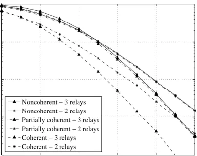
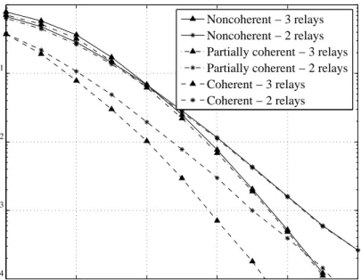
2.5.1 Performance Comparison of DUSTM over Partially Coherent, Noncoherent, and Coherent Networks . . . 31
2.5.2 Comparison Between DUSTM and a Random Code . . . 34
2.6 Summary . . . 35
3 Optimal Power Allocation in DSTC 36 3.1 Introduction . . . 36
3.2 Problem Formulation . . . 37
3.3 SNR-Maximized PA in Balanced Networks . . . 40
3.4 SNR-Maximized PA in Unbalanced Networks . . . 41
3.5 The Optimal PA Scheme under the Amount of Fading Constraint . . 45
3.6 Diversity Analysis of The Proposed Power Allocation Scheme . . . 48
3.6.1 Coherent DSTC . . . 48
3.6.2 Partially Coherent and Noncoherent DSTC . . . 50
3.7 Simulation Results . . . 51
3.8 Summary . . . 55
4 Optimal Training and Mismatched Decoding in DSTC 56 4.1 Introduction . . . 56
4.2 Optimal Training Design and Channel Estimation . . . 57
4.2.1 Maximum Likelihood (ML) Estimation . . . 58
4.2.2 Minimum Mean-Square Error (MMSE) Estimation . . . 61
4.2.3 Examples of Training Design . . . 62
4.3 Performance of Mismatched Decoding . . . 63
4.4 Simulation Results . . . 66
4.5 Summary . . . 69
II
Distributed Beamforming
70
5 Distributed Beamforming in a Multiuser Multi-relay Network with Guaranteed QoS 71 5.1 System Model . . . 735.2 Sum-Power Minimization . . . 75
5.3 Sum-Power Minimization with Per-Relay Power Constraints . . . 80
5.3.1 Beamforming Duality . . . 83
5.3.2 An Interpretation via a Virtual Uplink Channel . . . 85
5.3.3 Numerical Algorithm . . . 89
5.4 Simulation Results . . . 91
5.5 Summary and Future Works . . . 94
6 SNR Maximization and Distributed Beamforming in a Multiuser Multi-relay Network 96 6.1 Sum-Power Constraints . . . 97
6.1.2 Convex Solution . . . 98
6.1.3 Modified Fixed Point Iteration for Finding p? n . . . 100
6.2 Per-Relay Power Constraints . . . 100
6.2.1 Bisection Method . . . 101
6.2.2 An Iterative Algorithm for Finding w? n . . . 102
6.3 Simulation Results . . . 104
6.4 Summary and Future Works . . . 107
7 Concluding Remarks 109 A Space-Time Coding 111 A.1 Coherent Space-Time Coding . . . 112
A.2 Noncoherent Space-Time Coding . . . 115
B Convex Optimization Theory 119 B.1 Convex Sets and Convex Functions . . . 120
B.1.1 Convex Sets . . . 120
B.1.2 Convex Functions . . . 122
B.2 Convex Optimization . . . 124
B.2.1 Classes of Convex Optimization . . . 124
B.2.2 Lagrangian Duality . . . 125
B.3 Projection on a Set . . . 128
List of Tables
List of Figures
1.1 A typical transmission wireless environment. . . 2
1.2 Illustration of spatial diversity in an uplink channel. . . 5
1.3 Example of a relay channel. . . 6
1.4 Amplify-and-forward and decode-and-forward protocols. . . 7
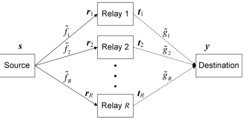
2.1 Block diagram of a distributed space-time coding system with R+ 2 nodes. . . 17
2.2 Symbol error performance of DUSTM withσ2 F = 1 andσG2 = 1. . . . 32
2.3 Symbol error performance of DUSTM withσ2 F = 10 and σG2 = 1. . . . 32
2.4 Symbol error performance of DUSTM withσ2 F = 1 andσG2 = 10. . . . 33
2.5 Symbol error performances of the proposed DUSTM and a random code withσ2 F = 1 andσG2 = 10. . . 34
3.1 The relays’ locations relatively to the source and destination. . . 51
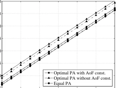
3.2 Average SNR at the destination with different PA schemes. “Dash-dot” lines are for the exact SNR evaluation, solid lines are for the SNR evaluated by (3.4). . . 52
3.3 Performance of noncoherent DUSTM with different PA schemes. “Dash-dot” lines are for the three-relay system, solid lines are for the two-relay system. . . 53
3.4 Performance of coherent DSTC with different PA schemes. “Dash-dot” lines are for the three-relay system, solid lines are for the two-relay system. . . 54
4.1 Total MSE achieved with ML and MMSE estimators, with the optimal and equal PA schemes in a four-relay network. . . 67
4.2 Error performance of DSTC with different types of detection in a two-relay network. “Dash-dot” lines are for the optimal PA scheme, solid lines are for the equal PA scheme. . . 67
4.3 Error performance of DSTC with different types of detection in a four-relay network. “Dash-dot” lines are for the optimal PA scheme, solid lines are for the equal PA scheme. . . 68
5.1 Block diagram of a distributed beamforming system withR relays and
N users. . . 73 5.2 Sum relay power minimization for the nth user. . . 76 5.3 Sum relay power minimization with per-relay power constraints. . . . 81
5.4 Block diagram of a virtual SIMO uplink channel. . . 86
5.5 Power consumptions at the relays over 50 channel realizations with different power constraints: with per-relay power constraints (solid lines), without per-relay power constraints (“dash-dot” lines). . . 92
5.6 Convergence of the iterative fixed point algorithm (5.19) with different starting points and the achievable SNR at user-1’s destination after each iteration. . . 93
5.7 Convergence of the proposed algorithm in finding the optimal dis-tributed beamformers with per-relay power constraints. . . 94
6.1 The achievable SNR margin τ and the power consumptions at the relays over 50 channel realizations with different power constraints: with per-relay power constraints (solid lines), and without per-relay power constraints (“dash-dot” lines). . . 105
6.2 Convergence of the relay power for each user and the corresponding achievable SNR at each user’s destination by the modified iterative fixed point algorithm. . . 106
6.3 Convergence of the proposed algorithm in finding the optimal dis-tributed beamformers with per-relay power constraints to jointly max-imize the SNR margin. . . 106
A.1 Block diagram of a space-time coding system. . . 111
A.2 The encoding and transmission of an Alamouti codeword. . . 114
B.1 Example of an affine set: a line passing throughx1 and x2. Any point,
described by θx1+ (1−θ)x2, where θ varies over R, lies on the line. . 120
B.2 Examples of convex and nonconvex sets: the hexagon and the circle are convex, whereas the the boomerang is not. The line segment between the two points in the “boomerang” set (shown as dots) is not contained in the set. . . 120
B.3 Example of a cone: the pie slice shows all points of the formθ1x1+θ2x2,
where θ1, θ2 ≥0. . . 121
B.4 Boundary of second-order cone inR3 :n(x
1, x2, t)|(x21+x22)1/2 ≤t o
. . 121
B.5 Boundary of positive semidefinite cone inS2. . . 122
B.6 Graph of a convex function. The line segment between any two points on the graph lies above the graph. . . 123
B.7 Graph of a quasiconvex function on R. The sublevel set Sα is the interval [b, c], which is convex. The sublevel set Sβ is the interval [a,∞), which is also convex. . . 124
B.8 Lower bound from the Lagrangian dual function. The solid curve is the objective function f0, and the dashed curve is the constraint function
f1. The feasible set is the interval [−1,1], indicated by the two
“dash-dot” vertical lines. The optimal point and value arex? =−1,p? =−2. The dot curves showL(x, λ) forλ= 0.2,0.6,1.0, . . . ,2.6. Each of these has a minimum value smaller than p?, since on the feasible set and for
λ≥0, we have L(x, λ)≤f0. . . 127
B.9 Dual function g(λ) for the problem in Figure B.8. f0 is not convex,
but the dual function is strictly concave. The horizontal dashed line shows p?, which is the upper-bound on g(λ). Strong duality holds in this problem, as the maximum value d? of g(λ) satisfies d? =p?. . . . 128 B.10 Examples of projection in 2-D and 3-D vector spaces. . . 130
Abbreviations
4G Fourth Generation
AF Amplify-and-Forward
AWGN Additive White Gaussian Noise
CSI Channel State Information
CSNR Channel Signal-to-Noise-Ratio
dB Decibel
DF Decode-and-Forward
DFT Discrete Fourier Transform DSTC Distributed Space-Time Coding DUSTM Distributed Space-Time Modulation GLRT Generalized Likelihood Ratio Test FDMA Frequency Division Multiple Access
KKT Karush-Kuhn-Tucker
LP Linear Programming
MIMO Multiple-Input Multiple-Output
ML Maximum Likelihood
MMSE Minimum Mean-Square Error
MSE Mean-Square Error
OFDM Orthogonal Frequency Division Multiplexing OSTBC Orthogonal Space-Time Block Code
pdf Probability Density Function PEP Pairwise Error Probability
QCQP Quadratically Constrained Quadratic Programming
QoS Quality of Service
QOSTBC Quasi-Orthogonal Space-Time Block Code
QP Quadratic Programming
SDP Semidefinite Programming
SER Symbol-Error-Rate
SIMO Single-Input Multiple-Output
SINR Signal-to-Interference-plus-Noise-Ratio
SNR Signal-to-Noise-Ratio
SOC Second-Order Cone
SOCP Second-Order Conic Programming
SR Selection Relaying
ST Space-Time
STC Space-Time Coding
TDMA Time Division Multiple Access USTM Unitary Space-Time Modulation
1. Introduction
In recent years, the rapid expansion of wireless communications has put a signif-icant pressure to the current wireless network infrastructure to cope with demands for higher throughput, higher robustness and better coverage. It is expected that such demands would even be stronger in the future fourth-generation (4G) wireless networks. No longer limited to a medium for only voice transmission, wireless com-munications have assumed an important role in transmitting data at higher rates and streaming multimedia services, such as video, at higher Quality of Service (QoS) requirements as well. These demands have posed tough technical challenges for the current and future wireless networks.
A fundamental aspect of wireless communication that makes the design of robust wireless networks challenging is the phenomenon of fading. Basically, fading in a wireless channel refers to the time and frequency variations of the channel quality. The fading effect of a wireless channel can be categorized into two types: large-scale fading, and small-scale fading [1]. The large-scale fading is due to the signal attenuation as a function of distance and shadowing effects caused by large objects such as buildings, hills, obstacles, etc. The small-scale fading is due to the constructive and destructive interferences of the multiple paths between the transmitter and receiver. How to deal with fading, especially the small-scale fading, is critical to the design of any robust wireless communication system.
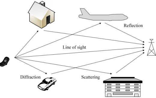
As illustrated in Figure 1.1, the received signal in a wireless channel is a compos-ite of the transmitted signal over several different paths due to reflection, diffraction, and scattering from buildings, moving objects like cars, trees, etc. When there is a
Scattering Diffraction
Reflection Line of sight
Figure 1.1 A typical transmission wireless environment.
large number of scatterers that contribute to the signal at the receiver, the central limit theorem leads to a Gaussian process model for the channel coefficient. If the process is zero-mean, the absolute value of the channel response at any time instant has a Rayleigh probability distribution. Mathematically, given x[m] as the trans-mitted signal, the received signal y[m] over a fading channel (in discrete base-band representation) at time m is given by
y[m] = h[m]x[m] +z[m], (1.1) where z[m] is the additive white Gaussian noise (AWGN), and h[m] is the channel coefficient, which is commonly referred to as the “channel state information” (CSI). In a typical Rayleigh fading model of the wireless channel,h[m] is a zero-mean circularly symmetric complex Gaussian random variable.
It is noted that in an AWGN channel, where h[m] = 1, errors in detection occur due to the additive noise componentz[m]. Uncoded signaling schemes, such as binary phase-shift keying (BPSK), can perform very well in an AWGN channel, where the detection error decays exponentially with the signal-to-noise ratio (SNR) [1]. On the other hand, in a fading channel, the BPSK signaling scheme fails completely even in
the absence of noise if the receiver has no knowledge of channel coefficienth[m]. This is because there is nothing in the received signaly[m] which can be used to distinguish the transmitted signal x[m]. As the phase of the channel coefficienth[m] is uniformly distributed between 0 and 2π, the phase ofy[m] is also uniformly distributed between 0 and 2π. Furthermore, the amplitude of y[m] is independent of the transmitted BPSK symbol x[m].
Suppose now that the channel coefficient is tracked such that it is known at the receiver. This can be practically done by sending a known sequence (called training), and performing “channel estimation” at the receiver using the training sequence. As a result, coherent detection can be performed as in the case with an AWGN channel. Even so, the communication scheme over the fading channel still suffers from a much poorer performance than that over the AWGN channel [2]. This is due to the fact that the channel gain is random and there is a certain probability that the channel is “in a deep fade” [1]. More specifically, when the channel attenuation is large (the amplitude of the channel coefficient is small), the low instantaneous received SNR leads to a high probability in detection error.
However, if the receiver is provided with several replicas of the same informa-tion signal transmitted over independent fading channels, the probability that all the received signal components are in deep fades simultaneously is much smaller. This approach to combat fading, called “diversity technique”, has been commonly applied in wireless communications. In order to quantify the effectiveness of a diversity tech-nique, the relationship between the average SNR and the average error probability
Pe is determined. A common measure is the “diversity order”, defined as follows:
Gd=− lim
SNR→∞
logPe
log SNR. (1.2)
Obviously, the higher the diversity order is, the more reliable the wireless communi-cation system is. There are several approaches to provide diversity techniques in a wireless system as outlined next. Regardless of the approach used, it is important that the implemented technique is capable of obtaining the system’s “maximum di-versity order”. More precisely, the didi-versity technique should take the full advantage
of the multiple independent received copies of the same transmitted signal.
One diversity technique is to transmit the same information signal over multiple frequency bands, where the separation between successive bands equals or exceeds the coherence bandwidth of the channel. Here, the coherence bandwidth measures the frequency range over which the channel responses are correlated. This technique is calledfrequency diversity. A second technique to obtain independently faded versions of the same information signal is to transmit the signal in different time slots, where the separation between successive time slots equals or exceeds the coherence time of the channel. Here, the coherent time refers to the time duration over which the channel responses are correlated. This technique is known as time diversity. It is noted that both frequency and time diversity techniques are inefficient since frequency diversity requires bandwidth expansion, whereas time diversity needs extra time slots for transmission. Another popular approach to obtain diversity is to deploy multiple antennas in reception and/or transmission. This technique is called spatial diversity. Spatial diversity, albeit requiring extra costs for multiple antenna deployment, is much more spectral efficient and can overcome the drawbacks of both frequency diversity and time diversity.
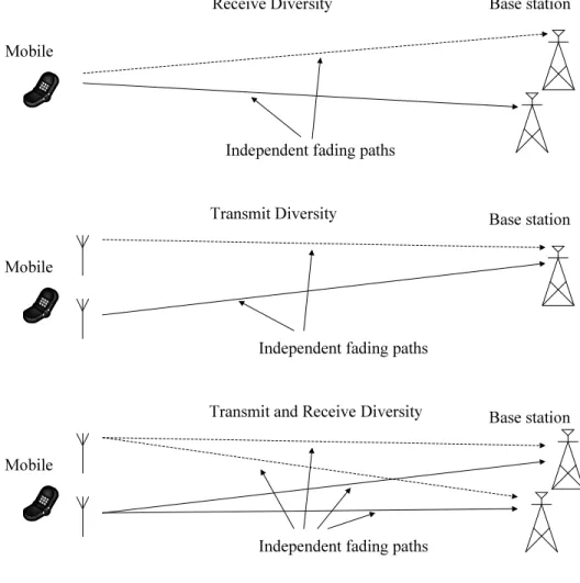
Figure 1.2 demonstrates examples of providing spatial diversity in an uplink chan-nel from a mobile unit to a base station. Spatial diversity can be obtained by deploy-ing multiple antennas at the receivdeploy-ing end, referred to as receive diversity, or at the transmitting end, referred to as transmit diversity, or a combination of both. While it is straightforward to realize receive diversity by simple combining techniques at the receiver, such as the maximal ratio combining (MRC), achieving transmit diversity requires a more complex technique at the transmitter [1]. The recent invention of
space-time coding [3, 4] (in the 1990s) allows a simple, yet elegant method to obtain transmit diversity with a very high bandwidth efficiency. In addition, space-time coding is capable of achieving the maximum diversity order of the multiple-antenna system. These recent developments in multi-input multi-output (MIMO) systems have been a significant step forward with a lot of potentials in meeting the technical
Independent fading paths Mobile
Base station Independent fading paths
Mobile
Base station Receive Diversity
Transmit Diversity
Independent fading paths Mobile
Base station Transmit and Receive Diversity
Figure 1.2 Illustration of spatial diversity in an uplink channel.
challenges of the current and next generation of wireless communications. However, the implementation of multiple antennas at mobile units faces a serious technical challenge due to the size and power limitation of the mobile units. This is because the multiple antennas have to be placed several wavelengths apart so that the channel between each transmit and receive antenna experiences independent fading.
More recently, cooperative communication has been proposed to provide a different implementation of multiple antennas which can allow future communication systems to overcome the aforementioned drawback [5]. In this new form of communications, the single-antenna users (or nodes) cooperate to relay each other’s information signals, create a virtual array of transmit antennas, and, thus achieve spatial diversity. Such cooperation can significantly improve the reliability of signal transmission from each
user [6]. User cooperation also enables the system to enhance its capacity and extend its coverage [7]. Due to the tremendous potential of cooperative communication, there has been a lot of research efforts in the last few years to study both the theoretical performance and practical implementation of this new communication scheme.
Independent fading paths Source
Relay
Destination
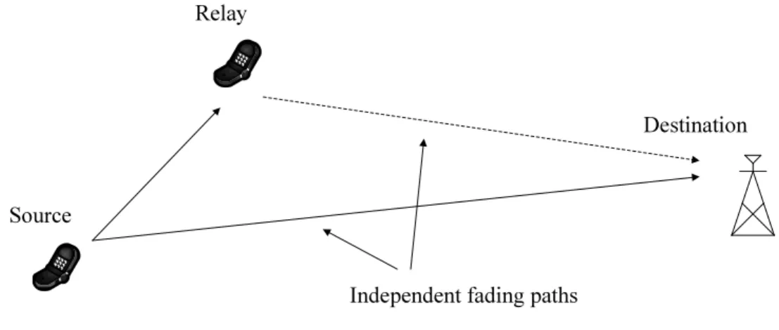
Figure 1.3 Example of a relay channel.
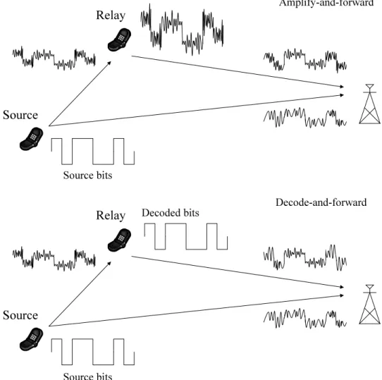
Figure 1.3 illustrates an example of cooperative communication in its simplest form. In particular, one user, called the source user, wants to send its information signal to another user, called the destination user. Another user, which acts as the relay, also receives the transmitted signal. The relay processes the received signal in some way, and then retransmits to the destination. As a result, the original sig-nal experiences independent transmissions from the source to destination. At the relay, several relaying protocols, e.g., amplify-and-forward (AF), decode-and-forward (DF) [5], could be applied toprocess the received signal. As its name suggests, in AF protocol, the relay simply amplifies the received signal and then forwards to the desti-nation. On the other hand, in DF protocol, the relay first decodes the received signal, re-encodes it, and then forwards to the destination. Figure 1.4 visually describes the AF and DF protocols at the relay.
In general, multiple relays could simultaneously assist the transmission from a source to a destination. Each relay could employ a dedicated channel to retransmit its received signal to the destination. However, this method is spectrally inefficient since it requires the number of dedicated channels to be at least equal to the number
Amplify-and-forward Decode-and-forward Decoded bits Source bits Source bits Source Relay Source Relay
Figure 1.4 Amplify-and-forward and decode-and-forward protocols.
of relays. In [8], a new cooperative strategy using AF protocol, referred to as “dis-tributed time coding” (DSTC), was proposed, where the conventional space-time coding designed for co-located antennas was implemented between the relays in a distributed manner. The new strategy allows a space-time transmission of source signals to the destination on the same channel and at the same time, and hence is more spectrally efficient. In addition, the new scheme is capable of obtaining the maximum diversity order promised by cooperative communications. Various aspects of the new cooperative strategy have led to many interesting research problems, such as code designs and performance analysis [8–10]. The main focuses of Part I of this thesis are to study fully-diverse code designs for DSTC with different types of CSI assumptions of the relay networks, optimal power allocation (PA) schemes between
the users, channel estimation, and performance analysis of mismatched decoding in DSTC.
It should be noted that DSTC can be implemented without the need of full channel state information (CSI) at the relays. However, should the CSI be available at the relays, i.e., each relay knows the CSI of the channel links connected to it, the relays can and should compensate for the phase changes introduced by the channels. As a result, the received signal at the destination can be coherently constructed. Such relaying strategy, known as “distributed beamforming”, was first proposed in [11–14]. The works in [11–14] study the optimal distributed beamforming strategies to either maximize the signal-to-noise (SNR) at the destination subject to power constraints as the relays or minimize the total relay power subject to the QoS requirement at the destination. Motivated by the early works on distributed beamforming in a one-source one-destination network, Part II of this thesis generalizes the distributed beamforming designs to a multi-source multi-destination network. By applying convex optimization techniques, this second part of the thesis proposes resource allocation schemes at the relays in order to optimally assist multiple source-destination pairs.
1.1
Thesis Contribution and Outline
The thesis is divided into two main parts, titledDistributed space-time coding and
Distributed beamforming, and is organized as follows.
Part I of the thesis, comprises Chapters 2, 3, and 4, is concerned with several important aspects of DSTC, including code designs, performance analysis, power al-location, channel estimation, and mismatched decoding. An important characteristic of DSTC is that it allows the destination to exploit cooperative diversity without the availability of CSI at the relays. Chapter 2 considers the design of DSTC in wire-less multi-relay networks with different CSI assumptions at the destination. First, the chapter reviews the DSTC design criteria in coherent relay networks. It then presents the design and the performance analysis of DSTC when full CSI at the des-tination is unavailable. Proposed in the chapter is a new fully-diverse distributed
code for the partially coherent and the noncoherent relay networks. The proposed distributed unitary space-time modulation (DUSTM), which relies on Fourier-based USTM, allows noncoherent detection at the destination. Developed are the maximum likelihood (ML) receiver for DUSTM over partially coherent relay networks and the generalized likelihood-ratio test (GLRT) receiver for the noncoherent relay networks. Performance analysis of the DUSTM over the two types of relay networks reveals a surprising result that the knowledge of the relay-to-destination channel information has a very little impact on the code performance.
Chapter 3 considers the optimal PA problem for DTSC based on the second-order statistics of each source-to-relay (S →R) and relay-to-destination (R→D) channels, subject to a total power budget at the source and relays. The chapter first examines the optimal PA scheme to maximize the effective average SNR in an arbitrary relay network. Interestingly, it shows that maximizing the average SNR is not sufficient to optimize the performance of the DSTC. More specifically, at the optimal solution for such a PA scheme, some of the relays might not be active, and thus compromise the distributed code’s full diversity order. It then introduces the concept of amount of fading to the relay networks and establishes the condition of the transmitted power at each relay such that the fading statistics of each S → R → D link is balanced. A novel and simple PA scheme is proposed at the chapter’s end and proved to be capable of obtaining the maximum diversity order in coherent, partially coherent, and noncoherent DSTC systems at high SNR. Finally, simulation results are given to confirm the analysis and show a significant performance improvement by the proposed PA scheme.
Chapter 4 is concerned with the optimal design in the training phase and the impact of channel estimation and mismatched decoding on DSTC. The chapter first makes use of the results in [15] that orthogonal training is optimal to minimize the total mean-square error (MSE) for both the maximum likelihood (ML) and minimum mean-square error (MMSE) estimations. It then studies an optimal PA scheme to further minimize the total MSE for both the estimation schemes. The result shows
that the optimal PA scheme is the same as that obtained in Chapter 3 under the minimum amount of fading constraint. The impact of imperfect channel estimation on the error performance of DSTC is also analyzed and it is proved that the mismatched decoding of DSTC is able to achieve the same diversity order as the coherent decoding of DSTC.
Part II of the thesis, consists of Chapters 5 and 6, is devoted to multi-source multi-destination networks employing distributed beamforming. An important re-mark about distributed beamforming is that it requires full CSI knowledge at the relays to perform beamforming. Two main problems in optimal distributed beam-forming designs addressed in this part are (i) minimize the total relay power with guaranteed QoS in terms of SNR at the destinations, and (ii) jointly maximize the SNR margin at the destinations subject to power constraints at the relays. The problems are sequentially investigated and shown to be closely related to each other.
Chapter 5 studies optimal distributed beamforming designs to minimize the total relay power with guaranteed QoS. The chapter exploits convex optimization tech-niques to find the optimal beamformers in a relay network with or without per-relay power constraints. First, the chapter shows that these problems can be formulated and solved via second-order conic programming (SOCP). Although the optimal solu-tions to the problems can be obtained by any conic solution package, the contribution of this chapter is a proposal of simple and fast iterative algorithms to efficiently solve them. The feasibility conditions of the two optimization problems are also studied in the chapter. With different assumptions on orthogonality in S → R and R → D
transmission phases, several potential future works on distributed beamforming de-signs are recommended at the chapter’s end.
Chapter 6 studies the distributed beamforming problems that are inverse to the ones in Chapter 5. With the constraints on either the sum relay power or the per-relay power, optimal distributed beamforming designs are studied to jointly maximize the SNR margin at the destinations. Although the two optimization problems can be solved effectively by the bisection methods via SOCP feasibility problems, the chapter
proposes two simple and fast iterative algorithms to directly solve the two problems without the need of a standard conic solution package. Future works on sum-rate maximization of the relay networks are also suggested.
Chapter 7 draws the conclusion and gives suggestions for further studies.
1.2
Notations
The notations in this thesis are quite standard and explained as follows:
• R and C denote the sets of real and complex numbers, respectively.
• A column vector is formatted in lower-case and bold, e.g., x; whereas a matrix is in upper-case and bold, e.g., A.
• Sn denotes the set of symmetric n×n matrices, whereas Sn
+ denotes the set of
symmetric positive semidefinite matrix. A∈Sn
+ is denoted as Aº0.
• IM stands for the M ×M identity matrix.
• diag(d1, d2, . . . , dM) denotes an M×M diagonal matrix with diagonal elements
d1, d2, . . . , dM.
• det(·) and tr(·) denote the determinant and trace of a square matrix, respec-tively.
• [x]i denotes the ith element of the column vector x, whereas [A]ij denotes the element at row i, column j of matrix A.
• Superscripts (·)T, (·)∗, (·)H, and (·)† stand for transpose, complex conjugate,
complex conjugate transpose, and matrix pseudo-inverse operations, respec-tively.
• Ex[·] and varx[·] indicate the expectation and variance of random variable x, respectively; whereas x? denotes the optimal value of variable x.
• CN(0, σ2) denotes a circularly symmetric complex Gaussian random variable
with variance σ2.
Part I
2. Distributed Space-Time Coding: Design
Criteria and Performance Analysis
2.1
Introduction
Distributed space-time coding (DSTC) [6, 8, 9, 18] refers a cooperative strategy, where the conventional space-time coding for co-located antennas is implemented be-tween the relays in a distributed manner. More specifically, when the source signal is received at the relays, it is linearly processed and then retransmitted to the destina-tion in the form of a space-time codeword. Like the convendestina-tional space-time coding in MIMO systems, where transmit diversity is exploited without the need of CSI at the transmitter (see Appendix A), DSTC in a wireless relay network allows the relays to exploit cooperative diversity without the availability of CSI at the relays. As a result, it is well known that the transmission reliability of the source signal over the relay network can be significantly improved.
In the last few years, there has been a lot of research studies in DSTC, for both AF and DF protocols. With the DF protocol, DSTC was first studied in [6,10,19]. In [19], the authors present a new type of distributed space-time block codes (DSTBC) for wireless networks with a large number of users, where each user is assigned a unique signature vector. With the AF protocol, DSTC has been investigated in [8–10,20–22]. Performance analysis and design criteria of DSTC are thoroughly studied in [8, 10].
It is noted that most of the works on cooperative communications in the literature assume the availability of perfect channel state information (CSI) of all the channels
at the relays and/or destination, and only a few of them have considered the scenarios where only imperfect channel estimation or no CSI is available. Reference [23] in-vestigated the noncoherent and mismatched coherent detectors for distributed STBC with one relay, where it is shown that the system can achieve a diversity order of 2. However, the derivations (see (19) and (20) in [23]) for the suboptimal receiver in the noncoherent detection turn the problem into the partially coherent one. The partially coherent relay network was investigated in detail in [22], where a differential coding scheme was proposed to take advantage of the cooperative diversity. For noncoherent relay networks, a fully-diverse distributed coding scheme based on division algebra was proposed in [20, 21]. Similar to the work in [8], references [20–22] consider AF protocol with linear processing at the relays.
Noncoherent reception for DSTC was also proposed in [24], where the decode-and-forward (DF), selection relaying (SR), incremental DF, and incremental SR protocols were employed, and USTM was implemented in a distributed fashion among the relays. A similar approach using DF protocol was also reported in [19, 25]. However, the drawback with these approaches is that the relay only forwards if it decodes the source signal correctly in the SR protocol, or it always forwards in the DF protocol. Given the random nature of the channels in wireless relay networks, for instance, when the channels between the source and some of the relays are bad, it is highly probable that the relays would decode incorrectly and thus not forward in the SR protocol, or forward the incorrect version of the source signal in the DF protocol. This will compromise the diversity advantage of DSTC. Moreover, the incremental DF and incremental SR require feedback from the destination to all the relays. The AF protocol is generally preferred to other protocols since it is always able to achieve the maximum diversity order and feedback from the destination is not required. Moreover, the AF protocol requires much less delay tolerance and infers no security problem as in the DF procotol.
This chapter focuses on the DTSC design in wireless relay networks with the AF protocol. The first part of the chapter reviews the DSTC with full CSI at the
desti-nation, i.e., coherent relay networks. From the performance analysis of the DSTC in coherent networks, the design criteria of a good DSTC scheme are then presented. It will be shown that the space-time code that achieves the full diversity and maximum coding gain in traditional MIMO systems also achieves the diversity order in DSTC implementation. This chapter then concentrates on the design and performance anal-ysis of DSTC over the partially coherent networks (only relay-to-destination CSI is available) and the noncoherent networks (no CSI is available). It shows how to in-corporate the Fourier-based USTM into wireless relay networks in a distributed man-ner. Developed are the maximum likelihood (ML) receiver for the distributed USTM (DUSTM) over partially coherent relay networks and the generalized likelihood-ratio test (GLRT) receiver for the noncoherent relay networks. Performance comparison of the DUSTM over the two types of relay networks reveals that, although the knowl-edge of relay-to-destination channels improves the symbol error rate (SER) compared to the case of fully noncoherent networks, this advantage diminishes as the total sys-tem power becomes large enough. In fact, it is shown that their performances are asymptotically the same when all the relays are active. The full diversity order, equal to the number of relays, is achievable in both networks if the coherence time is larger than twice the number of relays.
2.2
System Model
Consider a wireless relay network with R+ 2 nodes, as illustrated in Figure 2.1. The system has one source node, one destination node, and R relay nodes. Each node is equipped with only one antenna, which can be used for both reception and transmission in the half-duplex mode. There is no direct link from the source to the destination, and in order to facilitate communications between the source and the destination, the source signals are assisted by all the relays. Let ˜fi ∼ CN(0,σ˜F2i),
and ˜gi ∼ CN(0,σ˜G2i) be the channel coefficients from the source to theith relay, and
from the ith relay to the destination, fori= 1, . . . , R. These channel coefficients are assumed to be independent of each other, and constant over the coherence time TC.
Source Destination Relay R Relay 1
r
1s
r
2 Relay 2r
Rt
1t
2t
Ry
1f
2f
Rf
1g
2g
Rg
Figure 2.1 Block diagram of a distributed space-time coding system with R+ 2 nodes.
LetS ={s1, . . . ,sL}be the codebook consisting of L distinguished codewords of length T < TC employed by the source, where E[sHksk] = 1, for k = 1, . . . , L. In the first stage, the source transmits vector √P0Ts overT symbol intervals, such that P0
is the average power per transmission. The received signal at relay-i can be written as
ri =
q
P0Tf˜is+zRi, (2.1)
where the noise vector zRi contains identical and independently distributed (i.i.d.)
CN(0, σ2
R) random variables. The AF protocol [5] with linear signal processing is applied at each relay. In particular, similar to [8], a unitary relay matrix Ai of size
T ×T is used to linearly process the received signal at the ith relay and form the retransmitted signal as ti = v u u t Pi P0σ˜F2i+σ 2 R Air(i∗) = s εi σ2 R Air(i∗), i= 1, . . . , R, (2.2)
where the normalization factor εi =Pi/(P0σ2Fi+ 1) with σ
2 Fi = ˜σ 2 Fi/σ 2 R is to maintain the average transmitted power of Pi at theith relay. Herein, (·)(∗) denotes the entity itself if the relay operates on (·), whereas it denotes the conjugate of the entity if the relay operates on (·)∗. In the second stage, all the relays simultaneously retransmit to
the destination. Let zD, whose elements are i.i.d. CN(0, σ2D), represent the AWGN vector at the destination. With perfectly synchronized transmissions from the relays,
the received signal at the destination can be formed as ˜ y = R X i=1 ˜ giti+zD = √ P0T σR R X i=1 √ εif˜i(∗)g˜iAis(∗)+ 1 σR R X i=1 √ εig˜iAizR(∗i)+zD. (2.3)
Normalize both sides by qP0T σ2D, and denote σ2Gi = ˜σ
2 Gi/σ 2 D, one has y= q y˜ P0T σD2 =XΛh+z, (2.4) where X = hA1s(∗), . . . ,ARs(∗) i Λ = diagµqε1σF21σ 2 G1, . . . , q εRσF2Rσ 2 GR ¶ h = hf1(∗)g1, . . . , fR(∗)gR iT z = q 1 P0T σ2R R X i=1 q εiσ2GigiAiz (∗) Ri + 1 q P0T σD2 zD. (2.5)
From the system model in (2.4), it can be interpreted that the T × R matrix X works like a space-time codeword in a multiple-antenna system. In this thesis, X is called as a distributed space-time codeword. The diagonal matrix Λ contains power allocation factors, which can be treated separately from the effective channel vector h. It is noted that the ith element of h is a multiplication of the normalized channel factor fi and gi, where fi = ˜fi/σFi and gi = ˜gi/σGi are now i.i.d. CN(0,1).
Finally, the noise vector z, conditioned on {gi}, contains i.i.d. Gaussian variables with zero-mean and variance:
γ = 1 P0T Ã 1 + R X i=1 εiσG2i|gi| 2 ! . (2.6)
The aim of Part I of this thesis is to design the distributed space-time codewords depending on the availability of CSI at the destination and the optimal power alloca-tion scheme to maximize the performance of the relay networks. It is clear that the design of X can be divided into designing the structure of the source signal s and the relaying matrices Ai, whereas the power allocation solely depends on Λ.
2.3
Distributed Space-Time Coding in Coherent Relay
Net-works
In a coherent relay network, the CSI is fully known at the destination. Thus, coherent detection is possible. Let sk be the source signal (sequence) andXk be the distributed ST codeword associated with sk. As both {fi}and {gi} are known at the destination, the received vector yat the destination is Gaussian distributed with the mean XkΛh, and variance γIT. Thus, one has the following conditional probability density function (pdf) for y:
p(y|sk) =
exp³−ky−XkΛhk2
γ
´
πTγT (2.7)
In order to decode the original source signal, the coherent maximum likelihood (ML) decoder performs ˆ s= arg max sk∈S p(y|sk) = arg min sk∈S ky−XkΛhk2. (2.8)
From the ML decoding rule of coherent DSTC in (2.8), suppose that Xk is the transmitted codeword, the probability of decoding the received signal as the codeword Xl conditioned on the effective channel vector h can be calculated and bounded as:
P(Xk →Xl|h) = P ³ ky−XkΛhk2 ≥ ky−XlΛhk2 ´ =P³k∆Λhk2+ 2Re{zH∆Λh} ≤0´ =Q qk∆Λhk2 2γk∆Λhk2 =Q s k∆Λhk2 2γ < 1 2exp à −k∆Λhk2 4γ ! , (2.9)
where ∆=Xk−Xl, and the last inequality comes from Q(x)< 12exp
³
−x2
2 ´
.1
1TheQ-function is defined asQ(x) = √1 2π R∞ x exp ³ −u2 2 ´ du.
In order to find the average PEP P(Xk → Xl), P(Xk → Xl|h) needs to be averaged over the distribution of h, that is
P(Xk →Xl) = E {fi},{gi} Q s k∆Λhk2 2γ < 1 2{fi}E,{gi} " exp à −k∆Λhk 2 4γ !# . (2.10)
It is clear from the above evaluation that in order to minimize the upper-bound of the PEP, ∆ has to be full rank and the determinant of ∆H∆ has to be maximized. This is equivalent to maximizing the diversity and coding gains of the DTSC.2
In-terestingly, the space-time code designed to achieve the full diversity and optimum coding gains in conventional MIMO systems is also able to achieve the optimum per-formance in DSTC implementation. Thus, the design criteria applied to space-time coding in the MIMO conventional systems [4] are the same for designing DSTC over a relay network [8]. Moreover, in space-time coding, it is required that the transmission time to be at least equal to the number of transmit antennas to achieve the maximum diversity order [4]. Thus, in DSTC, the transmission T needs to be at least equal to the number of relays R in order to achieve the maximum diversity order of R.
Due to the distributed implementation of DSTC in relay networks, it is possible that some of the relay nodes are not available or in failure to assist the source-destination communication. Reference [8] argues that a good DSTC scheme should be scale-free. More specifically, the DSTC scheme is required to perform well even if some of the relays are not working. In addition, the diversity order of the distributed code should equal the number of the remaining working nodes.
Since good space-time coding schemes in traditional MIMO systems also work well with DSTC implementation, many known good ST designs have been applied to the relay networks. For instance, distributed linear dispersion (LD) code was considered in [8], whereas distributed space-time block code (STBC) was considered in [9]. However, given that STBC in MIMO systems possesses many advantages such as simple decoding (linearly for orthogonal codes or in a pairwise manner for quasi-2A more detailed discussion on diversity and coding gains of space-time coding is given in Ap-pendix A.
orthogonal codes) and scale-free property (removing some columns of an orthogonal code does not affect the orthogonality of the remaining columns), it is an obvious choice for DSTC. In the following, two examples of applying STBC to relay networks in a distributed fashion are given.
For a two-relay network, the distributed Alamouti code can be implemented as follows:
• The source signal is formed as s= [s1, s2]T.
• The relaying matrices are:
A1 =I2, A2 = 0−1 1 0 ,
If the first relay operates on s and the second relay operates on s∗, the codeword at
the destination is X = s1 −s ∗ 2 s2 s∗1 ,
which is a typical Alamouti codeword for 2 transmit antennas (see Appendix A).
For a four-relay network, distributed quasi-orthogonal STBC (QOSTBC) can be implemented as follows:
• The source signal is formed as s= [s1, s2, s3, s4]T.
• The relay matrices are:
A1 =I4, A2 = 0 −1 0 0 1 0 0 0 0 0 0 −1 0 0 1 0 , A3 = 0 0 −1 0 0 0 0 −1 1 0 0 0 0 1 0 0 , A4 = 0 0 0 1 0 0−1 0 0 −1 0 0 1 0 0 0 .
If the first and the fourth relays operate on s, and the other two operate on s∗, then
the effective codeword at the destination is
X = s1 −s∗2 −s∗3 s4 s2 s∗1 −s∗4 −s3 s3 −s∗4 s∗1 −s2 s4 s∗3 s∗2 s1 ,
which is a typical QOSTBC for 4 transmit antennas [26].
2.4
Distributed Unitary Space-Time Modulation in Partially
Coherent and Noncoherent Relay Networks
This section considers the design of DSTC when full CSI is not available at the destination and noncoherent detection is required. First, a brief review of Fourier-based unitary space-time constellation designs for noncoherent communication with multiple co-located transmit antennas, originally proposed in [27], is given. In this system model, the transmitter is equipped withM antennas, and the channel remains constant over T symbol times. The USTM design constructs a constellation of L
unitary matrices, Φ1, . . . ,ΦL (each of size T × M), such that ΦHkΦk = IM, for
k = 1, . . . , L. From this pool of unitary matrices, the transmitted signal matrix is formed as √TΦk. Let y be the received signal vector. The ML receiver for USTM with noncoherent reception was shown in to be (see Appendix A):
ˆ Φ= arg max Φk=Φ1,...,ΦL trnyHΦ kΦHky o . (2.11)
In [27], the authors proposed a Fourier-based approach in designing the unitary constellations, which uses ideas from signal processing theory. In this design, the kth constellation point, Φk, can be obtained from the first constellation point Φ1 as
Φk =Θk−1Φ1 (2.12)
where
Θ= diag[ej2Lπu1, . . . ,ej2LπuT], 0≤u
and Φ1 is constructed by selecting M columns of aT ×T DFT matrix. The optimal
values of the so-called frequencies u1, . . . , uT are also given in [27] for the cases of 1, 2 and 3 transmit antennas.
Next, consider the application of USTM for distributed space-time coding in wireless relay networks, where full CSI is not available neither at the source, the relays, nor at the destination, and hence noncoherent detection is required. First, the kth codeword vector sk from the source is formed by taking the diagonal ele-ments of matrix Θk−1 and scaling by 1/√T to meet the power constraint. That is
sk = 1/
√
T[ej2π
Lu1(k−1), . . . ,ej 2π
LuT(k−1)]T. Second, the unitary matrix at each relay is
constructed by diagonalizing one of the columns of Φ1. As an example, consider the
following design of Φ1 for M = 3 transmit antennas, and T = 8, given in [27]:
Φ1 = 1 √ 8 1 1 1 1 ej2π 85 ej 2π 8 6 1 ej2π 82 ej28π4 1 ej2π 87 ej 2π 8 2 1 ej2π 84 1 1 ej2π 81 ej 2π 8 6 1 ej2π 86 ej28π4 1 ej2π 83 ej 2π 8 2 .
Then Ai’s for a three-relay network are formed as
A1 =I8, A2 = diag[1,ej 2π 8 5,ej 2π 8 2,ej 2π 8 7,ej 2π 8 4,ej 2π 8 1,ej 2π 8 6,ej 2π 8 3], A3 = diag[1,ej 2π 8 6,ej 2π 8 4,ej 2π 8 2,1,ej 2π 8 6,ej 2π 84,ej 2π 8 2],
where the normalization factor 1/√8 is dropped to make AH
i Ai = I8. With this
design, the codeword Xk in (2.4) is effectively in the form of (2.12). Therefore, the noncoherent detection of the codeword vector sk can be carried out similarly as in (2.11), where the received signal matrix Y in (2.11) is substituted by the received signal vector y in (2.4).
2.4.1
ML Receiver for DUSTM over the Partially Coherent
Relay Network
In the partially coherent relay network considered in this part, the destination has perfect knowledge of all the channels from the relays, but not the channels from the source to the relays. This means that {gi} is known, while {fi} is unknown, for
i= 1, . . . , R.
Conditioned on {gi} and the transmitted codeword Xk, the received vector y is a circularly symmetric Gaussian vector with covariance matrix
Ω=γIT +XkGXHk, (2.14)
where G = diag (β1|g1|2, . . . , βR|gR|2), and βi =εiσ2Fiσ
2
Gi is the ith diagonal element
of Λ2. The received signal vector has the following conditional pdf:
p(y|Xk,{gi}) =
exp(−yHΩ−1y)
πTdet(Ω) . (2.15)
Using property det(I +AB) = det(I +BA) [28], the determinant of Ω can be found as det(Ω) = γTdet³I T +XlGXHl ´ = γTdet(I R+G) = γT YR i=1 Ã 1 + βi γ|gi| 2 ! ,
where G=G/γ. Likewise, using the matrix inverse formula [28]
(A+BCD)−1 =A−1 −A−1B(C−1+DA−1B)−1DA−1,
the inverse of Ωcan be calculated as Ω−1 = 1 γ ³ IT +XkGXHk ´−1 = 1 γ ³ IT −Xk(G −1 +XHkITXk)−1XHk ´ = 1 γ ³ IT −XkCXHk ´ ,
where C = diag à β1|g1|2 γ+β1|g1|2 , . . . , βR|gR|2 γ+βR|gR|2 ! .
The partially coherent ML receiver then becomes
ˆ XM L = arg max Xk=X1,...,XL P(y|Xk,{gi}) = arg max Xk=X1,...,XL −1 γy H³I T −XkCXHk ´ y = arg max Xk=X1,...,XL yHX kCXHky. (2.16)
2.4.2
GLRT Receiver for DUSTM over the Noncoherent
Re-lay Network
For a (fully) noncoherent relay network, neither the CSI of the relay-to-destination channels nor the CSI of the source-to-relay channels is known at the destination. Since each element of h in (2.4) is a product of two complex Gaussian random variables, the source-relay-destination link is represented by cascaded fading. Furthermore, the conditional pdfp(y|Xk) does not appear to have a closed-form expression. Thus, it is not trivial to derive the optimal ML receiver for the network. Instead, the suboptimal GLRT receiver [27, 29] shall be considered.
With GLRT, the receiver first estimates the channelh under the hypothesis that the codeword Xk was sent. From (2.4), conditioned on the transmitted codeword Xk, {fi}, and {gi}, the received vector y is a Gaussian random vector with mean XkΛh and covariance matrix γIT, the same covariance matrix of the noise vector. Thus, the ML estimation of h is
ˆ hk = arg max h p(y|Xk,h) = arg min h ky−XkΛhk 2. (2.17)
It then follows that ˆhk is given by
ˆ hk=Λ−1 ³ XH kXk ´−1 XH ky=Λ−1XHky, (2.18)
where the last equality follows from the property that Xk is unitary. Substitute ˆhk into (2.4), the GRLT receiver is expressed as
ˆ XGLRT = arg max Xk=X1,...,XL n −ky−XkΛhˆkk2 o = arg max Xk=X1,...,XL yHX kXHky. (2.19)
Observe that the GLRT receiver in (2.19) operates in the same way as the GLRT receiver for co-located multiple transmit antennas in [27], and the receiver for DUSTM with DF relaying protocol in [24,25]. Comparing the receiver in (2.16) for the partially coherent network and the one in (2.19) for the noncoherent network, it can be seen that the difference is in the existence of the matrix C in the former one. The matrix C contains the CSI of the relay-to-destination channels. However, as the signal power becomes large enough, the matrixC comes closer to an identity matrix and, therefore, the two receivers are basically the same. This observation is reconfirmed in the next sections with the pairwise error probability (PEP) analysis.
2.4.3
PEP of DUSTM over the Partially Coherent Relay
Network
Here, the objective is to evaluate the pairwise error probability (PEP) performance of partially coherent DUSTM and relates it to the constellation design of DUSTM. Suppose that all the relays are active, which means that the matrix G is full rank. In [22], the authors derive the PEP for the partially coherent DUSTM, its Chernoff bound, as well as an approximation for the average symbol error rate (SER) at high SNR. The result is summarized as followed. Suppose that Xk and Xl are two code-words andZkl= [Xk, Xl] is full rank. DefineRkl =XHkXland letRkk=Rll=K. The error probability of decoding to Xl for large η, given that Xk was transmitted, is approximated as Pk,l|{gi} ≈ γR det(µ(1−µ)G) 1 det(K−RlkK−1Rkl) , (2.20)
On the other hand, sinceyis Gaussian distributed, andXHkCXk is Hermitian for
k = 1, . . . , L, the ML receiver in (2.16) can be interpreted as a quadratic receiver [30]. The asymptotic PEP performance of the quadratic receiver is readily given as (cf. (28) in [30]) Pk,l|{gi} = γR det(G) ³ 2R R ´ det(K−RlkK−1Rkl) . (2.21)
The two PEP expressions above differ only in a scaling factor and they clearly indicate that the effect of channel coefficients {gi}, which are in G, can be separated from the effect of the distributed code [22]. With the implementation of DUSTM over partially coherent networks, one has K =IR, det(K−RlkK−1Rkl) =QRr=1(1−d2
r), where dr, r = 1, . . . , R, are the singular values of the correlation matrix XHkXl. Therefore, the PEP will be minimized when this product is maximized. This is the same condition on the constellation design of USTM for co-located transmit antennas in [27]. This means that the best Fourier-based constellation design in [27] is also the best Fourier-based constellation design for DUSTM. As pointed out in [22], the system achieves the full diversity order, which is equal to the number of relays, if Zkl is full rank for any pair of Xk and Xl. The necessary condition for this is T ≥2R, which is similar to the condition imposed in USTM, namely T ≥2M.
In order to calculate the symbol error probability, the conditional PEP expression in (2.20) or (2.21) has to be averaged over the distribution of {gi}. This is analyzed in [22] by performing similar derivation steps for the coherent distributed space-time coding in [8]. An important remark from such PEP analysis is that the SER is proportional to (logP/P)R as P becomes large enough. Thus, DUSTM over a partially coherent relay network is able to achieve the full diversity for largeP, which is the same result obtained for the coherent space-time coding in [8].
The above discussion is only concerned with the diversity order of DUSTM. It should be pointed out that the exact PEP still depends on the relay network’s power allocation, which affects the coding gain of DUSTM. The next chapter establishes the optimal power allocation to asymptotically minimize the upper-bound of the PEP of
the partially coherent DUSTM.
2.4.4
PEP of DUSTM over the Noncoherent Relay Network
This section considers the PEP analysis of DUSTM over the noncoherent relay network. Intuitively, the performance of DUSTM over such a network is poorer than that over a partially coherent relay network. However, as the total transmit power
P becomes very large, it is shown that the two performances are asymptotically the same.
Recall the GLRT receiver in (2.19). Suppose that the codewordXk was sent, the PEP of decoding to the wrong codeword Xl is given by
Pk,l =P
³
yH(XlXHl −XkXHk)y>0|Xk
´
. (2.22)
Since y is not Gaussian distributed, (2.19) cannot be interpreted as a quadratic receiver [30]. To calculate the PEP as well as its asymptotic behavior, reintroduce
{gi} into the above equation as follows: Pk,l = E {gi} h P³yH(X lXHl −XkXHk)y>0|Xk,{gi} ´i | {z } ˜ Pk,l|{gi} . (2.23)
In other words,Pk,lcan be obtained by taking the expectation of ˜Pk,l|{gi} over{gi}[31].
Conditioned on a specific realization of {gi}, y is now Gaussian distributed with zero mean and covariance matrix given in (2.14). Since XlXHl is Hermitian for
l = 1, . . . , L, one can interpret the GLRT receiver as a quadratic receiver. Thus its asymptotic performance is given as (cf. (36) in [30])
˜ Pk,l|{gi} = γR det(G) ³ 2R−1 R ´ ³ 1 + det(det(KK))´ det(K−RlkK−1Rkl) = γR det(G) 2³2RR−1´ det(K−RlkK−1Rkl) . (2.24)
It can be seen that ˜Pk,l|{gi} in (2.24) and Pk,l|{gi} in (2.21) are essentially the
receiver for the noncoherent relay network is asymptotically the same as that of the ML receiver for the partially relay network. Interestingly, this fact also makes the constellation design of DUSTM for noncoherent system analogous to the design of the partially coherent DUSTM. Moreover, the optimal power allocation scheme that minimizes the PEP’s upper-bound of the partially coherent DUSTM also minimizes the PEP’s upper-bound of the noncoherent DUSTM at highP. To obtain the average PEP Pk,l at high P, ˜Pk,l|{gi} has to be averaged over the distribution of {gi}, which is
similar to the process discussed in the previous section.
2.4.5
Impact of Non-functioning Relays
In designing a good DSTC, reference [8] points out that the code should be “ scale-free” in the sense that it should have a large diversity product when one or more of the relays are not functioning. This section investigates the impact of node failures to the performance of the proposed DUSTM, and whether the decoding rules for DUSTM are still valid in such situations.
Without loss of generality, it is assumed that the last d relays out of total R
relays are not working. As the destination knows the channels from the relays in the partially coherent networks, the destination also knows which relay(s) is not working. Recall the decoding rule for partially coherent networks in (2.16), it can be seen that the last d diagonal elements of matrix C are now zero. Let
C0 = diag à β1|g1|2 γ+β1|g1|2 , . . . , βR−d|gR−d|2 γ+βR−d|gR−d|2 ! ,
which is full rank. Define X0k as the T×(R−d) matrix that contains the first R−d
columns of Xk. It is easy to see that XkCXHk =X0kC0X0Hk . The decoding rule in (2.16) is then equivalent to
X0M L = arg max
X0
1,...,X0L
yHX0kC0X0Hk y,
which is the same as t