Citation: Bhattacharya, Munmun, Roy, Sandip, Mistry, Kamlesh, Shum, Hubert P. H. and Chattopadhyay, Samiran (2020) A Privacy-Preserving Efficient Location-Sharing Scheme for Mobile Online Social Network Applications. IEEE Access. ISSN 2169-3536 (In Press)
Published by: IEEE
URL: https://doi.org/10.1109/access.2020.3043621 <https://doi.org/10.1109/access.2020.3043621>
This version was downloaded from Northumbria Research Link:
http://nrl.northumbria.ac.uk/id/eprint/44974/
Northumbria University has developed Northumbria Research Link (NRL) to enable users to access the University’s research output. Copyright © and moral rights for items on NRL are retained by the individual author(s) and/or other copyright owners. Single copies of full items can be reproduced, displayed or performed, and given to third parties in any format or medium for personal research or study, educational, or not-for-profit purposes without prior permission or charge, provided the authors, title and full bibliographic details are given, as well as a hyperlink and/or URL to the original metadata page. The content must not be changed in any way. Full items must not be sold commercially in any format or medium without formal permission of the copyright holder. The full policy is available online: http://nrl.northumbria.ac.uk/pol i cies.html
This document may differ from the final, published version of the research and has been made available online in accordance with publisher policies. To read and/or cite from the published version of the research, please visit the publisher’s website (a subscription may be required.)
Date of publication xxxx 00, 0000, date of current version xxxx 00, 0000.
Digital Object Identifier 10.1109/ACCESS.2017.DOI
A Privacy-Preserving Efficient
Location-Sharing Scheme for Mobile
Online Social Network Applications
MUNMUN BHATTACHARYA1, SANDIP ROY2, KAMLESH MISTRY3, HUBERT P. H. SHUM4,
(Senior Member, IEEE), SAMIRAN CHATTOPADHYAY5
1
Department of Information Technology, Jadavpur University, Salt Lake City, Kolkata 700 098, India (e-mail: [email protected])
2
Department of Computer Science and Engineering, Asansol Engineering College, Asansol 713 305, India (e-mail: [email protected])
3
Department of Computer and Information Sciences, Northumbria University, Newcastle upon Tyne, UK (e-mail: [email protected])
4
Department of Computer Science, Durham University, Durham, UK (e-mail: [email protected])
5
Department of Computer and Information Sciences, Northumbria University, Newcastle upon Tyne, UK (e-mail: [email protected]) Corresponding author: Samiran Chattopadhyay (e-mail: [email protected], [email protected]) This work was supported in part by the Royal Society (Ref: IES\R2\181024)
ABSTRACT The rapid development of mobile internet technology and the better availability of GPS have made mobile online social networks (mOSNs) more popular than traditional online social networks (OSNs) over the last few years. They necessitate fundamental social operations such as establishing friend relationship, location sharing among friends, and providing location-based services. As a consequence, security and privacy issues demands the utmost importance to mOSNs users. The first stream of existing solutions adopts two different servers to store locations-based and social network-based information separately, thereby sustaining large storage and communication overhead. The second stream of solutions aims at integrating the social network server and the location-based server into a single entity. However, as these approaches exploit only one single server, they may face several performance issues related to server bottlenecks. Moreover, such schemes are found to be vulnerable to various active and passive security attacks. In this paper, we propose a privacy preserving, secure and efficient location sharing scheme for mOSNs, which shows both efficiency and flexibility in the location update, sharing, and query of social friends and social strangers. The security of the proposed scheme is validated using random oracle based formal security proof and Burrows-Abadi-Needham (BAN) logic based authentication proof, followed by informal security analysis. Additionally, we have used ProVerif 1.93 to verify the security of the system. The efficiency and practicability of the proposed scheme are demonstrated through experimental implementation and evaluation.
INDEX TERMS Mobile online social networks, Privacy, Location sharing and query, BAN logic, Random oracle.
I. INTRODUCTION
The advancement of mobile internet technology over the last few years have shifted online social networks (OSNs) users towards its more flexible and dynamic version, namely mobile online social network (mOSNs). In general, mobile users keep their mobile devices in online mode anytime, anywhere. This allows the mobile device to use the current location information, thereby providing support to a range of location-based services such as current location sharing, social friend or stranger’s location query, etc. Nowadays, mOSNs users can use location-based services to recommend good social friend, search various intended Points of Interests
(PoIs) such as restaurants, movie halls and hospitals. Online Social Networks (OSN) is an online platform which people use to build social networks or social relation-ships with other people who share similar personal or career interests and activities [1]. Normally, people use PC or laptop to use and access online social network services.
Mobile online social networking (mOSN) involves the interactions between participants with similar interests and objectives through their mobile devices and/or tablet within virtual social networks [1]. mOSN leverages mobile com-munication networks and social networks, as mobile appli-cations can use existing social networks. In mOSN, social
networks can take advantage of mobile features and ubiqui-tous accessibility. Moreover, an mOSN can readily exploit mobile networks to support the concept of real-time web [2], which is at the forefront of the emerging trends in social networking. mOSNs enhance conventional social networks with additional features, such as location-awareness, tag me-dia [3], etc.
mOSNs can take advantage of the additional capabilities of modern mobile devices such as smartphones or tablets. People can access mOSNs applications anywhere and any-time. These capabilities, such as global position system (GPS) receiver, sensing modules (cameras, sensors, etc.), and multiple radios (third/fourth generation cellular, WiFi, Bluetooth, WiFi Direct, etc.), enable mOSNs to enhance conventional social networks with additional features, such as location-awareness [5], location-based service, the ability to capture and tag media [3]. In general built-in GPS is not that much available in laptops. Moreover, it does not exploit 4G or the current standard of cellular networks. Hence, location-based services cannot be accessed using laptops [1]. Location sharing through mOSN may end up in catas-trophic failure, especially when privacy and security mea-sures are not implemented properly. On the one hand, the popularity and usage of mOSN based applications are in-creasing every day. On the other hand, different malicious users and attackers continuously engineer innovative attacks to unlawfully access and modify various social and physi-cal information of the registered mOSN users. The imple-mentation of a secured, privacy-preserving location sharing strategy while sustaining the modern-day facilities of various mOSN applications is a serious research challenge.
Detail security analysis reveals the vulnerability of the existing related schemes against many security attacks, such as the denial-of-service (DoS) attack [6], replay attack [6], [7] and privileged insider attack [6], [7]. A recent study reveals that two attacking tricks, namely Regional Statistical Attack (RSA) [8] and Long-term Statistical Attack (LSA) [8], give more opportunity to the attackers.
In this paper, we propose a new location sharing scheme for mobile online social network applications, in which the limitations of the earlier schemes concerning security and functionality are overcome. The proposed system adopts a model, where the social network server (SNS) and the location-based server (LBS) are integrated into one single entity. To share privacy-preserving locations, the proposed scheme exploits dummy locations, a dedicated mapping pro-tocol among the Cellular Tower (CT) and a set of location-storing social network servers. Various security attacks in-cluding the strong replay attack, man-in-the-middle attack, etc., which are prevalent in existing schemes, can be success-fully overcome by our scheme.
Formal security validation of the proposed scheme is achieved through ProVerif 1.93 simulation tool. The Real-or-Random (ROR) model based on the random oracle model is employed to verify the security of the proposed scheme
formally. Moreover, BAN logic is used to prove authentica-tion of the proposed system. We logically explain how the proposed scheme defends various active and passive security attacks by analyzing it informally. Experimental implemen-tation and evaluation results demonstrate the efficiency and practicality of the proposed scheme.
Our study shows that although modern smartphones have privacy and security-based location sharing features, those services requires improvements in the security aspects. More-over, in current systems, location sharing to a large number of friends may incur substantial security hazards.
First, although popular online social networks provide many facilities to social life, they also increase the danger of user privacy breaches due to direct and indirect location sharing. A few studies have attempted to address the location privacy issues in MSNs [9], [10], [11]. Recently, H. Li et. al presented an empirical research to quantify private information leaking issues arising from location sharing in popular OSNs such as Facebook and Twitter [12]. They conducted a three-week real-world experiment with 30 par-ticipants, and discovered that direct and indirect location sharing by popular OSNs could reveal 16% and 33% of the users’ real points of interest (POIs) respectively. External adversary was able to attack to infer the demographics (e.g., age, gender, education) after observing the exposed users’ location profiles. H. Li et. al implemented such an attack in a large real-world dataset involving 22,843 mobile users [12]. Many popular social networks provide location-based sharing functionalities like geolocation tags and check-in services. Based on these functionalities, the attacker can easily obtain the location information shared by the mobile users by crawling the interested information from web pages and extracting POIs from the collected data [10], [13].
Second, It is possible for a privileged insider to execute location spoofing intentionally, providing fake locations on the location-based features of Facebook, WhatsApp and Snapchat (e.g. Nearby Friends and Snap Map). This is done using downloadable apps like FakeGPS, in order to deceive the social friends for malicious purpose [14].
Third, sharing location information is less safe especially when a person has large number of friends or followers whom he/she might not actually know. Location sharing and friend’s location query should be done on a restricted basis where the communicating parties can limit the distance threshold by which they can find each other.
In this paper, we address above security drawbacks of the existing location-based features by popular OSNs. According to our proposed scheme,M Ui andLSSN S first separately establish a shared symmetric session key with CT. All location updates and friend’s location query messages are encrypted with this session key before transmission. Because of this end-to-end encryption, an adversary A has little chance to reveal the location information ofM Ui. Further-more, unlike the location-based services of existing OSNs, our proposed scheme allows a user to decide a distance threshold, up to which he/she wants to make himself/herself
visible to the social friends. This imposes a much better user controlled restriction on location sharing, as unrestricted location sharing can lead to security vulnerabilities.
A. MOTIVATION
The factors that motivated us to envisage the proposed scheme explained in this paper are as follows.
1) In order to achieve efficiency, the communication cost between the social network server (SNS) and the location-based server (LBS) should be as little as pos-sible. Moreover, less message exchange would give an attacker less exposure to execute attacks in a wireless public channel.
2) The Location sharing mechanism should not depend on a third-party location-based server. This should be done to minimize the chance of privacy leakage and to minimize the establishment cost.
3) The location-based server (LBS) must not be able to discover the topological structures of users’ social net-work. By collusion with the social network server, LBS should not be able to reveal users’ social information.
B. RESEARCH CONTRIBUTIONS
The following contributions are made in this paper:
1) The location sharing scheme of the proposed scheme does not depend on any third-party location-based server. This eliminates the possibility of LBS to reveal the social network topology structure of a social user. 2) The proposed scheme integrates LBS and SNS into
a set of single entity servers, thereby reducing their internal communication overhead.
3) The proposed scheme has the ability to resist various active and passive security attacks which are present in the existing schemes.
4) The location sharing mechanism is efficient, lightweight and secure. We avoid computation costly operations like bilinear pairing, elliptic curve cryptography, public key infrastructure (PKI), public key cryptography. 5) On top of informal security analysis, we validate
se-curity of the proposed scheme through formal sese-curity verification using random oracle, and through security simulation using ProVerif 1.93.
C. ORGANIZATION OF THE PAPER
The rest of the paper is as follows. Section II outlines the existing work in brief. Section III discusses mathematical preliminaries, which are necessary to set up the proposed scheme. The system architecture and threat model is ex-plained in SectionIV. SectionVpresents the proposed loca-tion sharing scheme for multiserver architecture in mOSNs. Section VI provides various formal security proofs along with informal security analysis. SectionVIIpresents security validation using ProVerif 1.93 simulation tool. SectionVIII presents the computation and communication cost of the proposed scheme. Section IX presents a performance and
security comparison of the proposed scheme with the other related existing schemes. Finally, Section X concludes the paper.
II. RELATED WORK
In the field of mOSNs, privacy and security issues have attracted a great deal of research focus. Hence, in recent years, many of privacy-preserving schemes have been pro-posed with their own merits and limitations. Earlier research focuses on privacy preserving schemes aimed at the achieve-ment of at achieveachieve-ment of information privacy [15], user anonymity [16] and protection of location privacy [17].
In order to sustain location anonymity, a mobile device encrypts the current location before sending it to servers. K-anonymity for location privacy adopts the process of obfus-cating the actual location of the user as proposed and used by [18] and [19]. The use of dummy location along with the real location is the next approach for location anonymity [20]. Location encryption is another very effective way to achieve location privacy protection [21]. The pseudonym methods [22], [23], mix zones [24] and the m-unobservability [25] are some well know schemes developed in the past. Rahman et al. obtained location obscurity through privacy context obfuscation based on various location parameters [26].
Location sharing while maintaining privacy protection in online social networks has been first primarily addressed in 2007 by SmokeScreen [27], which allowed sharing locations between social friends and strangers. Wei et al. enhanced this scheme and proposed Mobishare, where users’ social and location information were separately stored into SNS and LBS respectively [28]. Mobishare suffers from the weak-ness that, in the query phrase, LBS can reveal the topology structure of social networks of a user. Recently, Li et al. [29] enhanced Mobishare to propose new privacy-protected location-sharing scheme in mOSNs, namely MobiShare+, which introduced the concept of dummy queries and private set intersection to prevent LBS from knowing social infor-mation of a user. BMobiShare is a improved version over MobiShare+ in terms of transmission efficiency, where the existing private set intersection method is replaced by Bloom Filter [30]. However, the computation cost of BMobiShare is quite high.
In 2015, in order to improve privacy-protection against the insider attack, Li et al. introduced a multiple location server based location sharing system [31]. Although it pro-vides higher security, it is resource-demanding and time-inefficient. As these schemes rely on the third-party location server, they associate the chance of LBS to collude with SNS in order to reveal the social information. Also, they incur a high transmission and storage cost [28], [32], [33], [29], [30]. To address this issue, very recently, Xiao et al. proposed CenLocShare [34], where SNS and LBS were amalgamated into one single server. This scheme reduces communication cost, storage cost and also increases user’s privacy protection.
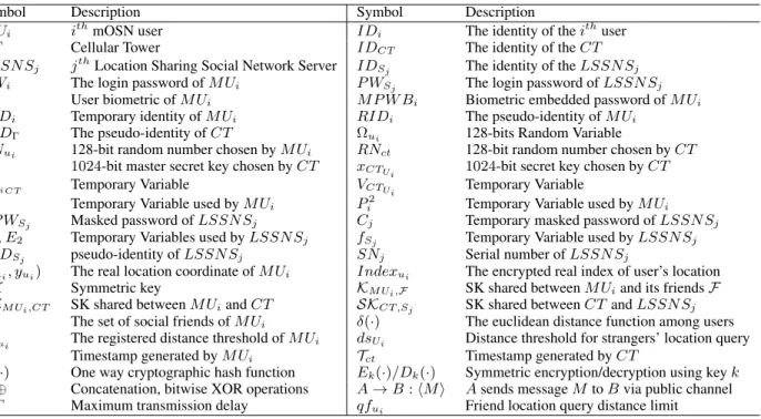
TABLE 1: Symbols and notations used in the proposed scheme.
Symbol Description Symbol Description
M Ui ithmOSN user IDi The identity of theithuser
CT Cellular Tower IDCT The identity of theCT
LSSN Sj jthLocation Sharing Social Network Server IDSj The identity of theLSSN Sj
P Wi The login password ofM Ui P WSj The login password ofLSSN Sj Bi User biometric ofM Ui M P W Bi Biometric embedded password ofM Ui
T IDi Temporary identity ofM Ui RIDi The pseudo-identity ofM Ui
RIDΓ The pseudo-identity ofCT Ωui 128-bits Random Variable
RNui 128-bit random number chosen byM Ui RNct 128-bit random number chosen byCT
XΓ 1024-bit master secret key chosen byCT xCTUi 1024-bit secret key chosen byCT
AUi CT Temporary Variable VCTUi Temporary Variable
Pi1 Temporary Variable used byM Ui Pi2 Temporary Variable used byM Ui
RP WSj Masked password ofLSSN Sj Cj Temporary masked password ofLSSN Sj
E1,E2 Temporary Variables used byLSSN Sj fSj Temporary Variable used byLSSN Sj
P IDSj pseudo-identity ofLSSN Sj SNj Serial number ofLSSN Sj
(xui, yui) The real location coordinate ofM Ui Indexui The encrypted real index of user’s location
SK Symmetric key KM Ui,F SK shared betweenM Uiand its friendsF
SKM Ui,CT SK shared betweenM UiandCT SKCT ,Sj SK shared betweenCTandLSSN Sj
Θ The set of social friends ofM Ui δ(·) The euclidean distance function among users
Dfui The registered distance threshold ofM Ui dsUi Distance threshold for strangers’ location query
Tui Timestamp generated byM Ui Tct Timestamp generated byCT
H(·) One way cryptographic hash function Ek(·)/Dk(·) Symmetric encryption/decryption using keyk
||,⊕ Concatenation, bitwise XOR operations A→B:hMi Asends messageM toBvia public channel
4T Maximum transmission delay qfui Friend location query distance limit
an open research problem to many popular OSNs. The CEO of Facebook has recently published an article “A Privacy-Focused Vision for Social Networking", which claims that the OSN giant is planning to implement end-to-end encryption on all its messaging services to increase privacy levels, and it has started experimenting with end-to-end encryption already [35]. The lack of privacy in OSNs leads to various security hazards like the identity theft, information leakage, and government impinge on user privacy [36]. However, the proposed scheme does not aim at providing complete end-to-end encryption on all messages between mobile user and the social media service provider.
The idea proposed in this paper serves three basic pur-poses. First, it provides centralized storage of location-based information and social information into single entity [34]. Second, it ensures secure communication of location sharing and update based messages, thus protecting them from vari-ous malicivari-ous attackers. Finally, for location sharing, it facil-itates a low computation and communication cost on mobile device, as it avoids encryption via public key infrastructure (PKI). These make the proposed scheme suitable for practical environments.
We find that existing centralized location sharing of the scheme suffer from the man-in-the-middle attack, replay at-tack, and DoS attack [37]. Our contribution is to secure location sharing and location query based messages and to protect them from adversary. We do not exploit direct key sharing between the user and the service provider. As shown in Figure 3,M Uigoes through a three-factor authentication process withCT, and establish the session key SKM Ui,CT
(= SKCT ,M Ui), shared with CT. All location-based
mes-sages between M Ui and CT are encrypted with this key. Similarly, Figure 4 shows how CT and LSSN S authen-ticate and establish their shared session key SKSj,CT(= SKCT ,Sj).
III. MATHEMATICAL FUNDAMENTALS
To describe our proposed scheme, we have applied the collision-resistant one-way hash function [38], Chebyshev polynomial [39], [40], biometrics and fuzzy extractor, bitwise XOR operator. In this section, we describe these fundamental concepts in brief.
A. THE COLLISION-RESISTANT ONE-WAY HASH FUNCTION
The input to a one-way cryptographic hash function H:
{0,1}∗ → {0,1}k is any string of 0 and 1. That is, s ∈
{0,1}∗. The output of the function is another binary string
H(s)∈ {0,1}kwhose length is fixedkbits. The property of collision-resistant ofH(·)is described in the following [41].
Definition 1. The advantage probability of any adversary
A’s to find any collision with the execution timetnis denoted and defined byAdvHASH
A (tn) =P r[(p, q)∈RA:p6=q and H(p) = H(q)], whereP r[M]is the probability of an event M and an adversaryAselects a random pair(p, q). By an
(, tn)-adversaryAattacks the collision resistance ofH(·), it specify that the computation time of Ais at mosttn and thatAdvHASH
A (tn)≤.
FIGURE 1: The architecture for location sharing in the mOSN through multiserver system.
B. THE CHEBYSHEV POLYNOMIAL: DEFINITION AND PROPERTIES
The Chebyshev polynomial Tn(x) : [−1,1] → [−1,1]of degreenis defined as [39]:
Tn(x) =
cos(n·arccos(x)) ifx∈[−1,1]
cos(nθ) ifx=cosθ, θ∈[0, π]. The Chebyshev polynomial can be expressed in terms of the following recurrecnce relation.
Tn(x) = 1 whenn is equal to0 x whenn is equal to1 whenn is greater 2xTn−1(x)−Tn−2(x) than or equal to2. Definition 2. The semi-group property of the enhanced Chebyshev polynomial holds on the interval(−∞,+∞)and is defined as follows [42].Tn(x) = 2xTn−1(x)−Tn−2(x) (mod p), wheren ≥ 2,x ∈ (−∞,+∞), andpis a large prime number. Here, Tr(Ts(x)) ≡ Trs(x) ≡ Ts(Tr(x))
(mod p), where Zp∗ = {a|0 < a < p,gcd(a, p) = 1} ={1,2, . . . , p−1}.
Definition 3. For any givenxandy, it is computationally infeasible to find an integer s such that Ts(x) = y. It is referred to as the Chaotic map-based discrete logarithm problem (CMDLP) [43]. The advantage probability ofAto solve CMDLP isAdvCM DLP
A (t2) =P r[A(x, y) =r :r ∈
Zp∗, y=Tr(x) (modp)].
C. THE BIOMETRICS AND FUZZY EXTRACTOR
For secure authentication, various authentication protocols use some biometrics features, such as iris and fingerprint as the key for their uniqueness property [44], [45]. Using the Fuzzy extractor technique, we can produce the identical output string, though the input biometric will differ from the stored biometric samples up to a given threshold limit for permissible error tolerance. The Fuzzy extractor is defined by two algorithms:Generate(·) andReproduce(·), which are deterministic and probabilistic.
Definition 4. Let us suppose that a biometric key of lengthn bits is generated from the biometricsB. We also consider that
R={0,1}kis a metric space of finite dimensional biometric data points. The following two functions are defined next.
• Generate: This function generates a pair(η, µ), where η ∈ {0,1}n represents the biometric key and µ is a public value which is used as a parameter by the Reproduce function for a given inputB ∈ R.
• Reproduce:This function regenerates the original bio-metric keyη =Reproduce(Bi, µ), whereη ∈ {0,1}n from the entered biometricsBi and original biometrics
BandBiare close in terms of some distance metric such as the Hamming distance. To be close, this distance must not to be more thanE.Eis a pre-defined threshold value. IV. THE ADVERSARY MODEL AND SYSTEM MODEL This section briefly describes the basic attack model or adversary model applicable for our proposed scheme. More-over, we depict the outline of the system model adopted for our proposed location sharing scheme for the online social network.
A. THE THREAT MODEL
We primarily assume that cellular tower (CT)is a trusted body and define the threat model concerning the location-sharing social network servers(LSSN Ss)and the user(U). We define the model below:
• Registered entities like U,LSSN S andCT commu-nicate through a public insecure wireless channel. The proposed scheme adopts the widely-accepted Dolev-Yao threat model (DY model) [46]. An attacker or a malicious user has all the capabilities of executing all potential attacks defined in the classical DY model.
• A registered or authorized user or a privileged insider of
the system may turn into a malicious user, who illegally intends to access various location or social information of other genuine users.
• LSSN Ss exhibit an ‘honest but curious’ nature. They alone, or after colluding with other servers, try to re-trieve the social network topology or location informa-tion of other registered users.
B. THE SYSTEM MODEL
Figure 1 shows the basic system model of the proposed scheme. Here, we define the basic entities, which are de-scribed as follows:
• Mobile user (U): Sends and responds to three types of request queries. These include sharing of location information to other social friends and strangers, up-dating own location information and querying a friend’s location information.
• Location Sharing Social Network Servers(LSSN S): Responsible for storing, updating and informing various location information ofU.
• Cellular Tower (CT): : It is a trusted entity, which receives, processes and forwards various messages ofU andLSSN S. All messages communicated betweenU andLSSN Sare communicated viaCT.
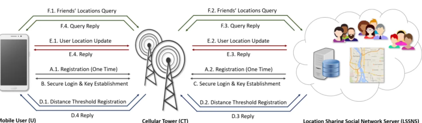
The overall flow of the model is shown in Figure1. First, the mobile user and the Location Sharing Social Network ServerLSSN Sjregister to a cellular towerCT (process A). This is a one-time operation and is executed through a secure channel. Next, the mobile user M Ui and LSSN Sj make a secure login to the registered CT and establish a shared session key (processes B and C respectively). Thereafter, the mobile user registers a distance threshold to LSSN Sj via CT, in which corresponding social friends can be searched (process D). When required, the mobile user updates his/her current location to LSSN Sj through the cellular tower (process E). Finally, the mobile user obtains his/her social friends’ identities and locations for those who are willing to share their information fromLSSN Sj through the cellular tower (process F).
In general, three major security challenges are primar-ily faced by location sharing schemes designed for mOSN applications. First, various location-based services must be privacy-preserving. An attacker or malicious user must not be able to access and/or modify personal information ofU. Sec-ond, to ensure user location privacy,LSSN S should store various fake or dummy identities of U. Finally, a physical distance threshold between U and friend or stranger of U must be registered. A location query about U’s friends or strangers are processed only if their current physical distance is within that predefined distance threshold.
V. THE PROPOSED SCHEME
In order to design the proposed scheme, various symbols are used. The symbols and notations are tabulated in Table1.
A. THE REGISTRATION PHASE
This phase involves two distinct registration processes, namely, (a) the registration of a mOSN user (M Ui) to a cellular tower, and (b) the registration of a LSSN Sj to a cellular tower. The registration process is a one-time opera-tion that is executed through a secure channel; the message communication for this phase is shown in Figure2.
FIGURE 2:Message Communication in Registration Phase. Please refer to SectionsV-A1andV-A2.
1) Mobile User Registration
In this phase, a series of steps are executed for the registration of a mobile userM Uito theCT. These steps are as follows.
Step UR1:
1) M Uiselects own identity, password, and biometrics as IDi,P Wi,Birespectively.
2) M Ui selects parametersnandλ, which are two128 -bit random numbers.
Step UR2:
1) M Ui uses the fuzzy extractor (·) function to pro-duce (ηi, µi) = Generation(Bi) and computes the biometric embedded passwordM P W Bi =H(IDi|| H(P Wi||ηi||n)).
2) Through a secure channel, M Ui delivers its registra-tion message{IDi, dfUi, dsUi,(M P W Bi⊕λ)}to the CT.
Note thatIDiandP Wiare randomized by concatenating
128-bit (16-byte) random numbers [43], [47], [48]. We mask the user id and password asM P W Bi =H(IDi||H(P Wi|| ηi||n)). Thus, guessing ofIDiandP WifromM P W Biis infeasible, as it is computationally hard to guess three secrets simultaneously. An 128-bit random number can generate
1038 possible values (as 2128 ≈ 1038). So, the guessing possibility is only≈ 1
1038[49], [47].
Step UR3:
1) CT randomly selects its own 1024-bit master secret keyXΓ.
2) For eachhCT ↔ M Uiipair, CT randomly selects a
1024-bit secret keyxCTUi.
3) CT computes AUi CT =H(H(IDi ⊕xCTUi) ||XΓ), VCTUi =AUi CT ⊕M P W Bi.
4) CT chooses its pseudo-identity as RIDΓ =
H(IDCT||XΓ). Step UR4:
1) CT provides an anonymous temporary identity for each mOSN user M Ui. This is done by selecting a random but temporary identity T IDi for each user M Ui.
2) CT savesmhCT ↔M Uiikey-plus-id combinations
{T IDi, (IDCT, VCTUi, RIDΓ) | 1 ≤ j ≤ m} in
mobile device ofM Ui.
Note that for all M Uis, the CT saves the record
{IDi, T IDi, xCTUi}in own database.
Step UR5:
1) M Ui computes Pi1 = H(P Wi|| ηi)⊕n and Pi2 = H(IDi||P Wi||ηi||n).
2) M UimodifiesVCTUi asVCT0 Ui =VCTUi ⊕λ,RIDi= T IDi⊕ H(IDi ||VCT0 Ui) and RID0Γ = RIDΓ ⊕
H(ηi||n)for all1≤j≤m.
3) M Ui stores parametershµi,Pi1,Pi2,VCT0 Uis,RIDis andRID0Γiand removesVCTUis,RIDΓ andT IDis
from own mobile device.
2) The Location Sharing Social Network Server Registration Phase
Each location sharing social network serverLSSN Sj regis-ters to the cellular towerCT through the following steps:
Step SR1:
1) LSSN Sj chooses own id and password asIDSj and P WSj.
2) It selects one random numberbof128-bit long.
Step SR2:
1) LSSN Sj computes masked password RP WSj = H(IDSj ||P WSj)andCj=H(IDSj ||P WSj ||b).
2) LSSN Sj submits hIDSj, Cji to CT via a secure
channel.
Step SR3:
1) CT uses its master secret key XΓ and one
ran-dom number r (128-bit) to compute Kj = H(H(IDSj||XΓ)⊕r), andE1 =Kj⊕Cj = Kj⊕ H(IDSj ||P WSj ||b).
2) CT embeds the parameters {E1, TXΓ(Kj)} in mem-ory of eachLSSN Sj.
3) CT saves pairhIDSj, SNj, riinto its database, where SNj is the identity or serial number of the server LSSN Sj.
Step SR4:
1) LSSN Sj computes E2 = RP WSj ⊕b andfSj = H(RP WSj||b).
2) LSSN SjstoresE2,fSj,H(·)into its own memory.
The Summary of registration process of M Ui and LSSN SjtoCT is shown in Figure3.
B. THE MOSN USER LOGIN, AUTHENTICATION AND KEY ESTABLISHMENT PHASE
The mOSN userM Uimakes a secure login to the registered CT and establishes a shared session key through the follow-ing steps:
Step ULA1:
1) M Ui inputs own identity, password, and biomerics (noisy) asIDi,P Wi, andB0
irespectively.
mOSN user(M Ui) Cellular tower(CT)
InputIDi,P WiandBi.
Select128-bit numbersnandλ. Compute(ηi, µi) =Generation(Bi),
M P W Bi=H(IDi||H(P Wi||ηi||n)).
{IDi,(M P W Bi⊕λ)}
−−−−−−−−−−−−−→
Securechannel Select own master secret keyXΓ.
SelectxCTUifor each{CT↔M Ui}pair. ComputeAUi CT=H(H(IDi⊕xCTUi)||XΓ),
VCTUi=AUi CT⊕M P W Bi,
RIDΓ=H(IDCT||XΓ).
Select temporary identityT IDifor eachM Ui.
For all{CT↔M Ui}pairs, store
{T IDi,(IDCT, VCTUi, RIDΓ)}in memory ofM Ui. Store record{IDi, T IDi, xCTUi}inCT. {M obile Device} ←−−−−−−−−−−− Securechannel ComputeP1 i=H(P Wi||ηi)⊕n, P2
i=H(IDi||P Wi||ηi||n),
V0 CTUi=VCTUi⊕λ Compute RIDi=T IDi⊕H(IDi||VCT0 Ui), RID0 Γ=RIDΓ⊕H(ηi||n). Store{µi,Pi1,Pi2,V 0 CTUis,RIDis, RID0
Γ}into own device memory. DeleteVCTUis,RIDΓandT IDis
fromM Uimobile device memory.
Location Sharing Social Network Cellular tower(CT)
Server(LSSN Sj)
Selects id, password asIDSjandP WSj and128-bit numberbrandomly.
RP WSj=H(IDSj||P WSj),
Cj=H(IDSj||P WSj||b).
hIDSj,Cji
−−−−−−−−−→ securechannel
Generate128-bit numberrrandomly. Using the master secret keyXΓ,
ComputesKj=H(H(IDSj||XΓ)⊕r),
TXΓ(Kj),E1=Kj⊕Cj.
servermemory{E1,TXΓ(Kj)}
←−−−−−−−−−−−−−−−−−−− securechannel
ComputesE2=RP WSj⊕b, StoreshIDSj, SNj, riinto own database.
fSj=H(RP WSj||b). StoreE2,fSj,H(·),
into server memory.
FIGURE 3: The Registration phases ofM UiandLSSN Sjin the proposed scheme
2) Using stored µi and Pi1, M Ui computes ηi = Reproduction(B0
i, µi) and generates n0 = Pi1⊕ H(P Wi||ηi).
3) M UicalculatesH(IDi||P Wi||n0||ηi)and compares with storedP2
i.
4) If the verification succeeds, go toStep ULA2, else,exit.
Step ULA2:
1) M Uirandomly generatesΩui(128-bit number).
2) Using stored paratemerVCT0
Ui,M Uicomputes : a) M P W Bi=H(IDi||H(P Wi||n0||ηi)). b) AUi CT =V 0 CTUi⊕M P W Bi. c) M1=AUi CT⊕Ωui⊕ Tui⊕H(IDCT). d) T IDi=RIDi⊕H(IDi||VCT0 Ui). e) T IDi∗=T IDi⊕H(IDCT|| Tui)
3) M Ui uses the current login timestampTui and
com-putes a hash valueH1=H(IDi|| M1||Ωui|| Tui).
4) Through a public channel, M Ui sends{T ID∗i,M1,
H1,Tui}toCT. Step ULA3:
1) CT verifies if|T∗
ui− Tui|
?
≤ 4T. If verification holds go to step2, elseexit.
2) CT calculatesT IDi =T ID∗i⊕H(IDCT ||Tui).
3) Corresponding to calculated T IDi, CT finds the recordh{IDi, xCTUi}ifrom own database.
4) CT computesBCTUi =H(H(IDi⊕xCTUi)||XΓ).
5) CT computesP1=M1⊕ Tui⊕H(IDCT)⊕BCTUi
=Ωui.
Note thatCT obtainesP1of step(5), asAUi CT =BCTUi
=H(H(IDi⊕xCTUi)||XΓ). Step ULA4:
1) CT uses received parameters to prepares a hash value H2=H(IDi||M1||P1||Tui).
2) CTverifies ifH2 ?
=H1. If verification holds go to step 3, elseexit.
3) CT saves the recordhIDi,Ωui,Tuiiin its database.
4) CT generates a128-bit random numberΩct.
5) CT computesM2 =BCTUi⊕Ωct⊕ Tct⊕IDi. Here
Tctis the current timestamp ofCT.
6) CT computes shared session key SKCT ,M Ui = H(IDi||IDCT ||BCTUi ||P1||Ωct||Tui||Tct).
7) CT prepares hash valueH3=H(IDi||P1||Ωct||Tui ||Tct||SKCT ,M Ui).
8) Through public channel,CT sends authentication re-sponse message{M2, H3,Tct}toM Ui.
Step ULA5:
1) M Ui receives an authentication response message from step8ofU LA4.
2) M Ui verifies the transmission delay by comparing received and current timestamps. Go to step3, if veri-fication holds, elseexit.
3) M UicomputesP2=M2⊕Tct⊕IDi⊕AUi CT = Ωct.
Note that we obtainP2 of step(3), asAUi CT = BCTUi
=H(H(IDi⊕xCTUi)||XΓ). Step ULA6
1) M Ui generates a session key (mutually shared with CT) asSKM Ui,CT =H(IDi||IDCT ||AUi CT ||Ωui ||P2||Tui||Tct).
2) M Ui computes final hash value H4 =H(IDi ||Ωui ||P2||Tui||Tct||SKM Ui,CT).
3) IfH4 ?
=H3, thenM Uiconfirms that the session key SKM Ui,CT (= SKCT ,M Ui)is mutually verified and
established. Else,M Ui discards the session key and terminates the process.
For all message communicaions in the current session, M UiandCT use this key for message encryption.
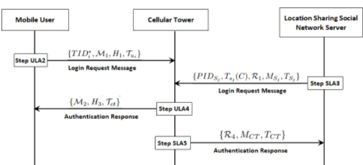
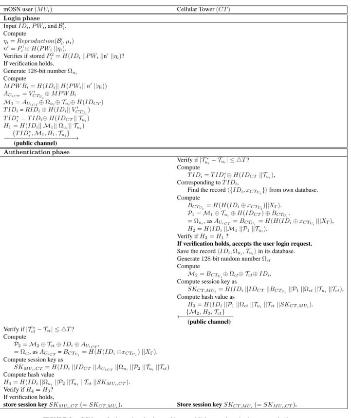
The Summary of mOSN user login, authentication and key establishment phase withCT is shown in Figure5 and the message communications of Login, Authentication and Key Establishment Phase is shown in Figure4.
FIGURE 4:Message Communication in Login, Authentication and Key Establishment Phase. Please refer to SectionsV-BandV-C.
C. THELSSN SJLOGIN, AUTHENTICATION AND KEY
ESTABLISHMENT PHASE
TheLSSN Sjmakes a secure login to the registered cellular towerCT and establishes a shared session key through the following steps:
Step SLA1:
1) LSSN Sjinputs own idIDSj and passwordP WSj.
2) LSSN Sj generatesRP W1 = H(IDSj||P WSj)and b1=E2⊕P W B1.
3) LSSN Sjuses generatedb1and computesfS0j =H(RP W1 ||b1).
4) LSSN Sj verifies iffSj
? = fS0
j. If verification holds,
go to stepSLA2, elseexit.
Step SLA2:
1) LSSN SjcomputesC=E1⊕H(IDSj||P WSj ||b1).
2) LSSN Sjgenerates random numbersj. 3) LSSN SjcomputesTsj(C).
4) LSSN SjcomputesK1=Tsj(TXΓ(C)). Step SLA3:
1) LSSN Sjgenerates128-bit random numberΩsj.
2) LSSN Sj computes R1 = C⊕Ωsj⊕Tsj(C)⊕TSj.
Here,TSj is the current timestamp ofLSSN Sj.
3) LSSN Sj generates its pseudo identity P IDSj = IDSj ⊕H(K1).
4) LSSN SjcomputesMSj =H(IDSj||C||K1||Ωsj|| TSj)
5) Finally, through a public channel,LSSN Sj sends its login request{P IDSj,Tsj(C),R1,MSj,TSj}to the
cellular towerCT.
Step SLA4:
1) CT receives login message and verifies if|T∗
Sj−TSj|
?
≤ 4T. If verification holds go to step2, elseexit. Here, TS∗
j is the current timestamp.
2) CT calculatesK10 =TXΓ(Tsj(C)). 3) CT calculates ID0S j = P IDSj ⊕H(K 0 1) = IDSj ⊕H(K1)⊕H(K10) =IDSj. 4) CT verifies if K10 ? = K1. If verification holds, CT
ensures thatID0Sj =IDSj and go to step5.
mOSN user(M Ui) Cellular Tower(CT) Login phase InputIDi,P Wi, andBi0. Compute ηi=Reproduction(Bi0, µi) n0=P1 i⊕H(P Wi||ηi). Verifies if storedP2 i =H(IDi||P Wi||n’||ηi)? If verification holds, Generate128-bit numberΩui
Compute M P W Bi=H(IDi||H(P Wi||n0||ηi)) AUi CT =V 0 CTUi⊕M P W Bi M1=AUi CT⊕Ωui⊕ Tui⊕H(IDCT) T IDi=RIDi⊕H(IDi||VCT0 Ui) T ID∗i=T IDi⊕H(IDCT|| Tui) H1=H(IDi|| M1||Ωui|| Tui) {T ID∗ i,M1, H1,Tui} −−−−−−−−−−−−−−−−−−−−→ (public channel) Authentication phase Verify if|T∗ ui− Tui| ≤ 4T? Compute T IDi=T ID∗i⊕H(IDCT||Tui), Corresponding toT IDi,
Find the recordh{IDi, xCTUi}ifrom own database.
Compute BCTUi =H(H(IDi⊕xCTUi)||XΓ). P1=M1⊕ Tui⊕H(IDCT)⊕BCTUi. = Ωui,asAUi CT =BCTUi =H(H(IDi⊕xCTUi)||XΓ), H2=H(IDi||M1||P1||Tui). Verify ifH2=H1?
If verification holds, accepts the user login request. Save the recordhIDi,Ωui,Tuiiin its database.
Generate128-bit random numberΩct
Compute
M2=BCTUi⊕Ωct⊕ Tct⊕IDi,
Compute session key as
SKCT ,M Ui=H(IDi||IDCT||BCTUi ||P1||Ωct||Tui||Tct),
Compute hash value as
H3=H(IDi||P1||Ωct||Tui||Tct||SKCT ,M Ui). {M2, H3,Tct} ←−−−−−−−−−−−−−−− (public channel) Verify if|T∗ ct− Tct| ≤ 4T? Compute P2=M2⊕ Tct⊕IDi⊕AUi CT, = Ωct, asAUi CT =BCTUi=H(H(IDi⊕xCTUi)||XΓ).
Compute session key as
SKM Ui,CT=H(IDi||IDCT||AUi CT ||Ωui||P2||Tui||Tct)
Compute hash value
H4=H(IDi||Ωui||P2||Tui||Tct||SKM Ui,CT).
Verify ifH4=H3?
If verification holds,
store session keySKM Ui,CT(=SKCT ,M Ui). Store session keySKCT ,M Ui(=SKM Ui,CT).
FIGURE 5: mOSN user login, authentication and key establishment phase in the proposed scheme.
5) CT finds the recordhIDSj, SNj, riin the database.
6) CT further computesC0=H(H(IDS0 j||XΓ)⊕r). 7) CT computes R2 = R1⊕ TSj⊕ C 0⊕ T sj(C) = H(H(IDSj ||XΓ)⊕r)⊕Ωsj ⊕TSj ⊕Tsj(C))⊕TSj ⊕H(H(IDSj ||XΓ)⊕r)⊕Tsj(C) = Ωsj.
8) CT uses the received parameters TSj and calculates
R3=H(ID0Sj||C 0||K0 1||R2||TSj). 9) CT verifies whetherR3 ? =R2.
10) On successful verification, CT accepts the login re-quest and considers the Location ServerLSSN Sj as authentic. Otherwise, CT terminates the session and
exit.
Step SLA5:
1) CT selects a128-bit random numberΩCT.
2) CT computesR4 =C0⊕ΩCT⊕TCT =H(H(IDSj ||XΓ) ⊕r) ⊕ΩCT ⊕TCT. Here, TCT is the current timestamp ofCT.
3) CT computes the mutually shared session key SKCT ,Sj =H(C
0||K0
1||TSj||TCT|| R2||ΩCT).
4) CT computes MCT = H(IDSj|| SKCT ,Sj|| R2||
ΩCT||TSj||TCT).
5) Through a public channel,CT sends the authentication response message{R4, MCT, TCT}toLSSN Sj.
Step SLA6:
1) LSSN Sj receives the authentication response mes-sage fromCT.
2) LSSN Sj verifies the transmission delay |TCT∗ − TCT|
?
≤ 4T, whereTCT∗ is the current timestamp. If verification holds, go to step3, elseexit.
3) LSSN Sj computes R5 = C0⊕ R4⊕ TCT = H(H(ID0S
j ||XΓ) ⊕r) ⊕H(H(IDSj ||XΓ) ⊕r) ⊕ΩCT ⊕TCT ⊕TCT = ΩCT.
Step SLA7:
1) LSSN Sj generates the session key mutually shared withCT asSKSj,CT =H(C||K1||TSj ||TCT ||ΩCT ||R5). 2) LSSN SjverifiesMCT ? =H(IDSj||SKSj,CT ||ΩCT ||R5||TSj ||TCT).
3) If verification succeeds, LSSN Sj confirms that the cellular towerCT is authentic and the current session keySKSj,CT (= SKCT ,Sj)is mutually verified and
established. Otherwise, discard the session key and exit.
The summary of the LSSN Sj login, authentication and key establishment phase is shown in Figure6.
D. THE DISTANCE THRESHOLD REGISTRATION PHASE
Every registered mOSN user M Ui needs to register a dis-tance threshold toLSSN Sj in which corresponding social friends can be searched and the message communications of Distance Threshold Registration Phase is shown in Figure7.
Step DR1:
1) M Uidecides a distance thresholdDfui beyond which M Ui does not allow his/her social friends to find himself in a friends’ location query.
2) M Ui sends encrypted distance registration message M sg1
dreg=hESKM Ui,CT(IDi|| Dfui||RNui||T Sui|| Rf lag = 1),H(IDi||RNui||T Sui),T Suii.
Here,RNui,T Sui,H(·)andE(·)convey their meaning
as tabulated in Table1.Rf lag= 1indicates that this message in intended for the distance threshold registration.
Location Sharing Social Network Cellular tower Server(LSSN Sj) (CT) Login phase InputIDSjandP WSj Compute RP W1=H(IDSj||P WSj) b1=E2⊕P W B1 Verifies if storedfSj=H(RP W1||b1)? If verification holds,
Generate128-bit numbersjandΩsj
Compute C=E1⊕H(IDSj||P WSj||b1) K1=Tsj(TXΓ(C)) R1=C⊕Ωsj⊕Tsj(C)⊕TSj Generate pseudo-identity P IDSj=IDSj⊕H(K1) Compute MSj=H(IDSj||C||K1||Ωsj||TSj) {P IDSj, Tsj(C),R1, MSj, TSj} −−−−−−−−−−−−−−−−−−−−−−−−−−−−→ (public channel) Authentication phase Verify if|T∗ Sj−TSj| ≤ 4T? Compute K0 1=TXΓ(Tsj(C)), ID0 Sj=P IDSj⊕H(K01) =IDSj, Corresponding toIDSj,
Find the recordhIDSj, SNj, rifrom own database.
Compute C0=H(H(ID0 Sj||XΓ)⊕r). R2=R1⊕TSj⊕C0⊕Tsj(C), =H(H(IDSj||XΓ)⊕r)⊕Ωsj⊕TSj⊕Tsj(C)) ⊕TSj⊕H(H(IDSj||XΓ)⊕r)⊕Tsj(C), = Ωsj,
Using receivedTSj, Compute
R3=H(ID0Sj||C 0||K0 1||R2||TSj) Verify ifR3 ? =R2 If verification holds,
CTaccepts the login request.
Generate128-bit random numberΩCT
Compute
R4=C0⊕ΩCT⊕TCT, =H(H(IDSj||XΓ)⊕r)⊕ΩCT⊕TCT
Compute session key as
SKCT ,Sj=H(C0||K10||TSj||TCT|| R2||ΩCT),
Compute hash valueMCTas
MCT=H(IDSj||SKCT ,Sj|| R2||ΩCT||TSj||TCT). {R4, MCT, TCT} ←−−−−−−−−−−−−−−−−− (public channel) Verify if|T∗ CT−TCT| ≤ 4T? Compute R5=C0⊕ R 4⊕TCT =H(H(ID0 Sj||XΓ)⊕r)⊕H(H(IDSj||XΓ)⊕r) ⊕ΩCT⊕TCT⊕TCT = ΩCT, Compute session key as
SKSj,CT=H(C||K1||TSj||TCT||ΩCT||R5)
Compute and verify hash value
MCT=?H(IDSj||SKSj,CT||ΩCT||R5||TSj||T S2). If verification holds,
store session keySKSj,CT(=SKCT ,Sj) Store session keySKCT ,Sj(=SKSj,CT).
FIGURE 6: TheLSSN Sjlogin, authentication and key establish-ment phases of the proposed scheme
FIGURE 7:Message Communication in Distance Threshold Regis-tration Phase refer to SectionV-D.
Step DR2:
1) CT uses session key SKCT ,M Ui and decrypts DSKCT ,M Ui(M sg1dreg).
2) CT verifies if|T Su∗i −T Sui|
?
≤ 4T, whereT Su∗i is the current timestamp. If verification holds, go to step
3, else terminate andexit.
3) CT computes the hash valueH(IDi||RNui||T Sui).
If the computed and received hash values are same, then go to step4, else discards the message andexit. 4) CT logs in to LSSN Sj and establishes the shared
session keySKCT ,Sj as explained in subsectionV-C.
5) CT encrypts and sends the distance registration mes-sage as M sg2
dreg = hESKCT ,Sj(IDi|| Dfui|| RNui|| RNct|| T Sct|| Rf lag = 1),H(IDi|| RNct|| T Sct), T SctitoLSSN Sj.
Step DR3:
1) LSSN Sj decrypts M sgdreg2 using the session key
SKSj,CT.
2) LSSN Sj verifies communication delay using the re-ceived and current timestamp values.
3) LSSN Sj verifies message integrity and authenticity by computing and comparing hash values with de-crypted parameters.
4) If verifications of steps(2)and(3)are successful, go to Step5, else terminate the session andexit.
5) LSSN Sj saves record {IDi,Dfui} and sends re-sponse messageM sg1
resp = ESKCT ,Sj(IDi ||RNui ||RNct||‘ok0)toCT.
Step DR4:
1) CT decryptsM sg1respusing the shared session key. 2) CT verifies the received random number RNct and
sends M sgresp2 = ESKCT ,M Ui(IDi||RNui||‘ok
0) to
M Ui.
3) M Uidecrypts the messageM sg2respusing the shared session keySKM Ui,CT
4) M Ui verifies the random numberRNui. If these
ver-ification holds, go to step 5.Otherwise, termiate the session andexit.
5) M Ui reads ‘ok0 message and distance registration process successfully terminates.
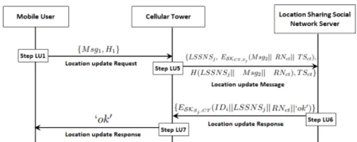
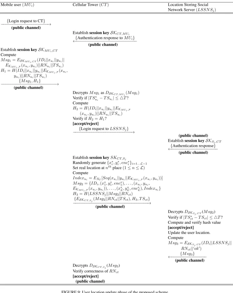
E. THE USER LOCATION UPDATE PHASE
In this subsection, we describe how mOSN userM Uiupdates his current location to the Location Sharing Social Network ServerLSSN Sj and the message communications of User Location Update Phase is shown in Figure8. The location updation is done through the cellular towerCT, following the steps as mentioned in subsectionV-B,M Uimakes a secure login toCT and mutually estabsishes a shared session key
SKM Ui,CT(= SKCT ,M Ui). Next, it executes the following
steps:
Step LU1:
1) M Uiselects a one-time128-bit random numberRNui.
2) M Uiuses the shared session keySKM Ui,CTand sends
an encrypted message M sg1 = ESKM Ui,CT(IDi|| xui||yui||EKM Ui,F(xui, yui)||RNui||T Sui)toCT.
3) M Ui sends a hash valueH1 = H(IDi|| xui|| yui|| EKM Ui,F(xui, yui)||RNui||T Sui)toCT.
FIGURE 8: Message Communication in User Location Update Phase. Please refer to SectionV-E.
Note that, (xui, yui)is the current location ofM Ui, and EKM Ui,F(xui, yui)is the current location ofM Uiencrypted
with the symmetric key{KM Ui,F}, mutually shared between M Uiand all trusted friendF.
Step LU2:
1) CT receives location update message {M sg1, H1}
fromM Ui.
2) CT uses SKCT ,M Ui and decrypts M sg1 as DSKCT ,M Ui(M sg1).
3) CTretrieves parametersIDi,(xui, yui),EKM Ui,F(xui, yui),RNuiandT Suirespectively (from step2).
4) CT verifies if|T Su∗i −T Sui|
?
≤ 4T, whereT Su∗i is the current timestamp. If the verification holds then go to step LU3, else discards the received message and exit.
Step LU3:
1) CT uses the decrypted parameter and computes a hash valueH2 =H(IDi||xui||yui||EKM Ui,F(xui, yui)|| RNui||T Sui).
2) CT verifies ifH2 ?
=H1. If the verification holds then
go to step3, else terminate the session andexit. 3) CT confirms the authenticity and integrity of the
mes-sage and makes a login toLSSN Sj.
4) CT andLSSN Sj establishes a mutually shared ses-sion keySKCT ,Sj as mentioned in subsectionV-C. Step LU4:
1) CT generates L − 1 dummy locations and L − 1 dummy encrypted string chosen randomly as
{x∗i, y∗i, enc∗i}i=1...L−1.
2) CT randomly put M Ui’s real updated location in-formation string at thenth place among the dummy information set,(1≤n≤ L).
3) The sequence number of M Ui’s real location update information is encrypted byCT with its own master secret keyXΓ, i.e.,Indexui =EXΓ[Sequence(xui|| yui||EKM Ui,F(xui, yui))].
Mobile user(M Ui) Cellular Tower(CT) Location Storing Social Network Server(LSSN Sj)
{Login request to CT} −−−−−−−−−−−−−−−−−−−−→
(public channel)
Establishsession keySKCT ,M Ui {Authentication response toM Ui}
←−−−−−−−−−−−−−−−−−−−−−−−−−− (public channel)
Establishsession keySKM Ui,CT
Compute M sg1=ESKM Ui,CT(IDi||xui||yui|| EKM Ui,F(xui, yui)||RNui||T Sui) H1=H(IDi||xui||yui||EKM Ui,F(xui, yui)||RNui||T Sui) {M sg1, H1} −−−−−−−−−−−−−−−−−−−−−−−→ (public channel) DecryptsM sg1asDSKCT ,M Ui(M sg1) Verify if|T Su∗i−T Sui| ≤ 4T? Compute H2=H(IDi||xui||yui||EKM Ui,F (xui, yui)||RNui||T Sui) Verify ifH2=H1? [accept/reject] {Login request toLSSN Sj} −−−−−−−−−−−−−−−−−−−−−−−−−→ (public channel)
Establishsession keySKSj,CT {Authentication response} ←−−−−−−−−−−−−−−−−−−−−
(public channel)
Establishsession keySKCT ,Sj
Randomly generate{x∗i, yi∗, enc∗i}i=1...L−1
Set real location atnthplace(1≤n≤ L) Compute
Indexui=EXΓ[Seq(xui||yui||EKM Ui,F(xui, yui))]
M sg2={IDi,(x∗1, y∗1, enc∗1), . . . ,(xui, yui, EKM Ui,F(xui, yui)), . . . ,(x ∗ L, y∗L, enc∗L), Indexui} H3=H(LSSN Sj||M sg2||RNct) {ESKCT ,Sj(M sg2||RNct||T Sct), H3, T Sct} −−−−−−−−−−−−−−−−−−−−−−−−−−−−−−−−→ (public channel) DecryptsDSKSj ,CT(M sg2) Verify if|T S∗ ct−T Sct| ≤ 4T? Compute and verify hash value
[accept/reject]
Update the user location. Compute M sg3=ESKSj ,CT(IDi||LSSN Sj|| RNct||‘ok0) {M sg3} ←−−−−−−−−−−−−−−− (public channel) DecryptsDSKCT ,Sj(M sg3) Verify correctness ofRNct [accept/reject] (public channel)
FIGURE 9: User location update phase of the proposed scheme
1) CT prepares the message M sg2 = {IDi, (x∗1, y1∗, enc∗1), . . . ,(xui, yui, EKM Ui,F(xui, yui)), . . . ,(x
∗ L,
y∗L, enc∗L), Indexui}.
2) CT generates a128-bit random numberRNct. 3) sends {LSSN Sj, ESKCT ,Sj(M sg2|| RNct|| T Sct),
H(LSSN Sj|| M sg2|| RNct), T Sct} to server LSSN Sj.
Step LU6:
1) LSSN Sj uses its session keySKSj,CT (shared with CT) and decrypts the messageM sg2, random number
RNct, and timestampT Sct.
2) LSSN Sj checks the transmission delay using the re-ceived and current timestamps.
3) LSSN Sjchecks message integrity by checking com-puting a fresh hash value from the decrypted parame-ters.
4) LSSN Sjupdates the user location and sendsM sg3=
ESKSj ,CT(IDi||LSSN Sj||RNct||‘ok0)toCT.
Step LU7:
1) CTuses the session keySKCT ,Sjand decryptsM sg3.
2) CT verifies the correctness ofRNct. If it is correct, go to step3, else terminate the session andexit.
3) CT forwards‘ok0toM Ui.
The user location update phase is summarized in Figure9.
Remark 2. When the user reaches a new place, he/she updates his/her location in theLSSN S’s database to ensure thatLSSN Sknows the user’s real-time location.M Ui exe-cutes the user location update phase and sends the current lo-cation coordinate(xui, yui)(obtained by GPS) toLSSN S.
As the user location update phase of our proposed scheme is based only on the private key encryption, cryptographic hash function and xor operation, it is both secure and lightweight. Table 4 reveals that considering all the entities, this location update process takes only 0.0721 second. Hence, LSSN S can update the current location ofM Uivery quickly.
Depending on the population density, potential users, etc., the LTE technology nowadays requires cellular towers (or BTSs) to be spaced in the range of 2km to 5km [50]. When the mOSN user M Ui moves to a new cellular tower zone, he/she needs to register to CT. Once the registration is complete,M Uiprovides his/her location update toLSSN S and access other location-based services fromLSSN S. This mobile user registration process is a one-time task and incurs very small computation cost on a mobile device. As presented in Figure 2 and Table 3,M Uiregistration has the computa-tion cost of 5*TH + 5*TX +TF E, which essentially takes only 0.0656 second. This evidences that the user registration process is very efficient.
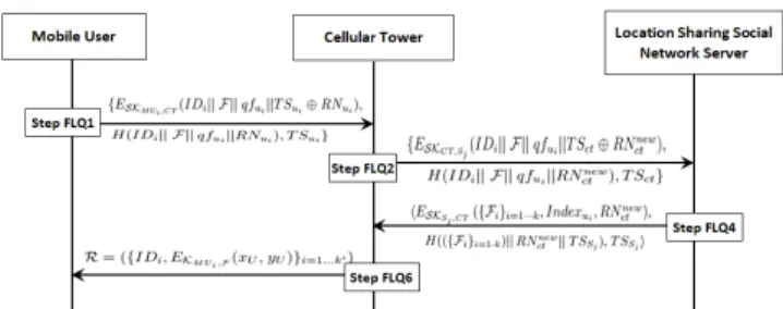
F. THE FRIENDS’ LOCATIONS QUERY PHASE
In this subsection, we describe how M Ui achieves his/her social friends’ identity and location, who are willing to share their information. The message communications of Friends’ Locations Query Phase is shown in Figure10.
FIGURE 10:The Message Communication in Friends’ Locations Query Phase. Please refer to SectionV-F.
Step FLQ1:
1) M Uimakes a secure login toCT and mutually estab-lishes a shared session keySKM Ui,CT(=SKCT ,M Ui)
(As explained in subsectionV-B).
2) M Ui sends {ESKM Ui,CT(IDi|| F || qfui||T Sui ⊕ RNui), H(IDi|| F ||qfui||RNui), T Sui}toCT.
Note that the message F is a request to find ‘friends’. T Sui, RNui, E(·) and H(·) convey their usual meanings
as explained in Table1.
Step FLQ2:
1) CT receives request fromM Ui, and checks if|T Su∗i−
T Sui|
?
≤ 4T. Here,T S∗uiis the current timestamp. If
the verification holds, go to step2, elseexit.
2) CTuses its session keySKCT ,M Ui(shared withM Ui)
to decrypt the encrypted user message.
3) CT uses received timestamp T Sui and parameter T Sui ⊕RNui to retrieve the random number as RNu0
i =T Sui⊕RNui⊕T Sui.
4) CT computes hash value H3 = H(IDi|| F || qfui||RN
0
ui). If the computed H3 and the received
hash value does not match, thenCT rejects the request immediately. Otherwise, go to step5.
5) CT logs in to the serverLSSN Sjand creates a shared session keySKCT ,Sj, as explained in subsectionV-C.
6) Through a public channel,CTforwards{ESKCT ,Sj(IDi
||F || qfui||T Sct ⊕ RN new ct ), H(IDi|| F || qfui|| RNnew ct ), T Sct}toLSSN Sj. Step FLQ3:
1) LSSN Sjreceives the message fromCT and decrypts the message using its session key SKSj,CT (shared
withCT).
2) LSSN Sj checks the communication delay using cur-rent timestampT Sct∗ and the received timestampT Sct. if verification holds, go to step 3, else terminate the session andexit.
3) LSSN Sj retrieves RNctnew and computes fresh hash value with the decrypted parameter and compares with the received hash value.
4) If verification holds, go to stepFLQ4, else terminate the session andexit.
Step FLQ4:
1) LSSN Sj finds the setΘcontaining a database entry for all friends ofM Ui.
2) LSSN Sj finds whether δ((xp, yp),(xuit, yuit)) ≤ min(qfui, dfs)s∈Θ, p = 1,· · ·, k,andt = 1,· · · , k,
where δ(·) is the distance function and (xuit, yuit) are one real andk−1 fake locations ofM Ui. Here, database entry ofIDiis excluded.
3) For all friends α ∈ Θ, LSSN Sj includes record (α,(p, enc∗p),Indexα) in the result set if the coordi-nate(xαit, yαit)meets the distance requirement. 4) Corresponding to k coordinate entries of M Ui
(xui, yui)i=1···k, LSSN Sj prepares k subsets {Fi}i=1···kand adds them to result set.
5) LSSN Sj usesRNctnew (the random number sent by CT),T SSj (the current timestamp) and encrypts the
result set using the shared session keySKSj,CT.
6) Through public channel, LSSN Sj forwards mes-sage hESKSj ,CT ({Fi}i=1···k, Indexui, RN
new ct ), H(({Fi}i=1···k)||RNctnew||T SSj),T SSjitoCT. Step FLQ5:
1) CT receives the encrypted result set fromLSSN Sj. 2) CT decrypts it using own shared session keySKCT ,Sj
to obtain{Fi}i=1···k,Indexui, andRN
new ct .
3) CT verifies transmission delay by comparing the current timestampT S∗
Sj and the received timestamp T SSj.
4) CT verifies the value of receivedRNnew
ct with stored RNnew
ct .
5) If both verification of step3and4is successful, then go to stepF LQ6, elseexit.
Step FLQ6:
1) CT decrypts Indexui as DXΓ(Indexui) = DXΓ
(EXΓ(Seq(xui|| yui|| EKM Ui,F(xui, yui)))) and
re-trieves the real sequence numberγ.CT uses its master secret key for the decryption.
2) CT discurds all records{Fi}i6=γ and accepts onlyFγ. 3) CT finds every present userUin the datasetFγ. 4) CT decrypts IndexU and finds its real center point
locationγU.
5) CTretrievesencγU =EKM Ui,F(xU, yU)and prepares
answer setR.
6) CT sends the friend set R= ({IDUi, EKM Ui,F(xU,
yU)}i=1...k0)toM Ui.
Remark 3. The existing location sharing schemes for OSN suffer from multiple security drawbacks. The purpose of our research is to design a secure and efficient location sharing scheme for OSN. User location updates and friend’s location queries are two essential operations for location sharing services. As mentioned in existing location sharing schemes [28], [29], [34], group key-establishment among a
user and its trusted social friends is an intrinsic require-ments. In the literature, several group key distribution and key-establishment schemes among social friends have been proposed in distributed online social networks [51], [52], [53], [54].
Unlike those schemes, our proposed one is not designed for purpose group key distribution and key-establishment among social friends. That said, the key-establishment pro-cess among social friends advocated by Y. Jung et al. [51] and L. Guo et al. [54] can be adapted to work with our proposed scheme.
VI. SECURITY ANALYSIS
In this section, we provide the detail security analysis of the proposed scheme. This is done in two ways. First, we present the authentication proof Using Burrows-Abadi-Needham (BAN) logic. Second, we present an informal secu-rity analysis to logically explain how and why the proposed scheme resists various security attacks.
A. AUTHENTICATION PROOF USING BAN LOGIC
BAN logic is used to analyze the security of any authen-tication scheme to verify the secure transmission between two communicating parties of that network [55]. In this section, we use BAN logic to show that the proposed scheme actually achieves the authentication goals. The basic syntax and semantics of BAN logic are explained in Table2.
TABLE 2: Notations and their descriptions used in BAN logic Symbol Description
Q|≡S Qbelieves that the statementSis true QCS Qcan see the statementS
#(S) FormulaSis considered as fresh Q|vS Qsaid the statementSonce
Q⇒S Qkeeps jurisdiction over the statementS
hSiT FormulaSis combined with the formulaT Q←→K R OnlyQandRknow the value of the keyKand
it is used for communication between them QS R OnlyQandRknow the secret statementS.
Principals trusted byQ&Rmay knowS SK Current session key
The main logical postulates of the BAN logic are defined by a set of laws or rules as listed below [55], [56].
• Law 1 (Message Meaning Law (MML)).
Q|≡RKQ,QChSiK
Q|≡R|vS .
• Law 2 (Nonce Verification Law (NVL)). Q|≡#(S),Q|≡R|vS
Q|≡R|≡S .
• Law 3 (Freshness Conjuncatenation Law (FCL)). Q|≡#(S)
Q|≡#(S,T).
• Law 4 (Jurisdiction Law (JL)). Q|≡R⇒S,Q|≡R|≡S
Q|≡S .
• Law 5 (Additional Laws (AL)). Q|≡(S,T) Q|≡S , QC(S,T) QCS , Q|≡Rv(S,T) Q|≡RvS . 14 VOLUME 4, 2016
In order to show that the proposed scheme ensures authen-tication, two goals, as mentioned in the following, must be achieved. Goal 1.M Ui|≡(M Ui SK ←→CT). Goal 2.CT |≡(M Ui SK ←→CT).
In the proposed scheme, there will be two basic types of messages as follows:
Message 1. M Ui → CT: { T IDi∗, H(H(IDi ⊕ xCTui||xΓ))⊕Ωui⊕ Tui⊕H(IDCT),Tui,H1}.
Message 2.CT →M Ui: {BCTUi⊕Ωct⊕ Tct⊕IDi,Tct, H3}.
The above generic messages have to be converted to ideal-ized messages. These idealideal-ized messages are as follows.
Message 1.M Ui→CT:{T IDi,Tui,hIDi,xCTUi,Ωui, Tui,H(IDCT)ixΓ,H1}.
Message 2.CT →A:{Tct,hΩctTct,IDi,ixΓ,H3}.
With the following assumptions, the authentication proof of our proposed scheme is presented as follows:
A.1:M Ui |≡#(Tct); A.2:CT |≡#(Tui); A.3:M Ui |≡(M Ui AuiCT CT); A.4:CT |≡(M Ui AuiCT CT); A.5:M Ui |≡CT ⇒(IDct,Ωct,Tct); A.6:CT |≡M Ui⇒(IDi,Ωui,Tui); A.7:M Ui |≡Tui; A.8:M Ui |≡Ωui; A.9:M Ui |≡IDi; A.10:M Ui|≡IDCT; A.11:CT |≡Tct; A.12:CT |≡Ωct; A.13:CT |≡IDCT.
Next, we shall show that two goals mentioned earlier can be achieved using the assumptions, idealized messages and Basic BAN logic laws.
From the first message, we may obtain the following.
• S1: CT C {IDi, Tui, hIDi, xCTui, Ωui, Tui, H(IDCT)ixΓ,H1}.
• S2: Using AL, we derive: CT C hIDi, xCTui, Ωui, Tui, H(IDCT)ixΓ.
• S3: According to A.4 and MML, we obtain, CT |≡
M Ui|v(IDi,xCTui,Ωui,Tui, H(IDCT)).
• S4: According to A.2 and FCL, we get,CT |≡#(IDi,
xCTui,Ωui,Tui, H(IDCT)).
• S5: According to NVL, we have,CT |≡M Ui|≡(IDi, xCTui,Ωui,Tui, H(IDCT)).
• S6: Using A.6 and JL, we get, CT |≡ (IDi, xCTui,
Ωui,Tui, H(IDCT)).
• S7: FromS6 and AL, we obtain,CT |≡ Ωui,CT |≡ Tui,CT |≡IDi.
• S8: According to A.11, A.12, A.13, we get, CT |≡
IDCT,CT |≡ TctandCT |≡Ωct.
• S9: Since SKCT ,M Ui = H(IDi ||IDCT ||BCTui|| P1||Ωct ||Tui ||Tct)and the results in StepsS7andS8
giveCT |≡(M Ui
SKCT ,M Ui
←→ CT). (Goal 2)
• S10: Using the message 2 and AL, we obtain,M UiCh
Ωct,TctixΓ.
• S11: According to A.3 and MML, we get, M Ui |≡ CT |v(Ωct,Tct).
• S12: Using A.1 and FCL, we obtain,M Ui |≡ #(Ωct,
Tct).
• S13: Using NVL, we obtain, M Ui |≡ CT |≡ (Ωct,
Tct).
• S14: A.5 and JL giveM Ui|≡(Ωct,Tct).
• S15: According toS14and AL, we have,M Ui |≡Ωct, M Ui|≡ Tct.
• S16: According to A.7-A.10, we obtain,M Ui |≡IDi, M Ui|≡IDCT,M Ui|≡ Tui,M Ui|≡Ωct.
• S17: The results of Steps S15 and S16 give M Ui |≡
(M Ui
SKCT ,M Ui
←→ CT). (Goal 1)
Consequently, both the goals are achieved to ensure that mutual authentication betweenM UiandCT is established.
B. INFORMAL SECURITY ANALYSIS
In this section, we present an informal analysis of the security of the proposed scheme. This analysis aims to logically show that our scheme can successfully defend against the following known attacks.
1) The Replay Attack
In the proposed scheme, two message communications are needed by the login phase and the authentication phase. In the process of login,M UisendsM sg1={T IDi∗,M1, H1,Tui}
to CT, whereas in authentication phase, CT sends M sg2
= {M2, H3, Tct} to M Ui. CT does not accept M sg1 if |Tu∗i − Tui| ≥ 4T. Additionally, CT computes H2 = H(IDi ||M1 ||P1 ||Tui) and checks whether H2=H1 or
not. This computation is crucial to prevent a replay attack. The cellular towerCT rejects any request for log-in if this checking does not succeed. We have explained inStep LA5
in SectionV-B, of the mOSN user login, authentication and key establishment phase how an attacker cannot succeed in replaying the authentication messageM sg2. Moreover,CT
also stores parameters hIDi,Ωui,Tuii in its repository. In
caseCT receives another login request message, sayM sg1n = {T ID∗n,Mn
1, H
n
1,Tun}, it first checks whether Tun is
valid or not. If it is found to be valid, CT gies on to check whether the extracted T ID∗n= T IDn⊕H(IDCT ||Tun)is
the same as theT IDn stored in its repository for the same IDn. If they are the same,M sgn
1 is considered being a replay
message. Thus, our proposed scheme is capable of resisting a strong replay attack with the help of current timestamp and a random nonce.
2) The Man-in-the-Middle Attack
An adversaryAmay attempt to modify login or authentica-tion message through a man-in-the-middle attack. In order to execute this attack,Aset up an independent parallel con-nection with bothM UiandCT for a specific session. Addi-tionally, to invalidate the login request of an authorized user,
the attacker may modify some parameters from the request message. In the proposed scheme, the credentials of both login and authentication message, such as IDCT, RIDΓ,
AUi CT, etc. are generated with fuzzy extractor, hash function,
bitwise XOR and random nonce. This makes adversary A
very difficult to regenerate and modify. As a consequence, the proposed scheme can resist the man-in-the-middle attack. 3) The Stolen/lost Mobile Device Attack
Suppose the mobile device of the userM Uihas been stolen or lost, an adversary can easily findPi1 andPi2, which are stored in the memory of the device. However, IDi,P Wi, and biometricηi are not stored directly in the device. From storedP1
i =H(P Wi||ηi)⊕nandPi2=H(IDi||P Wi||ηi
||n), it is computationally infeasible to identify or predict all these parameters. Furthermore,P1
i andPi2are masked with a random numbernand the collision-resistant hash function H(·). This makes it a computationally infeasible problem to predict all the credentials in polynomial time. Therefore, the proposed scheme resists this type of attacks.
4) The Offline Password Guessing Attack
As describe in Section V-B, a mobile user M Ui needs the identityIDiand passwordP Wifor its login. An adversary can obtain the Pi1 and Pi2 from the lost or stolen mo-bile device, but it cannot guess and compute identity IDi, password P Wi, and biometric ηi at the same time as it is computationally infeasible. Hence, this scheme can prevent the offline password guessing attack.
5) Known Key Secrecy/Forward Secrecy
An adversary may obtain the current session key, but with that compromised session key, it cannot compute previous session keys. As per the proposed scheme, the session key is computed asSKCT ,M Ui =SKM Ui,CT =H(IDi ||IDCT ||BCTUi ||P1 ||Ωct ||Tui ||Tct) where AUi CT = BCTUi = H(H(IDi ⊕xCTUi) ||XΓ). With the use of Ωi, Tui, Ωj,
and Tuj, a new login key for each session, SKCT ,M Ui = SKM Ui,CT is generated freshly and uniquely. So, the key
cannot be used further in future. Moreover, before establish-ing a session key, bothM UiandCTmutually validated each other. Hence, the proposed scheme confirms that the leakage of temporal information does not break the secrecy of the session key and it provides the session key security.
6) User Anonymity
In this proposed scheme, the anonymity property of any mobile user is maintained. An adversary may eavesdrop a login or authentication message communicated between M UiandCT, but adversary cannot get the originalIDifrom those messages. At the time of login M Ui send M sg1 = {T ID∗i,M1, H1,Tui} to cellular tower CT. Instead of its
original identity M Ui send its temporary identity T IDi embedded in T ID∗i = T IDi⊕H(IDCT|| Tui), which is
valid for only one session. Furthermore, it is not possible to computeIDi fromM1=AUi CT⊕Ωui⊕ Tui⊕H(IDCT)
and H1 = H(IDi|| M1|| Ωui|| Tui). At the time of
au-thentication, CT transmits back a authentication response message M sg2 ={M2, H3, Tct} to M Ui whereM2 =
BCTUi⊕Ωct⊕ Tct⊕IDiandH3=H(IDi||P1||Ωct||Tui ||Tct||SKCT ,M Ui). So, from any intrude message, it is not
feasible to figure out the originalIDiby an adversary. Thus, the proposed scheme can preserve the anonymity property of any user.
7) The Parallel Session and Reflection Attack
In the proposed scheme, an adversary cannot start a new session withCT using any fake identity, obtaining from any eavesdropped messagesM sg1={T IDi∗,M1, H1,Tui}. As
described in section V-B, an adversary cannot obtain the correct identity IDi, password P Wi or the biometric key ηiof any legal userM Ui with an offline password guessing attack. Hence, from any eavesdropped message, an attacker cannot create a valid login request message M sg1, so a
new session with CT as a legal user not possible. Thus, our proposed scheme can protect the parallel session and reflection attacks.
8) Session Key Security
For establishing a new session, a mutually computed session keySKM Ui,CT(=SKCT ,M Ui)is shared betweenM Uiand CT. The session key is computed as follows:
SKCT ,M Ui = H(IDi||IDCT||BCTUi||P1||Ωct||Tui||Tct) = H(IDi||IDCT||AUi CT||P1||Ωct||Tui||Tct) = H(IDi||IDCT||AUi CT||Ωui||Ωct||Tui||Tct) = H(IDi||IDCT||AUi CT||Ωui||P2||Tui||Tct) = SKM Ui,CT
Both M Ui andCT authenticate each other to compute the mutually shared session key. Moreover, an adversary needs the credentialsIDi,IDCT,BCTUi = (AUi CT)for
comput-ing session keys. Therefore, the session keys are fully secured in our proposed scheme.
9) The Ephemeral Secret Leakage Attack
An adversary may obtain the temporary (ephemeral) secrets (e.g., random variable) of any session from a compromised mobile device if those are not deleted properly. In this kind of attacks, with the mentioned information, an attacker can initiate an ephemeral secret leakage attack. As per our pro-posed scheme, our session key is generated as follows: SKM Ui,CT = H(IDi ||IDCT ||AUi CT ||Ωui ||P2 ||Tui ||Tct) where AUi CT = V
0
CTUi⊕ (H(IDi|| H(P Wi|| n0
||ηi))). Ωui is a 128-bit random number there. With this
single random number, an attacker cannot regenerate the session keySKM Ui,CT, as it requires some other credentials,
such asIDi,IDCT,P Wietc. Thus, our scheme can defend the ephemeral secret leakage attack.