27
Journal of Science & Technology Vol. (21) No. (1) 2016 DOI: 10.20428/JST.21.1.4
Optimization of Hybrid Power Systems Performance
Based on Adaptive Neuro-Fuzzy Inference System
Maroof Qaid Al-Mahjari (1,*), Abdulaziz M. Al-Dobhany(1)
Abstract
Hybrid Power Systems (HPSs) is a promising solution for the shortages of
electricity in several situations. However, HPSs are still facing several problems.
These problems are the cost of electrical kilowatt-hour and repetitive breaking in
the utility grid with existence varying loads. Besides the problem of non-optimal
utilization of available renewable energy resources and the problems associated
with the operation of large generators along small loads, which are the high cost
of generation and the minimize in lifetime of the generator. This paper presents
study and analyze the load profile and power system generation for a selected
case. A fuzzy control system based on ANFIS has been proposed to optimize the
performance of the HPS. The proposed system has ten ANFIS models, which
linked to the outputs of the proposed control system. All models have been
trained to achieve the minimum root mean square error (RMSE). The proposed
system has been built and simulated using MATLAB.
Keywords: resource allocation, fuzzy controller, ANFIS learning, ANFIS decision Making.
1.
Introduction
Several developing countries have still faced a lot of electricity problems. One o of the main problem is the electricity demand growth [1]. In addition, most of the remote and rural areas still out of electricity service [2]. In such countries, many of the commercial and educational buildings use traditional power sources as a backup system. Traditional power sources have an acceptable investment cost and they are available with different power capacities. However, the educational buildings have random load demands. The random load demands situation causes a decreasing in the lifetime of traditional generators and an increasing of the running and maintenance cost. Due to capability of good performance with random load demands hybrid power systems, (HPSs) become the best alternate power system for supply random load cases [3]. HPSs usually contain traditional and renewable power sources. However, HPSs still face a lot of shortcomings and difficulties such as:
The cost and repetitive breaking in the utility grid with existence varying loads.
1Electrical Engineering Department, Faculty of Engineering, University of Science and
Technology, Sana'a, Yemen
*
28
Journal of Science & Technology Vol. (21) No. (1) 2016 DOI: 10.20428/JST.21.1.4 Non-optimal utilization of available renewable energy resources.
The problems associated with the operation of large generators with small loads, which increase fuel consumption per a generated unit of energy, increasing the temperature inside the motor coil of the generator and so on [2].
The delay time of switching between the utility grid and the backup diesel generators.
This paper is organized as follow: section 2 conducted the related works related to the control strategies of optimizing HPSs. An overview of ANFIS is in section 3. Section 4 presents the load profile and power system generation of the selected case study, section 5 states the system description, section 6 describes ANFIS model architecture, section 7 shows the trained models and section 8 concludes this paper and gives future works directions.
2.
Related Works
Two similar control strategies are introduced in [4, 5] for two hybrid power systems. The control strategies in [4, 5] are based on fuzzy logic. The fuzzy logic controllers in [4, 5] have been used to optimize the hybrid power system, particularly the utilization hours of the Diesel Generators (DG) . The introduced models in [4, 5] reduce the cost of electricity generation, reduces the maintenance cost of the DG and causes less impact of the environmental problems.
An intelligent controller circuit has been introduced in [6] to control a hybrid power system. The introduced controller in [6] can handle both types of power solar and conventional automatically according to the situation. The intelligent controller system minimizes the use of conventional power and maximizes the use of solar power for a small power system [6].
ANFIS can be used as an intelligent controller for several types of power issues [7-9]. ANFIS approach has been used for solving the resource allocation problem in a smart grid [10]. The paper in [10] illustrated that the main purpose of ANFIS controller is to connect power sources with appropriate sinks.
Our proposed control system introduces a direct control for hybrid generation system based on ANFIS. The introduced control system work to select the optimum alternative power source from several available choices. Whereas, the available alternative choices have been constructed according to completely vision of performance of the system and its variance loads.
3.
Adaptive Neuro-Fuzzy Inference System (ANFIS)
ANFIS is a combination of neural network and fuzzy system. The fuzzy system is the preferable system to deal with linguistic expressions. While, the ability of learning is the most important features of the neural networks. A neural network is used to automatically adjust the system parameters, which leads to enhanced performance without operator invention.
ANFIS is a hybrid intelligent system which implements a Sugeno fuzzy inference system for a regular approach to generating fuzzy rules from a given input
29
Journal of Science & Technology Vol. (21) No. (1) 2016 DOI: 10.20428/JST.21.1.4
output dataset. Using an ANFIS scheme, the system is built by fuzzy logic definitions and is then polished using neural network training algorithms [11-13].
3.1
ANFIS Architecture
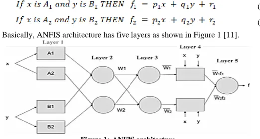
ANFIS uses a hybrid learning algorithm to identify parameters of Sugeno-type fuzzy inference system. ANFIS architecture with two inputs x and y and one output of
f is represented in Figure 1. A1 and A2 are the fuzzy memberships that fuzzified input x. B1 and B2 are also the fuzzy memberships that fuzzified the input y. The circle indicates a fixed node and square indicates an adaptive node. Sugeno ANFIS has rules of the form:
(1) (2) Basically, ANFIS architecture has five layers as shown in Figure 1 [11].
Figure 1:ANFIS architecture
The nodes in layer 1 are adaptive nodes. The outputs of this layer are the fuzzy membership grade of the inputs, which are given by:
O1,i = μAi (x) for i = 1, 2 (3)
O1,i = μBi−2 (y) for i = 3, 4 (4)
Where, μAi (x) and μBi−2 (y) are the membership grade of x and y respectively. The nodes in layer 2 are fixed. The layer 2 multiplies the incoming signals and sends the product out. The outputs of this layer are represented as:
O2,i = wi = μAi(x) μBi(y) ,i = 1, 2 (5)
The nodes in layer 3 are fixed nodes. The layer 3 calculates the ratio of the firing strengths of the rules. The output of this layer is represented as:
(6) The nodes in layer 4 are adaptive and perform the consequent of the rules. The output of layer 4 is represented as:
O4,i = wi fi = wi(pix + qiy + ri) (7)
The parameters (pi, qi, ri) of this layer are referred to the consequent parameters. The layer 5 contains only single node that computes the overall output. The output of this layer is represented as:
30
Journal of Science & Technology Vol. (21) No. (1) 2016 DOI: 10.20428/JST.21.1.4
(8)
3.2
Learning of ANFIS
The job of the learning algorithm of ANFIS system is to adjust all the adaptable parameters, which are premise parameters (ai, bi, ci) and consequent parameters (pi, qi,
ri), to achieve a high accuracy in output data prediction. Different learning algorithm
strategies with the training data are used to adapt the premise parameters and consequent parameters.
There are four methods to update the parameters, Gradient descent only, Gradient descent and one pass of LSE, Gradient descent and LSE and Sequential approximate LSE only [11].
The Gradient descent and LSE achieves a high performance compared to others. In hybrid learning rule algorithm, ANFIS uses a two pass learning algorithm [11]. Table 1 summarizes the activities in each pass.
Tabel 1:Summary of two pass learning algorithm for ANFIS
Forward pass Backward pass
Premise parameters Fixed Gradient descent
Consequent parameters
Least-squares
estimator Fixed
Signals Node outputs Error signals
4.
Load Profile and Power System Generation Of The Selected
Case Study
The following sections illustrate an overview of the load profile and the power system of the selected case study. The selected case study is the girls campus of University of Science and Technology-Yemen.
4.1
The Case Study Power System
Large consumers of electric power need more than one source additionally to the utility grid for supplying their load demands. In many cases, the large consumers of electrical power combined between several types of power sources, which called hybrid power system. Hybrid power systems achieve the integrity of power generation sources. The main reasons of using HPSs are frequently interruptions of the utility grid and random load demands, in addition to the high generation budget of the traditional power sources. The high generation budget of the traditional power sources are high fuel cost and the periodicity maintenance requirements cost.
The hybrid power system parts ;in the selected case study; are the utility grid, large diesel generator with 400KVA capacity, medium diesel generator with 200KVA, small generator with 50KVA, battery backup system with 20KVAh, and 50KWp grid-connected PV system. The main reason of taking different power sources capacity is to supply different amount of load demands with high efficiency.
31
Journal of Science & Technology Vol. (21) No. (1) 2016 DOI: 10.20428/JST.21.1.4
Furthermore, using different power sources capacities utilize the available renewable energy. In many cases, load demand is larger than capacity of many individual power sources; therefor, combination of PV generator with other sources can solve the problem of peak loads and minimize the cost of power generated and fuel consumption. HPSs reduce the fuel consumption and avoid minimizing the lifespan of the generators [14].
4.2
Load Profile
According to the state of the case study, many cases of load profile can be happened during the year. Moreover, several conditions of the case study are happening in a repetitive way during the year. Hence, some cases of the load demands are selected to give us an overview about the load profile of the case study. Four time cases have been selected, case time 1, 2, 3 and 4. The case time 1 represents the rush period of load demands, which selected in the middle of the academic term, this case time gives us an overview of the load profile about some months of the year. The case time 2 indicates the load profile of medium power consumption. The case time 2 has been selected during exams’ time, which is represents load profile for some months of the year. The case time 3 represents small power consumption, it has been selected within academics’ vacation time, during this period of time, only administrative staff is work. Hence, the most load demands are under 50KVA in this period of time. The case time 4 indicates the load profile of the festivals and holidays during the year. The following section illustrates the case time 1, which is the comprehensive case.
4.2.1
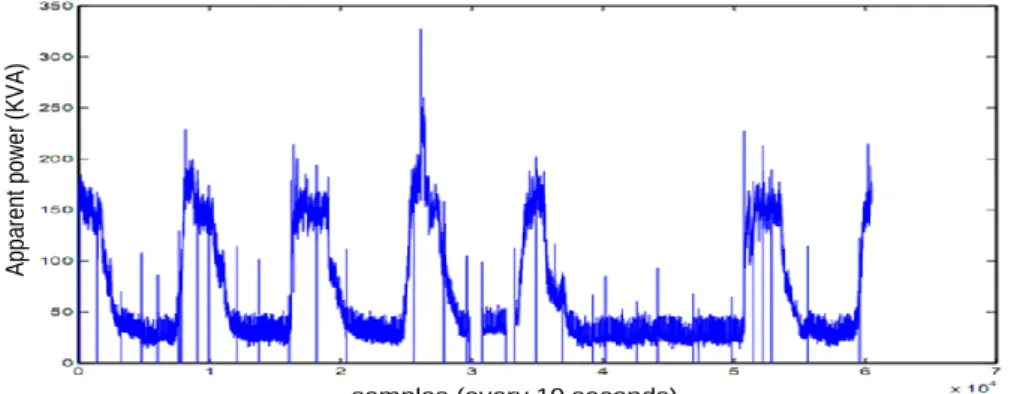
Case Time 1: Load Profile During Peak Week LoadThe selected case study has the sample of load profile as illustrated in Figure 2. The whole time interval of the load profile; that is described in Figure 2; is a week and the samples have been taken every ten seconds. As obvious from Figure 2, there are big contrast and unstable load demand during the selected week.
General load profile curve exhibits variant load demand situations, some situations frequently happened and the others rarely happened. As shown in Figure 2, the load demands will be divided into five scenarios, which are very small loads (0 - 50) KVA, small loads (50 – 150) KVA, medium loads (150 – 210) KVA, large loads (210 – 250) KVA and very large loads (250 – 350) KVA.
samples (every 10 seconds)
A pp ar en t po we r ( K V A )
32
Journal of Science & Technology Vol. (21) No. (1) 2016 DOI: 10.20428/JST.21.1.4
5.
System Description
Load profile states the overview of the case study load profile during the year. The load profile demonstrates the boundaries of the case study power consumptions. The power sources have constant power capacities except PV generator. Hence, the general determinants of the power system are obvious.
Figure 3:Block diagram of the proposed system
According to the determinants of the power system, the system has three inputs, the presence of the utility grid (UG), the amount of PV power (PV) and the amount of load demands (LD). The utility grid presence has been demonstrated by the value 1 for presence and 0 for absence. The power generated from PV generator is fuzzy amount. So, the amount of generated power from PV generator depends on solar irradiation and weather conditions [7]. Hence, the generated power by PV generator is a fuzzy amount. The load demands are random and different during the day, week and months. Referring to the case study which is an educational organization, the steady
33
Journal of Science & Technology Vol. (21) No. (1) 2016 DOI: 10.20428/JST.21.1.4
loads, long time loads and peak loads depend on the university calendar. The previous description of the system inputs states exposes that the inputs of the system are fuzzy inputs. The fuzziness is different from input to other. The fuzziness of UG is in the presence state, while the fuzziness of PV and LD is in the amount of power and generated power consumption respectively.
Outputs of the system are the backup power sources states. Different types of sources are exists, the utility grid, PV generator, diesel generators and battery backup system. The utility grid state is set as the default source as long as it is available.
6.
ANFIS Model Architecture
The block diagram of the developed system is shown in Figure 3, which has three inputs and ten outputs. The ANFIS model that optimize HPS has three inputs and ten outputs. Based on the simulation tool which is MATLAB program, the ANFIS tool only deal with one output. Moreover, the outputs are not strongly dependent on each other. Therefore, ten ANFIS models have been built and implemented for the ten outputs. All ten outputs have the same features of ANFIS structure. So, the ANFIS structure for only one output will be discussed here and the remaining outputs have the same structure.
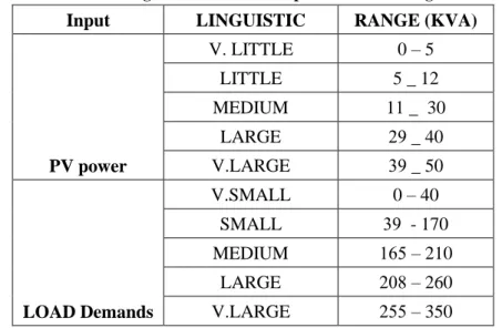
Building ANFIS model starts with selecting the number and type of membership functions (MFs) for each input. The membership functions of the first input UG are two Pi_shaped MFs. Actually, the UG input has only two values, 1 for presence and 0 for absence. PV input has five Gaussian MFs. The selection of Gaussian MF related to the smoothness of the distribution, which prevents the oscillation in decision making. Number of linguistic variables of PV and LD inputs have been determined the number of MFs of the inputs. The linguistic variables of PV and LD inputs and their ranges are illustrated in Table 2.
Tabel 2:Linguistic variables of inputs and there ranges
Input LINGUISTIC RANGE (KVA)
PV power V. LITTLE 0 – 5 LITTLE 5 _ 12 MEDIUM 11 _ 30 LARGE 92 _ 40 V.LARGE 92 _ 50 LOAD Demands V.SMALL 0 – 40 SMALL 92 - 170 MEDIUM 161 – 210 LARGE 280 – 260 V.LARGE 211 – 350
34
Journal of Science & Technology Vol. (21) No. (1) 2016 DOI: 10.20428/JST.21.1.4
PV input MFs are distributed over the ranges that exposed in Table 2. The selected ranges assumed with some reasons. The reasons include combination of more than one power generator to satisfy some cases of load demands, which helps the system to make appropriate decisions. The LD input has the MFs and ranges that exposed in Table 2, its selected ranges have been taken to the same reason of PV input.
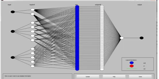
The MFs type of the output is linear and the number of them depends on the number of rules. The number of rules for the proposed ANFIS model is 50 rules, which is determined by the multiplication of the number of the inputs’
MFs
(2*5*5=50). MATLAB ANFIS model structure for one output is illustrated in Figure 4.Figure 4:ANFIS model structure
7.
Training The ANFIS Models Of The System
The main role of ANFIS technique is to get the optimum parameters of MFs that lead to generate the appropriate FIS model for the control system. Usually, the adapted parameters lead to change the shape of MFs. Many experiments and procedures have been performed to obtain the promising models of the system. Training data play major role in the accuracy of the system. Efficient and intelligent training data lead to fewer errors and accurate decision. The samples that produce the training data are combined of repetitive values, whereas there are no repetitive samples.
According to the number of membership functions of the inputs, 50 rules will be built for each ANFIS model. The training data samples can be 50 sample due to the number of rules, while the assembled training data in the introduced control system are 125 sample. The additional data samples help the system to make appropriate decisions with new data samples.
35
Journal of Science & Technology Vol. (21) No. (1) 2016 DOI: 10.20428/JST.21.1.4
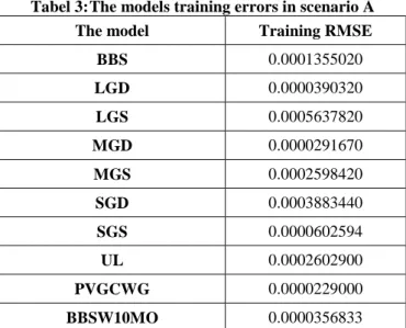
The initial and adapted MFs of the system outputs will illustrated in the following parts of this section. The training error for each model has been illustrated in Table 3.
Tabel 3:The models training errors in scenario A
The model Training RMSE
BBS 0.0001355020 LGD 0.0000390320 LGS 0.0005637820 MGD 0.0000291670 MGS 0.0002598420 SGD 0.0003883440 SGS 0.0000602594 UL 0.0002602900 PVGCWG 0.0000229000 BBSW10MO 0.0000356833
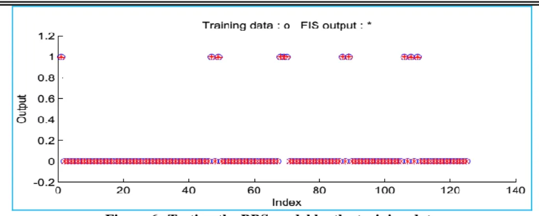
7.1 Battery backup system (BBS)
The training data that used to learn the ANFIS model of the BBS form the initial and promising inputs’ MFs of the BBS. Figure 5 illustrates inputs’ MFs before and after training of the output (BBS) and Figure 6 exposes the results of testing the BBS model by the training data.
36
Journal of Science & Technology Vol. (21) No. (1) 2016 DOI: 10.20428/JST.21.1.4
Figure 6:Testing the BBS model by the training data
7.2 Large generator direct operation (LGD)
Although the LGD output has the same inputs of the previous output, nevertheless the MFs of the LGD after training are different due to the variance of the output values. Figure 5 illustrates inputs’ MFs before and after training of the output LGD and Figure 6 exposes the results of testing the LGD model by the training data.
MFs before training MFs before training MFs before training LD (gbellmf) PV power (gaussmf) UG (pimf) MFs after training MFs after training MFs after training LD (gbellmf) PV power (gaussmf) UG (pimf)
37
Journal of Science & Technology Vol. (21) No. (1) 2016 DOI: 10.20428/JST.21.1.4
Figure 8:Testing the LGD model by the training data by the training data
7.3 Large generator standby operation (LGS)
Here also, other promising inputs’ MFs of the output LGS have been illustrated in Figure 9, where testing of the LGS model by the training data is illustrated in Figure 10.
MFs before training MFs before training MFs before training LD (gbellmf) PV power (gaussmf) UG (pimf) MFs after training MFs after training MFs after training LD (gbellmf) PV power (gaussmf) UG (pimf)
Figure 9:MFs before and after training of the output (LGS)
38
Journal of Science & Technology Vol. (21) No. (1) 2016 DOI: 10.20428/JST.21.1.4
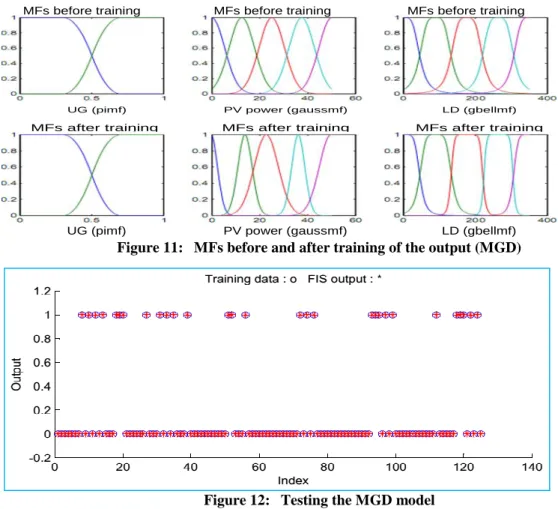
7.4 Medium generator direct operation (MGD)
Inputs’ MFs before and after training of the output MGD are illustrated in Figure 11. Testing the MGD model by the training data is illustrated in Figure 12.
MFs before training MFs before training MFs before training LD (gbellmf) PV power (gaussmf) UG (pimf) MFs after training MFs after training MFs after training LD (gbellmf) PV power (gaussmf) UG (pimf)
Figure 11: MFs before and after training of the output (MGD)
Figure 12: Testing the MGD model
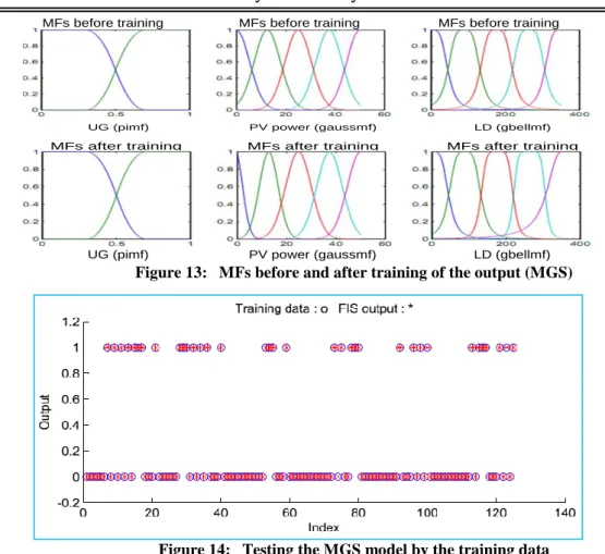
7.5 Medium generator standby operation (MGS)
Here also, other promising inputs’ MFs of the output MGS have been
illustrated in Figure 13, where testing of the MGS model by the training data is
illustrated in Figure 14.
39
Journal of Science & Technology Vol. (21) No. (1) 2016 DOI: 10.20428/JST.21.1.4 MFs before training MFs before training MFs before training LD (gbellmf) PV power (gaussmf) UG (pimf) MFs after training MFs after training MFs after training LD (gbellmf) PV power (gaussmf) UG (pimf)
Figure 13: MFs before and after training of the output (MGS)
Figure 14: Testing the MGS model by the training data
7.6 Small generator direct operation (SGD)
Inputs’ MFs before and after training of the output SGD are illustrated in Figure 15. Testing the SGD model by the training data is illustrated in Figure 16.
MFs before training MFs before training MFs before training LD (gbellmf) PV power (gaussmf) UG (pimf) MFs after training MFs after training MFs after training LD (gbellmf) PV power (gaussmf) UG (pimf)
40
Journal of Science & Technology Vol. (21) No. (1) 2016 DOI: 10.20428/JST.21.1.4
Figure 16: Testing the SGD model by the training data
7.7 Small generator standby operation (SGS)
Inputs’ MFs before and after training of the output SGS are illustrated in Figure 17. Testing the SGS model by the training data is illustrated in Figure 18.
MFs before training MFs before training MFs before training LD (gbellmf) PV power (gaussmf) UG (pimf) MFs after training MFs after training MFs after training LD (gbellmf) PV power (gaussmf) UG (pimf)
Figure 17: MFs before and after training of the output (SGS)
41
Journal of Science & Technology Vol. (21) No. (1) 2016 DOI: 10.20428/JST.21.1.4
7.8 Unnecessary loads (UL)
Inputs’ MFs before and after training of the output UL are illustrated in Figure 19. Testing the UL model by the training data is illustrated in Figure 20.
MFs before training MFs before training MFs before training LD (gbellmf) PV power (gaussmf) UG (pimf) MFs after training MFs after training MFs after training LD (gbellmf) PV power (gaussmf) UG (pimf)
Figure 19: MFs before and after training of the output (UL)
Figure 20: Testing the UL model by the training data
7.9 PV grid-connected with generators (PVGCWG)
Inputs’ MFs before and after training of the output (PVGCWG) are illustrated in Figure 21. Testing the (PVGCWG) model by the training data is illustrated in Figure 22.
MFs before training MFs before training MFs before training LD (gbellmf) PV power (gaussmf) UG (pimf) MFs after training MFs after training MFs after training LD (gbellmf) PV power (gaussmf) UG (pimf)
42
Journal of Science & Technology Vol. (21) No. (1) 2016 DOI: 10.20428/JST.21.1.4
Figure 22: Testing the (PVGCWG ) model by the training data
7.10 Battery backup system with 10 mints operation (BBSW10MO)
Inputs’ MFs before and after training of the output BBSW10MO are illustrated in Figure 23. Testing the (BBSW10MO) model by the training data is illustrated in Figure 24. MFs before training MFs before training MFs before training LD (gbellmf) PV power (gaussmf) UG (pimf) MFs after training MFs after training MFs after training LD (gbellmf) PV power (gaussmf) UG (pimf)Figure 23: MFs before and after training of the output (BBSW10MO)
43
Journal of Science & Technology Vol. (21) No. (1) 2016 DOI: 10.20428/JST.21.1.4
8.
Conclusion and Future Work
This paper has introduced a new approach to improve the performance of Hybrid Power Systems (HPSs) based on Adaptive Neuro Fuzzy Inference System (ANFIS). Referring to the system outputs, ten ANFIS models have been trained and simulated using MATLAB. During the training process, all system models have achieved values of RMSE around zero, where the maximum RMSE value is 0.000563 for the LGS model. The obtained values of RMSE indicate that the system is capable to make the appropriate decisions with similar data of the training data. The modified MFs indicate that the system can predict the appropriate decisions with new data inputs. The introduced approach acquired high accuracy performance with the testing data. The proposed future work, study the running cost of the hybrid power system without using the introduced fuzzy control system and with using it. The study of the cost highlights the importance of the control system.
9.
References
[1] B. M. M. K. Shivarama Krishna, and Dr. M. Padma Lalitha, "Dynamic Modeling and Control of Grid Connected Hybrid Wind/PV Generation System," International Journal of Engineering Research and Development, vol. 10, no. 5, 2014.
[2] M. S. I. Abdel-Qader, "Simulation of a Hybrid Power System Consisting of Wind Turbine, PV, Storage Battery and Diesel Generator with Compensation Network: Design, Optimization and Economical Evaluation," An-Najah National University, 2008. [3] D. K. Lal, B. B. Dash, and A. K. Akella, "Optimization of
PV/Wind/Micro-Hydro/Diesel Hybrid Power System in HOMER for the Study Area," International Journal on Electrical Engineering and Informatics, vol. 3, no. 3, 2011.
[4] M. N. Nashed and M. N. Eskander, "Intelligent Load Management And Optimal Operation of a Wind-Diesel Hybrid Power System," Journal of Next Generation Information Technology (JNIT), vol. 4, no. 9, p. 9, 2013.
[5] S. Singh and A. Singh, "Rural Home Energy Management by Fuzzy Control Model for Solar (PV)-Grid/DG Power System in India," Journal of Electrical and Control Engineering (JECE), vol. 2, no. 1, pp. 29-33, 2012.
[6] R. Malik, "Studies and development of a new intelligent controller based hybrid (solar & conventional) power management system," JADAVPUR UNIVERSITY, 2012. [7] A. M. Aldobhani and R. John, "Maximum power point tracking of PV system
using ANFIS prediction and fuzzy logic tracking," Citeseer, 2008.
[8] M. Izadbakhsh, A. Rezvani, and M. Gandomkar, "Improvement of microgrid dynamic performance under fault circumstances using ANFIS for fast varying solar radiation and fuzzy logic controller for wind system," Archives of Electrical Engineering, vol. 63, no. 4, pp. 551-578, 2014.
[9] R. K. Kharb1, M. F. A. , and S. L. S. , "Design and Implementation of ANFIS based MPPT Scheme with Open Loop Boost Converter for Solar PV Module "
44
Journal of Science & Technology Vol. (21) No. (1) 2016 DOI: 10.20428/JST.21.1.4
International Journal of Advanced Research in Electrical, Electronics and Instrumentation Engineering vol. 3, no. 1, 2014.
[10] S.-H. Lee, S.-J. Lee, and K.-I. Moon, "Adaptive Neural Fuzzy Reasoning Model for Smart Grid," Advanced Science and Technology Letters, vol. 42, 2013.
[11] J.-S. Jang, "ANFIS: adaptive-network-based fuzzy inference system," Systems, Man and Cybernetics, IEEE Transactions on, vol. 23, no. 3, pp. 665-685, 1993. [12] J.-S. Jang and C.-T. Sun, "Neuro-fuzzy modeling and control," Proceedings of
the IEEE, vol. 83, no. 3, pp. 378-406, 1995.
[13] J. Jang, C. Sun, and E. Mizutani, "Neuro-fuzzy and soft computing. 1997," PTR Prentice Hall, 1997.
[14] H. Tazvinga, X. Xia, and J. Zhang, "Minimum cost solution of photovoltaic– diesel–battery hybrid power systems for remote consumers," Solar Energy, vol. 96, pp. 292-299, 2013.