UNIFIED FACILITIES CRITERIA (UFC)
APPROVED FOR PUBLIC RELEASE; DISTRIBUTION UNLIMITED
DESIGN: SIGN STANDARDS
UNIFIED FACILITIES CRITERIA (UFC) DESIGN: SIGN STANDARDS
Any copyrighted material included in this UFC is identified at its point of use. Use of the copyrighted material apart from this UFC must have the permission of the copyright holder.
U.S. ARMY CORPS OF ENGINEERS
NAVAL FACILITIES ENGINEERING COMMAND
AIR FORCE CIVIL ENGINEER CENTER (Preparing Activity)
Record of Changes (changes are indicated by \1\…/1/)
Change No. Date Location
1 May 2014 Revised paragraph 2-2.5; revised Figures 4-1 through
4-6, 4-10, 4-11, 4-13 through 4-15
2 October 2014 Revised paragraph 3-7.2; revised Figures 3-12, 3-13,
4-1, and 4-2
FOREWORD
The Unified Facilities Criteria (UFC) system is prescribed by MIL-STD 3007 and provides planning, design, construction, sustainment, restoration, and modernization criteria, and applies to the Military Departments, the Defense Agencies, and the DoD Field Activities in accordance with USD (AT&L) Memorandum dated 29 May 2002. UFC will be used for all DoD projects and work for other customers where appropriate. All construction outside of the United States is also governed by Status of Forces Agreements (SOFA), Host Nation Funded Construction Agreements (HNFA), and in some instances, Bilateral Infrastructure Agreements (BIA.)
Therefore, the acquisition team must ensure compliance with the most stringent of the UFC, the SOFA, the HNFA, and the BIA, as applicable.
UFC are living documents and will be periodically reviewed, updated, and made available to users as part of the Services’ responsibility for providing technical criteria for military
construction. Headquarters, U.S. Army Corps of Engineers (HQUSACE), Naval Facilities Engineering Command (NAVFAC), and Air Force Civil Engineer Center (AFCEC) are responsible for administration of the UFC system. Defense agencies should contact the preparing service for document interpretation and improvements. Technical content of UFC is the responsibility of the cognizant DoD working group. Recommended changes with supporting rationale should be sent to the respective service proponent office by the following electronic form: Criteria Change Request. The form is also accessible from the Internet sites listed below. UFC are effective upon issuance and are distributed only in electronic media from the following source:
• Whole Building Design Guide web site http://dod.wbdg.org/.
Refer to UFC 1-200-01, General Building Requirements, for implementation of new issuances on projects.
AUTHORIZED BY:
JAMES C. DALTON, P.E. JOSEPH E. GOTT, P.E.
Chief, Engineering and Construction Chief Engineer
U.S. Army Corps of Engineers Naval Facilities Engineering Command
JOE SCIABICA, SES MICHAEL McANDREW
Director Director, Facilities Investment and Management
Air Force Civil Engineer Center Office of the Deputy Under Secretary of Defense
UNIFIED FACILITIES CRITERIA (UFC) REVISION SUMMARY SHEET Document: UFC 3-120-01, Design: Sign Standards
Superseding: UFC 3-120-01, Air Force Sign Standards
Description: This document is a wholesale change from the previous version, which was based on AFPAM 32-1097, dated 1 November 1997.
Reasons for Document:
• Purpose: The purpose of this change is to provide clear standards and guidelines for all Service branches to develop consistent signage programs. • Application: This UFC is applicable to military installations worldwide.
• Need: This UFC is needed to bring uniformity to many different types of signage used at military installations across the DoD.
• Reasons for Revised UFC: The previous version of this UFC addressed only Air Force sign standards. That document included outdated information that
provided little assistance in the implementation of new or replacement signs. Impact: The following direct benefits will result from publication of this UFC:
• Initial Costs: The costs of implementing new or replacement signs may be lower due to the synergies found in the design guidance of this UFC.
• Life Cycle Costs: Effective application of the design guidance provided will reduce maintenance and minimize overall life cycle costs.
• Safety: Effective application of the strategies in this UFC will improve safety and help ensure building code compliance.
• Convenience: Service members, civilian employees, contractors, and visitors will enjoy improved wayfinding and less stress associated with poor signage.
• Public Image: Compliance with the Service branch identification guidelines in this UFC will help contribute to the positive reinforcement of the brand identity for each Service branch.
TABLE OF CONTENTS
CHAPTER 1 GENERAL INFORMATION ... 1
1-1 PURPOSE AND SCOPE. ... 1
1-1.1 Background. ... 1
1-1.2 Intended Use. ... 1
1-2 GENERAL. ... 1
1-2.1 Sustainability. ... 2
1-3 CODES AND STANDARDS ... 2
1-3.1 Exterior Sign Codes and Requirements. ... 2
1-3.2 Interior Sign Codes and Requirements. ... 3
1-3.2.1 ABA Accessibility Standard. ... 3
1-3.2.2 International Building Code. ... 3
1-3.2.3 National Fire Protection Association. ... 3
1-3.2.4 UFGS 10 14 00.20. ... 4
CHAPTER 2 DESIGN STANDARDS ... 5
2-1 GRAPHICS STANDARDS. ... 5
2-1.1 Service Branch Logo Identification. ... 5
2-2 FONT STANDARDS. ... 7
2-2.1 Helvetica Neue – 95 Black ... 8
2-2.2 Helvetica Neue – 85 Heavy ... 8
2-2.3 Helvetica Neue – 75 Bold ... 8
2-2.4 Helvetica Neue – 65 Medium ... 9
2-2.5 Helvetica Neue – 55 Roman ... 9
2-2.6 Alternative Fonts. ... 9
2-2.7 Letter Spacing. ... 9
CHAPTER 3 EXTERIOR SIGN STANDARDS ... 11
3-1 EXTERIOR SIGN DESIGN GUIDANCE. ... 11
3-1.1 Exterior Sign Types. ... 11
3-1.2 Prohibited Exterior Signs. ... 11
3-1.3 Historic Signs. ... 11
3-1.4 Exterior Color Standards. ... 12
3-1.5 Engineering and Shop Drawings. ... 12
3-2 INSTALLATION AND GATE IDENTIFICATION SIGNS. ... 12
3-2.1 Message Content. ... 12
3-2.3 Illumination. ... 13
3-2.4 Primary Installation and Gate Identification Signs. ... 13
3-2.5 Secondary Installation and Gate Identification Signs. ... 17
3-2.6 Wall-Mounted Installation Identification Signs. ... 18
3-2.7 Tertiary Gate and Entrance Signs. ... 19
3-3 BUILDING IDENTIFICATION SIGNS. ... 19
3-3.1 Freestanding Building Identification Signs. ... 19
3-3.1.1 Materials and Colors. ... 21
3-3.1.2 Street Address and Building Numbers. ... 22
3-3.2 Building Entrance Signs. ... 22
3-3.2.1 Materials and Colors. ... 24
3-3.3 Building Entrance Signs on Glass. ... 24
3-3.4 Building-Mounted Identification. ... 25
3-3.4.1 Materials and Colors. ... 25
3-3.4.2 Placement. ... 26
3-3.5 Commercial Signs. ... 26
3-3.6 Centralized Facilities Freestanding Identification Signs. ... 26
3-3.6.1 Specialty Community Identification Signs. ... 27
3-3.7 Water Tower Signage and Graphics. ... 27
3-4 TRAFFIC CONTROL DEVICES. ... 28
3-4.1 Fabrication and Installation. ... 28
3-4.2 Access Control Point/Entry Control Facility Signs. ... 29
3-4.3 Speed Limit Signs. ... 29
3-4.4 Street Name Signs. ... 29
3-4.5 Reserved and Accessible Parking Signs. ... 29
3-5 DIRECTIONAL AND WAYFINDING SIGNS. ... 29
3-5.1 General Guidelines. ... 29
3-5.1.1 Materials and Colors. ... 30
3-5.1.2 Message Limitations. ... 30
3-5.1.3 Sign Placement and Installation Details. ... 30
3-5.2 Orientation Map and Wayfinding Signs. ... 31
3-6 MANDATORY AND PROHIBITORY SIGNS. ... 32
3-6.1 Accessibility Pathway and Entrance Signs. ... 32
3-7 INFORMATIONAL AND MOTIVATIONAL SIGNS. ... 32
3-7.2 Electronic Message Signs. ... 33
3-7.3 Exhibit Signs. ... 34
3-7.4 Specialty Informational Signs. ... 34
3-7.5 Construction Project Identification Signs. ... 34
CHAPTER 4 INTERIOR SIGN STANDARDS ... 35
4-1 INTERIOR SIGN DESIGN Requirements. ... 35
4-1.1 Interior Sign Types. ... 35
4-1.2 Interior Signage Objectives. ... 36
4-1.3 Materials and Colors. ... 36
4-1.4 Room Numbering. ... 36
4-1.5 Medical-Related Facilities. ... 37
4-1.6 Owner Education and Maintenance Manuals. ... 37
4-2 ROOM, SPACE, AND WORKSTATION IDENTIFICATION SIGNS. ... 37
4-2.1 Room Identification Signs. ... 37
4-2.2 Workstation Identification Signs. ... 39
4-2.2.1 Workstation Sign Installation. ... 40
4-2.3 Restroom Identification Signs. ... 41
4-2.4 Stair Identification Signs. ... 43
4-2.5 Typical Room and Space Identification Sign Installations. ... 44
4-3 LIFE SAFETY SIGNS. ... 46
4-3.1 Stairway Life Safety Signs. ... 46
4-3.2 Tactile Exit Signs. ... 47
4-3.3 Tactile Stairway Level Indicator Signs. ... 48
4-3.4 Life Safety Door-Mounted Signs. ... 48
4-3.5 Elevator Egress Signs. ... 49
4-3.6 Tactile Elevator Hoist Way Level Indicator Signs. ... 50
4-3.7 Additional Life Safety Signs. ... 51
4-4 INTERIOR DIRECTIONAL SIGNS. ... 51
4-4.1 Wall-Mounted Directional Signs. ... 51
4-4.2 Ceiling-Mounted Directional Signs. ... 52
4-4.3 Flag-Mounted Signs. ... 53
4-5 BUILDING DIRECTORIES. ... 54
4-5.1 Electronic Directories and Wayfinding Systems. ... 54
4-6 INTERIOR MANDATORY AND PROHIBITORY SIGNS. ... 54
4-8 UNIT IDENTIFICATION AND MORALE SIGNS. ... 56
APPENDIX A REFERENCES ... 57
APPENDIX B GLOSSARY ... 59
FIGURES Figure 2-1 Army Logo Identification. ... 5
Figure 2-2 Air Force Logo Identification. ... 6
Figure 2-3 Navy Logo Identification. ... 6
Figure 2-4 Marine Corps Logo Identification. ... 7
Figure 2-5 Joint Base Logo Identification. ... 7
Figure 2-6 Helvetica Neue – 95 Black. ... 8
Figure 2-7 Helvetica Neue – 85 Heavy. ... 8
Figure 2-8 Helvetica Neue – 75 Bold. ... 8
Figure 2-9 Helvetica Neue – 65 Medium. ... 9
Figure 2-10 Helvetica Neue – 55 Roman. ... 9
Figure 2-11 Installation Name Letter Spacing. ... 9
Figure 2-12 Letter Spacing Standards. ... 10
Figure 3-1 Installation and Gate Identification Sign Accent Colors. ... 13
Figure 3-2 Primary Installation and Gate Identification Sign Fabrication. ... 14
Figure 3-3 Primary Installation and Gate Identification Signs. ... 15
Figure 3-4 Primary Installation and Gate Sign Layout Details. ... 16
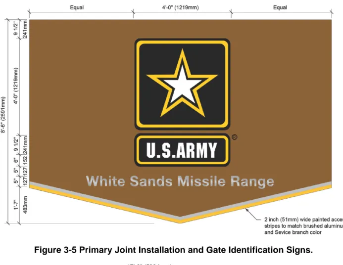
Figure 3-5 Primary Joint Installation and Gate Identification Signs. ... 16
Figure 3-6 Primary Joint Installation Sign Layout Details. ... 17
Figure 3-7 Secondary Installation Identification Signs. ... 17
Figure 3-8 Secondary Installation Sign Layout Details. ... 18
Figure 3-9 Wall-Mounted Installation Identification Sign. ... 19
Figure 3-10 Freestanding Building Identification Signs. ... 20
Figure 3-11 Freestanding Building Identification Sign Layouts. ... 21
Figure 3-12 Building Entrance Signs. ... 22
Figure 3-13 Building Entrance Sign Layouts. ... 23
Figure 3-14 Building-Mounted Entry Sign Placement. ... 23
Figure 3-15 Building Identification for Glass Entrances. ... 25
Figure 3-16 Centralized Facilities Freestanding Identification Signs. ... 26
Figure 3-17 Water Tower Signs. ... 28
Figure 3-18 Pedestrian Directional Signs. ... 31
Figure 3-19 Orientation Map Signs. ... 32
Figure 4-1 Room Identification Signs. ... 38
Figure 4-2 Permanent Room Identification Signs. ... 39
Figure 4-3 Workstation Identification Signs. ... 40
Figure 4-4 Accessible Restroom Identification Signs. ... 41
Figure 4-5 Non-Accessible Restroom Identification Signs. ... 42
Figure 4-6 Stair Identification Signs. ... 44
Figure 4-7 Typical Interior Sign Installations. ... 45
Figure 4-8 Typical Sign Installations on Glass. ... 46
Figure 4-9 Stairway Life Safety Information. ... 47
Figure 4-10 Tactile Exit Signs. ... 48
Figure 4-11 Tactile Stairway Level Indicators. ... 48
Figure 4-12 Life Safety Door Signs. ... 49
Figure 4-13 Elevator Egress Signs. ... 50
Figure 4-14 Elevator Hoist Way Level Indicators. ... 51
Figure 4-16 Ceiling-Mounted Directional Signs. ... 53
Figure 4-17 Flag-Mounted Signs. ... 53
Figure 4-18 Building Directory. ... 54
Figure 4-19 Mandatory and Prohibitory Signs. ... 55
Figure 4-20 Informational and Motivational Signs. ... 55
CHAPTER 1 GENERAL INFORMATION
1-1 PURPOSE AND SCOPE.
This UFC provides criteria for new and replacement signage appropriate for each Service branch. It establishes requirements for the graphic identification of registered trademarks that are easily recognized in the community. It also provides criteria for standardizing sign materials, colors, styles, and placement throughout an installation. Information on unique sign programs and design requirements of local projects must be obtained at the installation level. Some installations may deviate from these general standards in order to be compatible with their existing signage. Alteration and
renovation projects should update existing signage to meet the guidance and criteria provided in this UFC where possible. Non-conforming signs should be replaced when their useful life has ended or modified as required to be compatible with the intent of these standards where practical and economically justifiable.
1-1.1 Background.
This UFC was developed through the collaborative efforts of the U.S. Army Corps of Engineers (USACE), the Air Force Civil Engineer Center (AFCEC), and Naval Facilities Engineering Command (NAVFAC). The intent of this UFC is to provide comprehensive criteria for evaluating, planning, programming, and implementing interior and exterior signs for all military and other Department of Defense (DoD) installations worldwide. This UFC uses non-government standards to the greatest extent possible.
1-1.2 Intended Use.
This UFC applies to the design of all new construction projects, including additions, alterations, and renovation projects on military installations of the Army, Air Force, Navy, and Marines, in the continental United States (CONUS) and overseas
(OCONUS). This UFC may also apply to off-installation facilities of these four Service branches, such as recruiting stations or other similar facilities. This UFC does not apply to visual air navigation facility signs placed in and around airfield environments to
provide information for operating aircraft. Some installations may require unique sign solutions that reflect their cultural heritage or historical significance, as appropriate.
1-2 GENERAL.
Signs are a highly visible component of the built environment and the public impression expressed by military installations. Each installation must establish both interior and exterior sign standards as part of their Installation Planning Standards (IPS), which include Navy Installation Appearance Plans (IAP), Army Installation Design Guides (IDG), and Air Force Facilities Excellence Guides (FEG). These standards will help provide visual and functional signage consistency for all installations. This consistency will also help improve wayfinding by providing familiar signage components and
directional information. Sign programs should be designed with materials and
fabrication techniques that maximize the durability of signs and minimize maintenance. Effective sign programs will reduce the number of signs on each installation to the absolute minimum required for directions, identification, and customer service. This
eliminates visual clutter and results in an efficient, cost-effective, and attractive system that creates a unified professional appearance for all military installations. Efficient signage and wayfinding programs help provide support for installation-specific mission requirements. Using sign standards will simplify the design/procurement process and reduce construction/maintenance costs.
1-2.1 Sustainability.
The sign contractor must coordinate with the project team to ensure signage materials and components comply with current DoD or Service-specific sustainable design policies, as applicable.
1-3 CODES AND STANDARDS
This UFC is intended to supplement, not replace code requirements and standards, which continue to be the authority for the issues to which they apply.
1-3.1 Exterior Sign Codes and Requirements.
Most exterior signs require approvals and/or permitting at the installation level before installation. Exterior signage programs require compliance with a wide variety of sometimes conflicting criteria, such as:
• American Association of State Highway and Transportation Officials (AASHTO)
Roadside Design Guide
• Architectural Barriers Act Accessibility Standard for Department of Defense Facilities (ABAAS)
• Federal Highway Administration (FHWA) Manual on Uniform Traffic Control Devices (MUTCD)
• FHWA Standard Highway Signs
• Institute of Transportation Engineers (ITE) Traffic Control Devices Handbook
• Surface Deployment and Distribution Command Transportation Engineering Agency (SDDCTEA) DoD supplement to the MUTCD
• SDDCTEA Pamphlet 55-14 • SDDCTEA Pamphlet 55-15 • SDDCTEA Pamphlet 55-17 • UFC 2-100-01
• UFC 3-535-01
• Unified Facilities Guide Specifications (UFGS) 10 14 01
The location and placement of all exterior signs must comply with guidance provided in the MUTCD.
1-3.2 Interior Sign Codes and Requirements.
Interior signage programs require compliance with a wide variety of different code issues and requirements, such as:
• ABAAS
• International Building Code (IBC)
• National Fire Protection Association (NFPA) 101 • UFGS 10 14 00.20
These building codes have specific requirements regarding signage and vary with the building design and other details.
1-3.2.1 ABA Accessibility Standard.
The ABAAS has many requirements that specifically address interior signage, such as: • Permanent room and space identification
• Requirements for Braille and tactile characters on certain signs • Sign mounting height and location requirements
• Utilization of the international symbol of accessibility (ISA) • Specialized elevator signage requirements
These specialized requirements have been considered for the interior sign design parameters provided in Chapter 4.
1-3.2.2 International Building Code.
The IBC has many requirements that specifically address interior signage, such as: • Stair identification
• Two-way communication systems • Elevator life safety signs
• Means of egress signs • Maximum occupancy signs
1-3.2.3 National Fire Protection Association.
Comply with the interior signage requirements of NFPA 101. These requirements address life safety issues, such as:
• Stair identification and stairway landing information
• Tactile level identification requirements (in specific circumstances) • Tactile exit sign requirements
• Egress identification and information requirements • Fire extinguisher identification and information • Elevator sign requirements
1-3.2.4 UFGS 10 14 00.20. This UFGS addresses such issues as:
• Sustainability requirements • Submittals
• Warranty
• Various types of interior signs • Installation requirements • Protection and cleaning
CHAPTER 2 DESIGN STANDARDS
2-1 GRAPHICS STANDARDS.
Standardization of graphic and text information used on military installation signs helps establish consistent visual communication and brand identity. The graphic standards in this chapter provide general guidelines for most sign message requirements, such as the use of logos, seals, fonts, and colors.
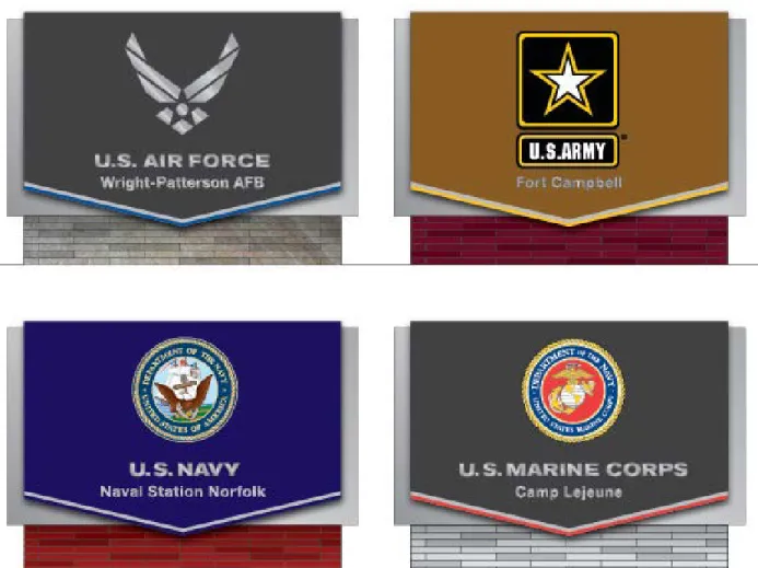
2-1.1 Service Branch Logo Identification.
Service branch logo identification includes seals, symbols, and text that are registered trademarks. Use the approved Service branch seals and text of the Army, Navy, and Marines on installation identification signs as specified in this UFC in Figures 2-1 through 2-5. Use the approved Air Force symbol and text on installation identification signs as specified in this UFC. Restrict the use of these logos to installation
identification signs and water towers. There are no such restrictions on the use of these logos on interior signs. The logos must not be altered or modified in any way.
Figure 2-2 Air Force Logo Identification.
Figure 2-4 Marine Corps Logo Identification.
Figure 2-5 Joint Base Logo Identification.
2-2 FONT STANDARDS.
The term “font” is used in this UFC for references to typography. Most sign messages should use upper- and lowercase text for optimum readability. Use the Helvetica Neue family of fonts. The font standards for sign message content include the following:
• Helvetica Neue – 95 Black • Helvetica Neue – 85 Heavy • Helvetica Neue – 75 Bold • Helvetica Neue – 65 Medium • Helvetica Neue – 55 Roman
This family of fonts provides a hierarchy for messages used on signs. Use the Adobe OpenType family of fonts to provide the maximum flexibility on both the Macintosh and
PC operating systems. Traffic control signs must follow the Standard Alphabets for
Highway Signs and Pavement Markings published by the FHWA and used in conjunction with the MUTCD.
2-2.1 Helvetica Neue – 95 Black
Use the font Helvetica Neue 95 Black (see Figure 2-6) in all applications for letter descriptions of the Air Force, Army, Navy, Marines, and joint bases on installation/gate identification signs and water towers.
Figure 2-6 Helvetica Neue – 95 Black.
2-2.2 Helvetica Neue – 85 Heavy
Use Helvetica Neue 85 Heavy (see Figure 2-7) for the names of military units on freestanding primary building identification signs and building-mounted identification letters.
Figure 2-7 Helvetica Neue – 85 Heavy.
2-2.3 Helvetica Neue – 75 Bold
Use Helvetica Neue 75 Bold (see Figure 2-8) to identify the installation name on
installation/gate identification signs. This font may also be used as the larger font where a hierarchy of typestyles is beneficial.
2-2.4 Helvetica Neue – 65 Medium
Helvetica Neue 65 Medium (see Figure 2-9) is the approved font for primary or “headline” messages on both interior and exterior signs unless otherwise specified.
Figure 2-9 Helvetica Neue – 65 Medium.
2-2.5 Helvetica Neue – 55 Roman
Helvetica Neue 55 Roman (see Figure 2-10) is the approved font for secondary or “body
text” messages on both interior and exterior signs unless otherwise specified. \1\ This
font should also be used for all tactile messages on interior signs. /1/
Figure 2-10 Helvetica Neue – 55 Roman.
2-2.6 Alternative Fonts.
Alternative fonts may be used on signs for historic buildings or installations with unique architectural character. Alternative fonts must comply with ABAAS when used for tactile characters associated with Braille requirements.
2-2.7 Letter Spacing.
Appropriate letter spacing is important for consistency and the visual appearance of message content on signs. Kerning refers to the spacing between letters and optical kerning of letters is desired for digital sign message layouts. Comply with the letter spacing examples provided below for all installation and gate identification signs. All other sign message requirements will use optical kerning and zero letter spacing. Refer to Figures 2-11 and 2-12 for examples.
CHAPTER 3 EXTERIOR SIGN STANDARDS 3-1 EXTERIOR SIGN DESIGN GUIDANCE.
Provide exterior signage as part of a total wayfinding system that includes directional guide signs, building identification signs, pedestrian directional signs, street signs, and orientation maps. Develop installation-specific sign designs in accordance with this UFC, giving consideration to the existing IPS, cultural heritage, regional influences, and historical significance. Signs should coordinate with nearby landscape and structures. Design exterior signs for maximum durability and sustainability based upon regional weather impacts. Sign message panels should be easy to update or replace to allow for flexibility of future message updates. Integrate new signs with existing signs to provide the most cost-effective and practical solutions for each facility or installation. A
standardized sign system ensures consistency, improves wayfinding, and is compatible with existing base standards.
3-1.1 Exterior Sign Types.
Develop a standard family of installation-specific sign designs in accordance with this UFC and any specific requirements defined in the IPS. Integrate new signs with existing signs to provide the most cost-effective and practical solutions for each facility or installation. There are six basic categories of exterior signs:
• Installation and gate identification • Building identification
• Traffic control devices • Directional and wayfinding • Mandatory and prohibitory • Informational and motivational 3-1.2 Prohibited Exterior Signs.
Prohibited signs include any sign with animated, blinking, chasing, flashing, or moving effects. Other types of prohibited signs include rotating signs, windblown or inflated signs, neon signs, and portable signs. Specific prohibitions on certain sign types may also be established at the installation level. These restrictions do not apply to traffic control devices.
3-1.3 Historic Signs.
Specialty historic signs for facilities on the National Historic Register or within a historic district must be coordinated and approved through the state historic preservation office (SHPO). These are freestanding and wall-mounted exterior signs that may use a special typeface, materials, or fabrication techniques to complement the character of historic buildings.
3-1.4 Exterior Color Standards.
The goal of this UFC is to establish a consistent color scheme for all installation and building signs that works for all Service branches. A consistent dark background should be used for standard installation and gate identification signs, with light text to provide sufficient contrast, to meet all visibility and required legibility objectives. Accent colors help reinforce the brand identity of the Service branch.
Service branch-specific color schemes are permitted exceptions to the standard color scheme where needed to maintain consistency with existing sign programs, IPS, or other special considerations at some installations. These color standards and special Service branch exceptions do not apply to traffic control signs that have color and material requirements specified in the MUTCD.
3-1.5 Engineering and Shop Drawings.
All signs, foundations, and connections must be engineered to resist wind loads and thermal movement according to the local climate requirements without distortions and excessive deflections. Shop drawings submitted by the sign contractor must include fabrication details such as elevations, message layouts, sections, side views, plan views, mounting details, and electrical or communication details. Submittals for all freestanding signs must include design calculations and the signed seal of a registered structural engineer licensed in the required area or follow approved state department of transportation standards to ensure compliance with all design and load requirements. Shop drawings must illustrate all means of mounting and attachment for proper
coordination for connections to building structures.
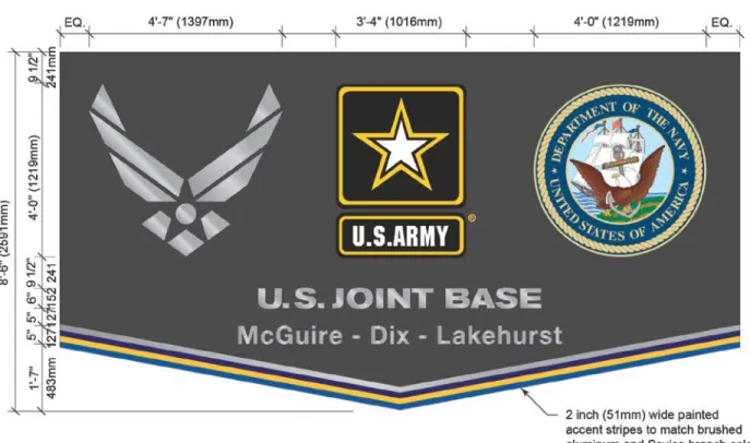
3-2 INSTALLATION AND GATE IDENTIFICATION SIGNS.
Provide installation and gate identification signs according to the design guidelines provided in this UFC to help provide consistency for installation identification signs among all Service branches. These sign designs also address joint Service installation identification issues.
3-2.1 Message Content.
These signs may contain graphic information on one or both sides, depending upon the orientation of the sign and visibility requirements. These signs contain only the
following information:
• Service branch logo or seals.
• Service branch or “U.S. Joint Base” identification text in all caps. The font
must be Helvetica Neue 95 Black. The logo for the lead Service branch of a joint base must be mounted on the left side of the sign.
• Installation name in upper- and lowercase letters. Font must be Helvetica
Neue 75 Bold. The name for the lead Service branch of a joint base must be mounted on the left side of the sign and must match the logo placement.
• Optional gate identification information may be added to the base of the sign. The font must be Helvetica Neue 65 Medium.
3-2.2 Materials and Colors.
The sign and background material should be fabricated from aluminum with a painted finish. All logo symbols and seals must be 0.5 inch (13 millimeters [mm]) thick and fabricated from highly durable materials with full color graphics, except the Air Force logo must be brushed aluminum. All letterforms must be constructed of 0.5-inch (13-mm) -thick aluminum. Use a paint to match a “brushed aluminum” finish for the center part of the sign cabinet. Provide a dark bronze painted finish for the background of the sign face unless there are installation-specific color standards. The supporting structure materials may vary to match the architectural character of the surrounding environment or installation-specific standards.
Service branch-specific color schemes are permitted exceptions to the standard color scheme where needed to maintain consistency with existing sign programs. These special considerations should be established in the IPS. Provide a vertical brushed finish with a factory-applied coating to aluminum letterforms on dark backgrounds. Provide dark painted letterforms if using a light-colored sign background to provide sufficient contrast and allow these signs to meet all required visibility and legibility objectives. These color standards and special Service branch exceptions do not apply to traffic control signs that have color and material requirements specified in the
MUTCD. Accent colors shown in Figure 3-1 are used to help reinforce the brand identity of each Service branch.
Figure 3-1 Installation and Gate Identification Sign Accent Colors.
3-2.3 Illumination.
Provide external illumination for all primary, secondary, and wall-mounted installation entrance signs where required for visibility. Use high-efficiency floodlights. Minimize the use of illuminated signs to reduce initial costs, prevent maintenance issues, and avoid driving distractions.
3-2.4 Primary Installation and Gate Identification Signs.
The structure supporting the sign may vary to complement the predominant
architectural style of the installation, but the design of the sign itself must conform to Figures 3-2 through 3-9 to the maximum extent practical. Installation and gate identification signs at the entrances to installations are the only signs that will incorporate the brand identity of each Service branch.
Figure 3-4 Primary Installation and Gate Sign Layout Details.
Figure 3-6 Primary Joint Installation Sign Layout Details.
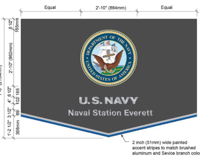
3-2.5 Secondary Installation and Gate Identification Signs.
Secondary installation and gate identification signs are used to identify secondary installation entrances that receive high volumes of traffic (see Figures 3-7 through 3-9). These entrances are primarily for active duty and other DoD personnel with proper identification. These signs must use the same materials and information as the primary installation identification signs except they must be slightly smaller in size.
Supplemental messages may be provided on the sign base, such as gate identification or hours of operation.
Figure 3-8 Secondary Installation Sign Layout Details.
3-2.6 Wall-Mounted Installation Identification Signs.
Installation identification signs may need to be placed on existing walls, gates, or buildings at or near the main installation entrances to identify and introduce the installation to visitors. The fabrication techniques, materials, and colors should be consistent with freestanding installation identification entrance gate signs. These signs should use the background materials as shown to provide a consistent background for the symbols and letterforms regardless of the color of the object where it may be installed. Provide installation identification mounted on an aluminum sign panel because it requires fewer holes to be drilled into the existing structure than individual logo symbol/letters, resulting in less damage to the structure in the event of a future name change.
Figure 3-9 Wall-Mounted Installation Identification Sign.
3-2.7 Tertiary Gate and Entrance Signs.
Tertiary gate and installation entrance signs are used to identify non-public access control points, such as commercial/delivery gates. Use MUTCD standard guide signs to direct vehicles to these entrances. Message content should include the installation name and the function of the tertiary entrance.
3-3 BUILDING IDENTIFICATION SIGNS.
Building identification signs are used inside the installation to provide information about buildings, major tenants within buildings, areas within the installation, and organizational or functional units. Different sizes and design elements are used to identify the different organizational levels. The signs should carry one unit name and any secondary
information to identify the unit component (such as headquarters) and may also include a street address. No unit mottoes, names, or titles of individuals are permitted.
3-3.1 Freestanding Building Identification Signs.
Most buildings can be best identified by using a freestanding building identification sign in front of the building near the main entrance or at the main entrance to the associated parking area (see Figures 3-10 and 3-11). There are three basic types of freestanding building identification signs:
• Primary - These signs identify high-level organizations such as command, squadron, or unit headquarters.
• Secondary - These signs identify lower-profile buildings. These signs use the same basic principles as primary facility signs, only these are somewhat smaller. • Tertiary - These signs identify buildings or other miscellaneous facilities that do
not require a street address or building number, such as recreational facilities, training areas, and maintenance or storage facilities.
The appropriate sign type required is based upon the importance of the building or
tenant identification required. Place primary identification signs as close as possible to
the building entrance and perpendicular to the roadway to permit viewing by traffic moving in both directions. If the building is set back from the roadway and is not visible or is only partially visible from the roadway, place the sign next to the entrance driveway and on the side of the driveway closest to the building. Provide one sign for each
building unless additional signs are required due to unique site conditions. Consider
intersection sight distances provided in AASHTO A Policy on Geometric Design of
Highways and Streets (Green Book), in addition to the lateral offsets included in the MUTCD.
Figure 3-11 Freestanding Building Identification Sign Layouts.
3-3.1.1 Materials and Colors.
Freestanding building identification signs must be non-illuminated and use a standard post-and-panel type construction. Use extruded aluminum square posts with flat aluminum sign message panels that are removable for easy replacement. Sign post and panel sizes must be engineered by the sign contractor according to wind loads and other requirements at each installation. Minor deviations from these general
specifications are permitted where needed to align with installation-specific standards and pre-existing sign programs.
Provide a dark bronze painted finish for the background of the message panels and support posts. Sign message content must be white reflective engineering-grade vinyl. Use these standard materials and colors unless there are specific requirements
established in the IPS. These color standards and special Service branch exceptions do not apply to traffic control signs that have color and material requirements specified in the MUTCD.
3-3.1.2 Street Address and Building Numbers.
Include the street address or building numbers (if used) on all building and facility identification signs, where possible. Include this information at the main entrance to the building and on other exterior portions of the building as necessary for wayfinding. 3-3.2 Building Entrance Signs.
Only one identification sign is permitted at each building entrance (see Figures 3-12 through 3-14). Place the building entry signs directly on the wall next to the entry point. If the building is set back from the roadway and is not visible or only partially visible from the roadway, place the sign next to the main entrance of the building to confirm the information shown on the sign at the entrance driveway. Some buildings have more than one primary entrance. Use building-mounted entry signs to identify organizations that are reached through the alternate entries of these types of buildings.
\2\ Figure 3-13 Building Entrance Sign Layouts. /2/
3-3.2.1 Materials and Colors.
Building-mounted entry signs must be non-illuminated and must be painted aluminum with white vinyl messages. Signs must be wall-mounted where possible and
attachment methods may vary depending upon building conditions. The dimensions of the signs are 1.5 feet x 1.5 feet (457 mm x 457 mm). If building numbers are used they should be located at the top of the sign. If the required message on a building entry sign is too long to fit on the standard layouts shown, reduce the size of the text as required.
Provide a dark bronze painted finish for the background of the message panels or other background color that is consistent with the installation standards. Minor deviations from these general specifications are permitted where needed to align with installation-specific standards and pre-existing sign programs. Use these standard materials and colors unless there are specific requirements established in the IPS.
3-3.3 Building Entrance Signs on Glass.
Customized solutions may be designed for buildings with glass entrances. Provide frosted or white vinyl building identification on glass entryway signs where required. Provide building numbers or the street address that are appropriately sized for the average viewing distance. As a guide, use letters 1 inch (25 mm) high per 25 feet (7.62 meters) of viewing distance and establish an installation standard based on the average door size and the average viewing distance. Include limited additional information such as tenant identification information and hours of operation where appropriate (see Figure 3-15).
Figure 3-15 Building Identification for Glass Entrances.
3-3.4 Building-Mounted Identification.
Minimize the use of building identification signs to only high-profile buildings, except where building identification numbers are used. Signs mounted on prominent buildings may include the building name, primary function, and/or building identification number when the facility needs identification from long distances. Building number signs may be used in addition to the primary facility identification sign where required.
3-3.4.1 Materials and Colors.
Individual dimensional letters applied directly to the surface of the wall are discouraged. The preferred fabrication details should include an aluminum sign panel mounted to the building with letterforms applied to the panel. Use the Helvetica Neue 85 Heavy font for typical building identification letters or numbers where required. Provide a dark bronze painted finish for the background of the message panels or other background color that is consistent with the installation standards. The color or finish of the letters should complement the predominant color of the building while providing enough contrast with the background for visibility. Use light-colored letters on dark sign panels and dark-colored letters on light sign panels. Use these standard materials and colors unless there are specific requirements established in the IPS. Minor deviations from these
general specifications are permitted where needed to align with installation-specific standards and pre-existing sign programs.
3-3.4.2 Placement.
Building-mounted identification signs should be coordinated and compatible with the building’s design and applied consistently across the installation. They are often most effective near the main building entrance or on a covered drop-off canopy. Signage may be required on the back or side of the building to provide better visibility and wayfinding cues for visitors or customers. The installation engineer should select the most appropriate solutions for the architectural style of the buildings and apply them consistently.
3-3.5 Commercial Signs.
Many commercial entities on military installations have standard image symbols or unique logos that may be used to provide identifiable images and/or wording that is easily recognizable to potential users. Commercial organizations, such as the base exchange, Defense Commissary Agency (DeCA) stores, and restaurants may display their registered trademark logos. The size, placement, and material composition of these signs must be consistent with installation-specific standards. The use of neon signs is prohibited.
3-3.6 Centralized Facilities Freestanding Identification Signs.
Centralized facilities signs may be designed to address multiple buildings or services that use a common roadway entrance or parking area. Set the sign to permit viewing by traffic moving in both directions. The size, placement, and material composition of these signs must be consistent with installation-specific standards. See Figure 3-16.
3-3.6.1 Specialty Community Identification Signs.
Limited use of specialty community identification signs is permitted to identify
communities, housing areas, districts, or other installation-specific specialty facilities. These signs may be customized to align with the unique architectural characteristics of each area or installation, as required. Use the general guidance and design principles provided in this UFC for these types of non-standard signage options.
3-3.7 Water Tower Signage and Graphics.
Water towers must comply with UFC 3-535-01 for marking and lighting requirements for airfield obstructions. Service logos and shields are not required for all water towers. When applied, these guidelines apply only to water towers and may not be used for other highly visible structures. The face of the water tower tank must display only the Service branch seal or logo and the approved font identification; no additional graphics or lettering will be applied (see Figure 3-17). The paint scheme for the symbol and letterforms must be consistent with the approved colors associated with the appropriate Service branch logo. The application of each logo template may vary in overall size but must maintain the composition and proportions as provided by the digital artwork. The shapes of the seals, symbols, or letterforms must not be altered in any way.
Only apply Service logos and shields to water towers with a background color for the body of the tank that is a uniform light tone consistent with installation standards. Due to the diversity of water tower tank shapes, configurations, and orientations, the
following guidelines are provided to facilitate consistent and effective implementation: • Avoid a cluttered appearance by having no more than two applications of the
symbol and letterforms on one tank.
• Orient the symbol and letterforms on the side(s) of the tank that provide the best visibility for the public.
• Size the symbol and letterforms to be easily read from a reasonable distance. • Position the symbol and letterforms in a manner that minimizes visual
interference by railings or other structural elements and minimizes distortion due to any vertical curvature of the tank surface.
Figure 3-17 Water Tower Signs.
3-4 TRAFFIC CONTROL DEVICES.
All traffic control devices must conform to the requirements specified in the latest versions of the MUTCD and the SDDCTEA DoD Supplement to the MUTCD. The MUTCD defines the standards used to install and maintain all traffic control devices. Exceptions to the MUTCD must be approved by SDDCTEA. SDDCTEA executes DoD’s overall transportation engineering program on behalf of the Services. 3-4.1 Fabrication and Installation.
All sign colors for traffic control devices will be in accordance with the MUTCD. Material selection and installation must consider the effects of local climatic conditions. Painting sign posts and the backs of signs is prohibited. Wood for sign faces is prohibited.
3-4.2 Access Control Point/Entry Control Facility Signs.
The required traffic control devices required for access control points and entry control facilities (ACP/ECF) are detailed in the MUTCD, the SDDCTEA DoD Supplement to the MUTCD, and SDDCTEA Pamphlet 55-15.
3-4.3 Speed Limit Signs.
Speed limit signs must display the limit established by law, ordinance, regulation, or as adopted by the authorized agency. Speed zones (other than state statutory speed limits) will only be established on the basis of an engineering study performed in accordance with traffic engineering practices. The speed limits displayed must be in multiples of 5 miles per hour (mph) (8 kilometers per hour [kph]).
3-4.4 Street Name Signs.
Provide street identification signs in accordance with the guidelines established in the MUTCD. Pictographs and logos are prohibited on street name signs. Use double-faced street name signs.
3-4.5 Reserved and Accessible Parking Signs.
Reserved and accessible parking should be kept to a minimum and assignment of reserved spaces should be established at the installation level. The use of freestanding and building-mounted signs is discouraged. Acceptable space identification methods include curb markings, pavement markings, or identifying the entire reserved area with a sign at each entrance. The requirements for reserved parking do not apply to
accessible parking. The guidelines and requirements for accessible parking and signs are detailed in ABAAS and the MUTCD.
3-5 DIRECTIONAL AND WAYFINDING SIGNS.
There are two types of directional and wayfinding signs: pedestrian and vehicular. Pedestrian circulation is separate from vehicular circulation and requires its own wayfinding system. Vehicular directional and wayfinding signs are detailed in the
MUTCD and paragraph 3-4 of this UFC. A cohesive signage plan is important and both sign systems must work together. See Figure 3-18.
3-5.1 General Guidelines.
Provide pedestrian directional signs at critical points where decisions are necessary for movement to a destination. It is very important for these signs to meet the information needs of visitors and other installation users. There are too many potential destinations on any military installation to list on directional signs, but effective directional signs help visitors find their destinations more easily. Directional signs, proper street identification, and effective installation maps form the basic keys to visitor orientation and effective wayfinding. Graphics and messages must appear on both sides of the sign if visible and meaningful to people moving in both directions. Separate the destinations with
white rule lines. Place no more than six, and no fewer than two, destinations on pedestrian directional signs.
3-5.1.1 Materials and Colors.
Pedestrian directional signs must be non-illuminated and use a standard post-and-panel type construction. Use extruded aluminum square posts with flat aluminum graphic sign message panels that are removable for easy replacement. Sign post and panel sizes must be engineered by the sign contractor according to the wind loads and other requirements at each installation. Minor deviations from these general specifications are permitted where needed to align with installation-specific standards and pre-existing sign programs.
Provide a dark bronze painted finish for the background of the message panels and support posts. Sign message content must be white vinyl. Use these standard materials and colors unless there are specific requirements established in the IPS. 3-5.1.2 Message Limitations.
The destinations most often sought by people new to the installation should be clearly named on orientation maps and directional signs. Other major destinations should be listed in a map legend keyed to building address numbers. Area designations should be used only if they are meaningful. No more than six destinations should appear on one directional sign. If it is necessary to show more than six destinations then add a second sign, but do not use more than two directional signs in any situation.
3-5.1.3 Sign Placement and Installation Details.
Signs should be placed where they can be clearly seen by the user. Check sight lines before signs are erected. Place signs to take advantage of indirect light from existing light sources for good night visibility. A series of signs requiring pedestrian decisions should be placed far enough apart to allow enough time for the user to make the required decisions.
Figure 3-18 Pedestrian Directional Signs.
3-5.2 Orientation Map and Wayfinding Signs.
Most first-time visitors to a military installation receive verbal information at the entry gate, but may also need wayfinding/orientation map information. Provide installation maps at strategic locations to orient visitors and help them find destinations (see Figure 3-19).The installation map, directional signs, and building and street identification signs comprise the total wayfinding system outlined in this UFC. It is essential to use
consistent nomenclature throughout the system. For example, the community center should be indicated by the same name on the map, directional signs, and the building identification sign. Design maps for clarity and ease of use. Maps created by merely reducing the installation site plan are usually too difficult to read, so the site plan must be simplified to emphasize major circulation routes and destinations. Use a halftone screen to indicate roadways. Emphasize important buildings by increasing the scale of the buildings in relation to other buildings or by adding color. Maps should be drawn from the perspective of the main entrance to aid visitor orientation and include “You Are Here” orientation information.
Figure 3-19 Orientation Map Signs.
3-6 MANDATORY AND PROHIBITORY SIGNS.
There are many different types of mandatory and prohibitory signs required for military installations that inform visitors and personnel of physical hazards and unsafe practices. These signs are required to define areas of restricted access to maintain proper levels of security. Other signs are required to address many types of specialized issues (e.g.,
hazardous or flammable materials, ordnance, fuel storage tanks). Utilization of these
sign types should be kept to the minimum number and size required to meet safety regulations and avoid visual clutter. Refer to the design criteria and specification provided in the SDDCTEA DoD Supplement to the MUTCD for all traffic-related mandatory and prohibitory sign requirements.
3-6.1 Accessibility Pathway and Entrance Signs.
Provide signs as required by the ABAAS and to indicate the accessible routes from parking areas, public transportation stops, and public streets or sidewalks to building entrances. The signs must include the ISA and may require arrow indicators, as needed.
3-7 INFORMATIONAL AND MOTIVATIONAL SIGNS.
Informational signs may be used to address a wide variety of communication initiatives. These signs may include promotional advisories, general information, or temporary campaigns. Use signs that complement the standard morale signs and avoid visual clutter. Informational signs may be used alone or in combination with morale signs. Consider the need for message panels that can be easily updated or replaced using digital output sources like printed vinyl graphics.
The design of motivational signs may vary depending upon the installation standards and what types of signs are selected. Place signs at a prominent location on the installation, in an open area free from other signs or obstructions. Avoid haphazard placement and odd sizes. There are two types of exterior motivational signs: installation and standard. Unit morale signs should be used only inside buildings and are
addressed in paragraph 4-8. The installation commander is responsible for controlling the quality, content, and placement of motivational signs. Minimize the number of motivational signs to avoid a cluttered appearance and do not use motivational signs at ACP/ECFs. Sign faces may be finished in a variety of materials, but sign structures must conform to the design requirements provided in this UFC.
3-7.1 Motivational and Morale Signs.
These signs are typically placed inside the main gate or at a central location on the installation, and may show the command shield, organizational emblems, mottoes, awards, and other elements related to installation morale. The design parameters of these signs may vary. There are no restrictions on the use of color or the character of the specific design, but these signs should be professionally designed and fabricated. Morale signs are used to support safety campaigns, fundraising drives, and special events. The design and fabrication should reflect the overall design principles outlined in this UFC. The dimensions should not exceed 4 feet x 10 feet (1219 mm x 3048 mm). 3-7.2 Electronic Message Signs.
Electronic messaging must be limited to the locations listed below:
• Primary entrance/entrances to the installation or at a central location in the community area
• Single location at the VIP entry point along the flight line
• Wing commander's office (serves as the wing commander's board) • Electronic sortie board
When utilized at Air Force installations, an electronic message board that tracks the number of sorties flown will also serve as the base commander's message board. The size of this board depends on the total number of units being tracked. Information on the board is laid out with the flying unit designations across the top and "Goal," "Flown," "Remaining," and "Ahead/Behind" along the left side. The board should have the same layout on the opposite face (two-sided board). For initial planning purposes, anticipate a board size of 12 feet (3658 mm) long by 5 feet (1524 mm) high, supported on a 2.5 foot (762 mm) high masonry base.
Existing electronic messaging signs not in compliance with this UFC must not be grandfathered or replaced in kind and must be removed or brought into full compliance at the end of their useful life. Electronic messaging signs are limited to the locations
identified above. \2\ The electronic message area, with the exception of the electronic
sortie board, must be up to a maximum 10 feet (3048 mm) wide by 6 feet (1829 mm) high. Electronic message signs must be carefully located to avoid visual distraction and
electronic message board on a masonry base to help protect the board from damage by grounds equipment and to conceal the electrical and control wiring. Electronic message sign hours of operation should be controlled by a timer so signs are turned off when vehicular traffic is minimal.
3-7.3 Exhibit Signs.
Use exhibit signs to display information relating to large-scale exhibits, such as aircraft, tanks, missiles, and specialty equipment. Place these informational signs in the vicinity of the exhibit they describe, oriented to the roadway or to the principal direction from which a visitor will approach. Informational text should appear on only one side of the sign. The materials should be selected to be compatible with the expected lifespan of the exhibit.
3-7.4 Specialty Informational Signs.
Specialty informational signs may be used to provide supplemental information regarding a building or organization, such as hours of operation or similar public information. Message information may use vinyl cut out by computer and applied with pre-spacing tape, or digitally output graphics on glass or on removable sign message panels, as required.
3-7.5 Construction Project Identification Signs.
Construction project identification signs must be utilized as temporary signs that provide information regarding construction projects with performance periods of 120 days or more. See UFGS 01 58 00 for details regarding all construction project identification signs.
CHAPTER 4 INTERIOR SIGN STANDARDS 4-1 INTERIOR SIGN DESIGN REQUIREMENTS.
This UFC is intended to provide requirements for the design of all interior signs. Design details for interior signs will vary due to many factors, such as existing installation
standards, installation-specific colors, interior or architectural design details, and manufacturer-specific fabrication techniques. Interior signs must complement interior architecture and color schemes. Each interior sign system must be flexible enough to adapt to frequent personnel changes and office relocations. Coordinate room numbers and sign message text with the project team during the design phases through the completion of the project to ensure changes during the project development are addressed by the sign program.
Provide directional signs to guide visitors through a building from the entrance point to the correct floor, the correct area of a floor, the correct office, and (if appropriate) the correct desk. All interior signs must follow the requirements in this UFC for system organization, sign types, and sizes. Variations in types of hardware, materials, and colors are permitted. Design interior signs for minimum maintenance and maximum durability.
The general requirements for interior sign fabrication details include high-quality materials, workmanship, and fabrication techniques. Flexibility is included in the standard design direction provided in this UFC to allow for minor fabrication and
material differences. Include extra “attic stock” or surplus signs when specifying a large project for future use and changing needs. Provide additional blank paper stock as appropriate for the size of the project for future use by the installation to print additional or replacement inserts, as required.
4-1.1 Interior Sign Types.
Interior sign types are standardized by function. Each sign type addresses specific requirements for wayfinding, codes, life safety, or other facilities management purposes. The seven main sign type categories include the following:
• Room, space, and workstation identification • Life safety
• Interior directional • Building directories
• Interior mandatory and prohibitory • Interior informational and motivational • Unit identification and morale
4-1.2 Interior Signage Objectives.
The primary objectives of interior signage programs include the following: • Identify rooms and areas in conformance to ABAAS requirements. • Address life safety code requirements.
• Develop a room numbering system for new facilities.
• Establish appropriate terminology for Services, departments, entrances, units, and other information required for each building. Avoid use of terminology that is likely to change (e.g., department codes).
• Provide effective directional information that guides visitors to their destinations and reduces the need for staff to help visitors.
• Establish and document new sign standards to be implemented in each facility. 4-1.3 Materials and Colors.
The fabrication methods used for interior signs may vary depending upon the manufacturer selected and existing sign systems at each installation. Interior signs should use primarily neutral colors and materials that blend with the interior finishes. Exact colors, materials, and finishes must be determined on a project-by-project basis. All interior signage colors must comply with the color contrast requirements of message content and sign backgrounds as specified in the ABAAS.
Where possible, maintain consistency with existing sign systems. Minor deviations from these general specifications are permitted where needed to align with
installation-specific standards and pre-existing sign programs. Example layouts have been
provided for general guidance but layout specifications will vary according to the unique message content requirements of each sign. Unacceptable fabrication techniques for interior signs include surface-applied vinyl letters or graphics that can be rubbed off or damaged and exposed paper inserts with no protective covering such as non-glare glass, clear acrylic, or other clear plastic-type product. Exterior-grade signs with durable plastic or other insert materials should be located in open areas (such as hangars or workshops), and interior grade signs should be located inside buildings, where required (e.g., offices, labs, and corridors).
4-1.4 Room Numbering.
Room numbering strategies are critical to wayfinding and facilities management. A master plan strategy of room numbering and workstation identification is required to ensure the numbers used on the architectural and interior plans will align with the wayfinding and signage objectives. This coordination will allow information in the architectural model to be extracted directly into the sign message schedule database that will be used to implement, maintain, and manage the sign program in the future.
4-1.5 Medical-Related Facilities.
The design guidance provided in this UFC is applicable for medical-related facilities as needed. Refer to UFGS 10 14 00.20 for additional information and guidance.
4-1.6 Owner Education and Maintenance Manuals.
The sign contractor must provide owner education services for any components that may require future actions by the installation. This often includes templates for
replacing sign message inserts developed in specific software specified in the contract documents that will allow the facility to produce their own in-house message inserts. Maintenance or owner’s manuals are required for any complex or electronic signs. 4-2 ROOM, SPACE, AND WORKSTATION IDENTIFICATION SIGNS. Room identification signs must be included for most facility types. Provide room identification signs as required by ABAAS and other applicable code requirements. Include workstation identification and other signs needed for the core functionality of the building.
4-2.1 Room Identification Signs.
Provide room identification signs for all rooms that have an entrance door and for some entrances to spaces without a door. ABAAS requires that all permanent rooms be identified with signs that use tactile characters raised 0.03125 inch (0.8 mm) from the surface and Grade 2 Braille. Since the architectural room number is the most
permanent component of the room description, it is most effective to use it as the tactile character and Braille portion of the sign. The room description, unless it is a permanent space such as a mechanical room, may be provided by a printed paper insert behind clear acrylic that can be easily and inexpensively replaced as the room function and/or occupants change (see Figures 4-1 and 4-2).
\2\ Figure 4-2 Permanent Room Identification Signs. /2/
4-2.2 Workstation Identification Signs.
Most office environments on military installations use workstations or cubical workspaces that are not considered permanent because they can be easily
reconfigured (see Figure 4-3). Signs used to identify these spaces are not required to use tactile and Braille information; however, the space or identification number is still a very important component of these signs for wayfinding and facilities management. These numbers impact a wide variety of building systems, such as data connections, and should be clearly identified to assist facility management. Workstation signs are also used for occupant identification. Provide occupant message inserts that can be printed on paper or cardstock and easily replaced behind clear acrylic or plastic.
\1\ Figure 4-3 Workstation Identification Signs. /1/
4-2.2.1 Workstation Sign Installation.
Workstation occupant identification signs should be mounted with over-the-panel hangers, mounting brackets, hook and loop (Velcro), or other similar methods,
depending on the workstation furniture selected by the owner (see Figure 4-3). Mount signs on glass panels using double-faced foam tape and vinyl.
4-2.3 Restroom Identification Signs.
Refer to all current ABAAS requirements regarding restroom sign identification, use of pictograms, symbols of accessibility, finish, and contrast. See Figures 4-4 and 4-5.
4-2.4 Stair Identification Signs.
Stair identification signs on the occupancy side of the entrance door are required on the wall next to the strike side of the door. Use tactile characters and Grade 2 Braille to identify each stairway entrance; also consider the need for including the architectural room number if this is beneficial for facilities management. Refer to current ABAAS requirements regarding stair sign identification, use of pictograms, symbols of accessibility, finish, and contrast. Pictograms are not required but may be used if desired for consistency with the overall sign program. The IBC requires that egress stairways be identified with a tactile sign stating “EXIT” in compliance with ICC/ANSI A117.1. Include exit information on stair identification signs to reduce visual clutter. Refer to Figure 4-6.
\1\ Figure 4-6 Stair Identification Signs. /1/
4-2.5 Typical Room and Space Identification Sign Installations.
Most room identification signs required by ABAAS must be installed adjacent to the strike side of the door. This requirement should be coordinated with the architectural
and interior design team during the design development of the project. Mounting options will vary with each sign system. Refer to current ABAAS requirements regarding sign mounting height, use of pictograms, finish, and contrast. Since the
signage system detailed in this UFC has built-in flexibility for modifying message inserts, most interior signs can be easily installed using a combination of clear silicone adhesive and double-sided foam tape. Another acceptable mounting method is concealed
mechanical fasteners. Provide white vinyl backing of the same shape as the sign on the glass to conceal mounting tape whenever signs are installed on glass. Refer to Figures 4-7 and 4-8.
Figure 4-8 Typical Sign Installations on Glass.
4-3 LIFE SAFETY SIGNS.
Life safety signs are required for building occupancy for every facility type. Provide life safety signs required by NFPA 101, such as exit identification, egress information, elevator information, fire extinguisher identification, and types of signs as required by the applicable life safety code requirements for each project.
4-3.1 Stairway Life Safety Signs.
Stairway life safety signs are required at each stairway landing for new enclosed stairs serving three or more stories and existing enclosed stairs serving five or more stories. Provide the required stairway identification and information at each stairway landing as required by NFPA 101. These sign messages require detailed information about building egress and also provide vital information for the fire department and other first responders. Ensure that these sign messages accurately reflect the current building conditions, such as level information, re-entry restrictions, roof access, and exiting information. Refer to Figure 4-9.
Figure 4-9 Stairway Life Safety Information.
4-3.2 Tactile Exit Signs.
Tactile exit signs must comply with ICC/ANSI A117.1 according to the current edition of the IBC. Provide signs at each exit door requiring an exit sign, including doors to areas of refuge. Consider including this required exit information on all stair identification signs that are egress stairways to minimize the number of signs required and also include other small exit signs where required. Refer to Figure 4-10.