CHAPTER
21
445
Designing and Installing
a Home Security System
In this chapter, you will learn about
• Design issues for a home security system
• Planning the structured wiring for a home security system • Interfacing lighting to the security system
• Wiring and installing home security sensors, contacts, and keypads • Configuring the security system control panel
• Testing a home security system
The basic idea behind the inclusion of a home security system is to protect the home’s occupants and their belongings. The design of a home security system must secure any possible point of entry into a home, detect any breach in that security, and notify and alarm the home’s occupants and any desired outsiders (such as monitoring services or family and friends) should there be a breach of security. When the security system interfaces with a home control system, it adds safety and gives the homeowners and occupants peace of mind. The residential security system technology must fit the requirements of the homeowners, as well as their budget.
The activities involved with the installation of a home security system are about the sensors and contacts. In order for the home security system to perform and protect the residence and its occupants, they must be carefully placed to do their job properly. If a window contact doesn’t contact correctly or an opened door blocks a motion sensor, the security system won’t be able to perform as it should and detect an intruder, which defeats the purpose of the entire system.
This chapter focuses on the issues to be considered when designing a home security system and some options that can make the system more effective, as well as the steps used to install and test the security system. The focus is on installing hard-wired systems, but some information about the installation of a wireless system is included as well.
CROSS-REFERENCE Video surveillance systems are covered in Part VIII of the book.
Design Considerations for a Home Security System
The first consideration when designing a home security system is whether the home is a new construction or an existing house. The options in a new construction situation are numerous since you have more flexibility in planning and installing a structured wiring environment. In an existing home, the choices are more challenging and may be more limited.
Deciding What Should Be Secured
In many cases, homeowners aren’t sure exactly what they wish to have included in a home security system; they just want their home secured and to feel safe. Considering that most customers also have a limited budget for this type of project, it is important to identify the minimum protections they should consider installing as well as options to further enhance the system.
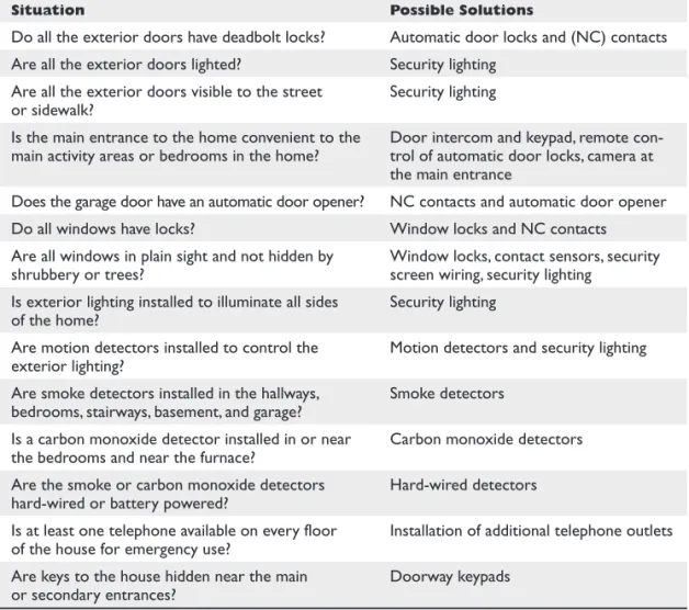
Based on the recommendations of the security services industry and several police and fire department checklists, the questions listed in Table 21-1 should provide the information you need to determine the must-haves and the could-haves of a home security system.
Interview the homeowners to identify how much interior and exterior detection and protection they desire. Review the floor plans and be sure to discuss the following items:
● Doors—all entry doors as well as and doors to separate areas of the house ● Windows and/or screens to be protected
● Interior motion sensor locations
● Fire protection—has an electrician installed it? Is it interfaced to security system?
Be sure to follow local codes
● Environment considerations—wine cellar, pool, spa, basement, low temperature
areas
● Keypads at main entry points, plus the master bedroom ● Exterior motion detection and actions
● Their desire to interface with home control of lighting and heating, ventilating,
air conditioning (HVAC)
In addition, be sure to discuss how many security access codes the homeowners would like and if they want to be able to secure a portion of the house while using the rest of it (this is called partitioning in security jargon). The results of this interview will help determine the security panel and components you will use.
Security System Technologies
In new construction situations, wired security systems are the first choice. They are easy to install during the pre-wire stage and are cost-effective over wireless technology components. However, wireless systems can be easily retrofitted into an existing home, though wiring is an option if the attic, crawlspace, and basement allow for retrofit wiring.
Other technologies, such as infrared (IR), ultrasonic, electromagnetic induction, and digital signal processors (DSP) are used in the sensors and detectors that can be incor-porated into the system. However, the most important consideration when designing a security system is the technology that is to be used to interconnect the components of the system, wired or wireless.
Security Zones
An important element in the design of a security system is the planning of the security zones and how the security system’s components are to be placed in each zone. A se-curity system zone includes the adjacent areas of a home that will be reported together when an alarm occurs. Each zone in a home can have a different number of doors and windows and can include different contents of the room or rooms. A security zone may be a single room, multiple rooms, open areas, or the exterior of the home.
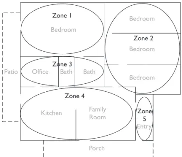
The zoning of a home should be based on the floor plan or layout of the home, the requirements of the homeowners, and the capabilities of the selected security system. For example, the zoning plan illustrated in Figure 21-1 creates five zones, each of which has different needs and requirements. Table 21-2 lists these five zones and their security needs.
Table 21-1
Situation Possible Solutions
Do all the exterior doors have deadbolt locks? Automatic door locks and (NC) contacts Are all the exterior doors lighted? Security lighting
Are all the exterior doors visible to the street
or sidewalk? Security lighting Is the main entrance to the home convenient to the
main activity areas or bedrooms in the home? Door intercom and keypad, remote con-trol of automatic door locks, camera at the main entrance
Does the garage door have an automatic door opener? NC contacts and automatic door opener Do all windows have locks? Window locks and NC contacts Are all windows in plain sight and not hidden by
shrubbery or trees? Window locks, contact sensors, security screen wiring, security lighting Is exterior lighting installed to illuminate all sides
of the home? Security lighting Are motion detectors installed to control the
exterior lighting? Motion detectors and security lighting Are smoke detectors installed in the hallways,
bedrooms, stairways, basement, and garage? Smoke detectors Is a carbon monoxide detector installed in or near
the bedrooms and near the furnace? Carbon monoxide detectors Are the smoke or carbon monoxide detectors
hard-wired or battery powered? Hard-wired detectors Is at least one telephone available on every floor
of the house for emergency use? Installation of additional telephone outlets Are keys to the house hidden near the main
or secondary entrances? Doorway keypads
P
A
R
T
Beyond the planning shown in Figure 21-1 and Table 21-2, additional information must be included, such as:
● Local fire safety laws and building codes require smoke detectors in all sleeping
areas, hallways, kitchens, and on each level of a home
● Four of the bedroom windows are located on the street side of the home ● The two doors leading to the patio and the family room door leading to the
porch are sliding glass doors
Security Component Planning
The owners of the home illustrated in Figure 21-1 have expressed a desire for the security system, when it’s enabled, to detect doors and windows being opened, glass breaking on street-side windows and sliding doors, a person entering through the main doorway or the home office, and a vehicle on the driveway. In addition, they are considering
Zone Rooms Outside Doors Windows Contents
1 Master bedroom 1 4 TV, jewelry, art 2 Bedrooms 0 6 TVs, collectibles
3 Office, baths 0 1 Computer, office equipment 4 Kitchen, family room 2 4 Microwave, appliances, home
entertainment center 5 Entry 1 2 Art
Table 21-2 The Zone Plan for the Layout Shown in Figure 21-1
Figure 21-1 An example of a zone layout plan diagram
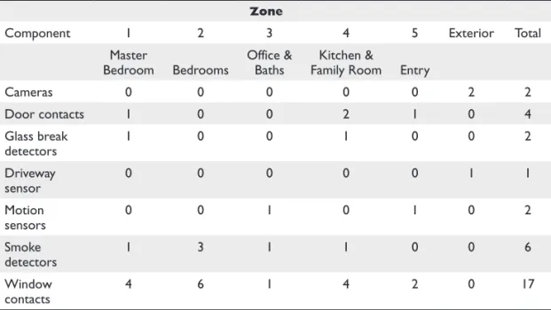
installing security cameras on the exterior of the home and security lighting on the front and street sides of the home. Table 21-3 summarizes the components required to provide this level of security by zone.
Defining the zones and sensors to be included helps you outline the specifications for selecting the security control panel. Most panels come with a standard number of zones, such as eight, and the panel can be expanded to add more zones. When design-ing which devices will be on what zones it is important to look at each of the device’s power requirements and the maximum power that can be supplied by the security panel. It may be necessary to add additional power sources to feed all of the powered devices. Consult the manufacturer’s documentation for details.
If the security system design includes either interior or exterior surveillance cameras or motion detectors, consider their placement carefully to ensure they can “see” the areas they are intended to view.
CROSS-REFERENCE See Chapter 19 for more on the functions and use of security system components and devices, and see Chapter 24 for more on video surveillance systems.
Security Systems and Structured Wiring
The next step in the design of the security system is to plan the cable requirements for the system. If the plan is to install homerun wiring to each of the security system com-ponents, the structured wiring plan must be adapted to include these cable runs.
Zone
Component 1 2 3 4 5 Exterior Total Master
Bedroom Bedrooms Office & Baths Family RoomKitchen & Entry
Cameras 0 0 0 0 0 2 2 Door contacts 1 0 0 2 1 0 4 Glass break detectors 1 0 0 1 0 0 2 Driveway sensor 0 0 0 0 0 1 1 Motion sensors 0 0 1 0 1 0 2 Smoke detectors 1 3 1 1 0 0 6 Window contacts 4 6 1 4 2 0 17
Table 21-3 Security System Component Planning
P
A
R
T
Security System Wiring
In a structured wiring environment, wiring is terminated at the security system’s master unit, or panel, from each sensor, keypad, contact, smoke or heat detector, or alarm sounding device. The wiring, like all structured wiring, is installed in a star topology with a homerun between the security system control panel and each device. Be sure to include the security wiring on the structured wiring chart or make a separate chart for it.
Hard-Wired Systems
The wiring installed to connect each component to the security system control unit should be homeruns between the security panel and each of the security devices. Loop-ing, that is, installing several devices such as window or screen contacts on a single loop of wire in series, should be minimized, if possible. Any security device that will be used to trigger the action of another home system device, such as a door contact or motion detector signaling a room’s lights be powered on, must be wired separately and individually.
Table 21-4 lists the more commonly used security system components and the wire type recommended for each device.
Security System
Component Wire Recommendation
Keypads Standard: 22 AWG 4-conductor stranded
Advanced, with voice pickup and playback: 2 runs of 18 AWG 2-conductor shielded stranded
Internal and external alarms, speakers, and sound devices
18 AWG 2-conductor copper wire AC power
connections 18 AWG 2-conductor copper wire Motion sensors,
glass-break detectors 22 AWG 4-conductor copper wire Door and window
contact sensors 22 AWG 2-conductor copper wire Fire alarm
connections, smoke detectors, and heat detectors
Fire power limited plenum (FPLP) cable or fire power limited (FPL) cable: 18 AWG 4-conductor copper wire
Ground connection 14 AWG 1-conductor copper wire
RJ-31x console 22 AWG 4-conductor copper wire minimum, Cat 5e preferred Wireless sensors Any of the sensors listed in this table but with radio frequency (RF)
communications and batteries to power them so no wiring is required Video monitors
and video capture devices
RG59 coaxial cable
Wireless Systems
Wireless security systems communicate with RF signaling that is typically in the range of 300 to 900 MHz. In many situations, a combination of wireless and wired devices may prove to be a more reliable design, depending on the distance from the wireless device to the base unit (range) or the necessity to install wireless devices to eliminate the need to pull wiring into the walls of a home. To ensure good perfor-mance, be sure to read and follow the specifications of the manufacturer’s products when installing wireless devices. Also be sure to note battery replacement is recom-mended annually.
RJ-31x Connections
If the security system is to include a telephone link, such as to the homeowner’s cell phone or a security monitoring service, for calling out when an alarm condition occurs, the design should consider whether a single phone line connection or multiple line connections are best for the home.
In the event of a security event (break-in, fire, and so on), the system can call out on a standard phone line or, by using an RJ-31x phone jack, it can seize the telephone line and hang up any phone call in progress, preventing any disruption from interfering with the automated telephone alert process.
Lighting Interfaced to the Security System
Security lighting has been proven to prevent intrusions, deter malicious activity, and enhance the aesthetics of a home. By interfacing with a home control system the lights can be programmed to go on when an alarm sounds, blink when a fire alarm sounds, and even turn on and off while the homeowners are away to make the house look oc-cupied. All of these events can be linked to the time of day so they only occur when it is dark. Many security systems today have some form of lighting control built into them for just these reasons and act as the home control system.
The design goal for a security lighting system should be to light the areas of a home’s exterior, especially those close to the home that would, without lighting, be shadowed or dark. Motion detectors can be used to turn on lighting around the home should movement be detected. These same outdoor motion sensors can also be set up to sound a simple chime inside the home to alert the occupants that some-one is outside.
When designing lighting control for security purposes, consider the following:
● Accent lighting Down lights, coach lights, landscape lighting ● Security lighting Flood lights
● Interior lighting Kitchen lights, living room lights, bedroom lights for
a “lived-in” look
Make a list of the lighting loads to be controlled and be sure to communicate with the electrician that these loads will be controlled by the security/home control system, so no timers or daylight sensors are needed.
P
A
R
T
The best way to provide good lighting and vision in exterior areas is to install me-dium intensity, nonglare lighting fixtures that are aimed downward or shielded. For exterior lighting, three types of lamps can be used:
● Halogen These are commonly used as floodlights or landscaping lights
because they provide a bright white or near-white light. Halogen lamps can be used to brightly light an area in connection with a motion detector sensing movement in its monitoring area.
● High-Intensity Discharge (HID) These lamps include mercury vapor, metal
halide, high-pressure sodium, and fluorescent lamps. With the exception of fluorescent lamps, HID lamps require a warm-up period before reaching their full brightness. For this reason, HID lamps should not be used in situations where the security system requires instant-on lighting. HID lamps are better used as general lighting to constantly light an area, such as landscape or accent lighting.
● Incandescent These high wattage lamps can be used in just about any security
lighting situation. However, because of their relatively limited life, they can be prone to burn out and defeat the purpose of the security lighting system if they are not properly maintained with a regular group replacement scheme.
If security lighting is being included in the security system design solely to provide lighting for exterior surveillance cameras, consider using cameras that include IR light-ing capabilities that allow the camera to virtually see in the dark.
Installing a Home Security System
A hard-wired security system requires very little after-installation maintenance. This type of security system provides the assurance that if a sensor or contact trips, the sys-tem master or control panel will receive a signal, which may not always be true of a wireless system. However, a wireless security system is easier to install in a retrofit situ-ation, although it also has some placement and operational issues that are discussed later in the chapter.
Component Wiring and Installation
Installing security system components as part of a new construction project allows the cabling required for the sensors, contacts, and keypads to be placed in a room or zone to be installed along with the structured wiring system. However, if the system is being installed in an existing home, wiring must be pulled through the existing walls, floor, or ceiling. Remember, the right wire type needs to be installed for each specific type of device.
The minimum wiring requirements for each of the more common security system components are detailed in the following sections.
Security System Control Panel
The system control panel, also referred to as an alarm system or a master unit, is where all the wiring of a security system’s sensors and contacts terminates. The system control panel should be placed in the same area as the structured wiring distribution panel or, if that is not possible, in a centrally located and convenient location that is not easily accessible from the outside (do not place it in the garage). A closet and the mechanical room are good locations.
The only specific electrical wiring required for the system control panel itself is access to an electrical outlet for the AC power transformer. The wire used should be 4-conductor 22-gauge copper cable from the control panel to the transformer.
Keypads
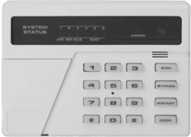
Security system keypads, like the one shown in Figure 21-2, can be wall-mounted or re-cessed units that provide a user interface to the security system to control a single zone or the whole-house system.
Security system keypads require a 4-conductor 22-gauge copper cable. Two of the wires carry power from the control panel to the keypad, and the other two wires are used to transmit signals between the keypad and the control panel.
Door and Window Contacts
Door and window contacts are passive switches and don’t require separate power from the system control panel. To connect a door or window contact to the control panel, use 2-conductor 22-gauge unshielded copper cable. Door and window contacts can be wired in series in a loop, with the wiring from the last contact looping back to the first contact. In this configuration, a signal from any of the contacts in the loop will be transmitted back to the control panel from the first unit in the loop. Figure 21-3 illus-trates how window contacts can be wired in series on a single loop of wire.
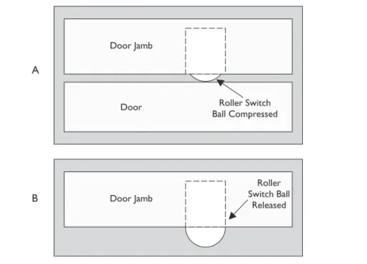
Door and window contacts are available in a variety of styles. The most commonly used styles include roller-ball styles, which operate by compressing and releasing a
Figure 21-2 A security system keypad is used to control the security settings of a zone.
Photo courtesy of Honeywell International, Inc.
P
A
R
T
roller-ball (as shown in Figure 21-4); recessed switches, which are inserted in holes drilled in the door or window and its framing (see Figure 21-5); surface-mount switches (see Figure 21-6).
Figure 21-6 shows how a surface-mount window contact works. When the window is closed, a magnet in the part mounted on the window closes the switch into its normal-ly closed (NC) position. When the window is opened, the magnet moves away from the spring-loaded switch inside the frame-mounted part and a trip signal is generated. A door contact operates in the same way; the only difference being that the magnet part moves away from the switch part when the door is opened.
To allow for a window to be open and still provide security protection, a second magnet can be mounted in the window frame to detect contact while the window is in the open position. This allows for the window to be in two positions, closed and open to this distance, and either location provides a NC contact.
Figure 21-3 Window and glass-break sensors wired in a series loop Figure 21-4 A roller-ball door and window contact switch
Glass-Break Sensors
The two common types of glass-break sensors are acoustic (sound) and vibration (shock). Which type is better for a particular installation depends on the type of glass (plate glass, tempered glass, or laminated glass) in the window, door, or relight pane.
Acoustic Glass-Break Detectors Acoustic detectors, also called active sen-sors, are tuned to pick up only the sound of breaking glass. This prevents them from generating a trip signal for any other sounds. Acoustic glass-break detectors are placed on a wall or ceiling near the windows to be monitored. Typically, a single acoustic sen-sor (see Figure 21-7) is able to monitor all the windows of a medium-sized room.
Figure 21-6 The operation of surface-mounted window contact switch A B
Figure 21-5 Part A of this illustration shows a recessed roller-ball contact sensor compressed when the door is closed. Part B shows that when the door is opened, the ball is released and an alarm event is triggered. P A R T V
One challenge to installing acoustic glass-break sensors is testing them. Instead of actually breaking a window to see if the sensor is working, several sensor manufactur-ers also sell glass-break detector testmanufactur-ers that make the sound of glass breaking—a much better way to test these units.
Acoustic sensors require power from the control panel plus two conductors for sig-naling; so 4-conductor 22-gauge copper wiring is required. If the sensor has a tamper-ing relay and the homeowner wishes to connect it to the control panel, six conductors are needed.
Vibration Glass-Break Detectors Vibration glass-break detectors, also called passive detectors, are place directly on the glass or on the window frame very close to the window. If an intruder knocks or taps on the glass or breaks it, the vibration is sensed and a trip signal is generated.
Vibration detectors (see Figure 21-8) are passive devices that don’t require power from the control panel. Two-conductor 22-gauge wire is used to connect the detector to the control panel.
When deciding the type of glass-break detector to install, be sure to consider if power is available to drive the acoustic sensors. When strategically placed, acoustic sensors can cover more than one window at a time, but with vibration detectors one should be installed on every window to be protected.
Motion Sensors
Two technologies are used in motion sensors: passive IR (PIR) or active ultrasound. Regardless of the technology used, the wiring requirements are the same. The most im-portant issue when installing a motion sensor is placement in the room. If the purpose of the sensor is to detect someone entering the room, the sensor cannot be placed so that an opening door blocks the sensor. The sensor should be placed so that it monitors the areas of a room where the homeowners have the most concern. The recommended height of a motion sensor is seven feet above the floor.
Figure 21-7 An acoustic glass-break detector “hears” the sound of breaking glass and triggers an alarm event.
A common cause of standard PIR motion detectors signaling false alarms is small children or household pets entering a room. Many PIR units are available with hori-zontal scan “pet alleys” that prevent movement by short or small children or pets from triggering an alarm. Adaptive units such as PIR/microwave sensors self-adjust to the room and its environment. Other sensors are designed to be pet-smart, with horizontal bands of the scan range set aside for pets and small children. Some units even attempt to estimate the weight of a scanned object and suppress the alarm for moving objects that are estimated to weigh less than 80 pounds.
Motion sensors, like the one shown in Figure 21-9, require a minimum of four conductors between the control panel and the sensor: two to carry 12V DC power from the control panel and two to carry the trip (motion-detected) signal. Some motion detectors also have additional contacts to detect attempts to tamper with the sensor and to report self-diagnostics to a control panel. Although these additional tamper monitoring terminals are generally not connected in home systems, if the homeowner wishes to include these functions in the security system, add two additional conductors in the cable to connect the sensor to the control panel.
Figure 21-8 A vibration glass-break detector is mounted on a windowpane to sense vibrations from knocks, taps, or hits on a window. Figure 21-9 A motion sensor detects movement in a space and creates an alarm event.
Photo courtesy of Honeywell International Inc.
P
A
R
T
Smoke, Fire, and CO Detectors
Smoke, fire, and carbon monoxide (CO) sensors are surface-mount devices that are installed on the ceiling or above doorways in hallways near bedrooms, kitchens (close to cooking areas), stairways, garages, mechanical rooms, and near furnaces and boilers.
Smoke, fire, and CO detectors require a 4-conductor 18-gauge unshielded fire-rated cable and can be wired in series (daisy-chained) with the wire terminating at the control panel connected to the first sensor, which is then wired to the second sensor, and so on. If more than five sensors are to be installed in series, they should be split up into sepa-rate series of four units to make troubleshooting easier, should it be necessary later.
Photoelectric Beam Devices
There are locations in a home where a passive infrared (PIR) device just isn’t practical. For many of these situations, a photoelectric device may be used instead. This tech-nology is commonly used in smoke detectors, where a beam of light is used to detect smoke entering its testing chamber. If smoke interrupts the light beam, an alarm event is generated (typically sounding a shrill screeching sound). However, a photoelectric device can also be used inside windows, doors, and skylights (including outdoors) using the same basic principle of PIR and the photoelectric beam in the smoke alarm. If the light beam is interrupted, an alarm is generated. Newer developments in photo-electric detection devices employ two, four, and even six beams across a space as wide as 44 inches.
Sirens
Most residential security systems use what are called speaker sirens. The siren (sound-ing) unit is a module located in the security system control panel that is connected to the siren speaker using 2-conductor 18-gauge copper cable. The siren speaker is a pas-sive device that doesn’t require power, much like a standard audio speaker. However, it does require a heavier gauge cable than the sensors so that the sound signal is not lost as it travels over the cable.
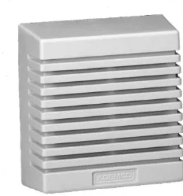
Speaker sirens are available in two general styles: horn or surface-mount. Horn-style speaker sirens are typically used for exterior applications or placed in an out-of-the-way location, like an attic or a garage. Surface-mount speakers (see Figure 21-10) are like small audio speakers that can be mounted in a room or another interior location.
Low Temperature Sensors
There are two types of low-temperature sensors: those that have a mechanical switch, also called a freezestat, and those that use a length of tubing that acts as an averaging sensor. In either case, when the temperature falls below a certain level, for example 39 degrees Fahrenheit or 41 degrees Fahrenheit (both common settings), the sensor sounds an audible signal if desired and transmits a signal to a security system control-ler. Some devices are hardwired and send signals through a relay, and others connect using an RJ-12 connection to structured wiring.
Water Detectors
These types of sensors or detectors are also called leak detectors because they detect water leaks. They do this by monitoring for water pooling in a certain area or any detectable change in the water pressure in a pipe or tube. Nearly all water detector sensors can be connected to a home security network through either an interface module or via a relay connection on the sensor.
Humidity Sensors
Humidity sensors monitor the moisture content of the air inside a home or enclosed area. Most of the better humidity sensors have both a high and low setting that signal when the humidity gets too low or too high. Other humidity sensors have only a single set point and either signals when the humidity is too low or too high, but not both. Those humidity sensors that can be interfaced to a home security control system are able to connect to any system that recognizes relay signals or dry contact switches, such as power line communication (PLC) and other power line technologies.
Telephone Interface Connections
Most security control panels have a relay connection that is used to seize a telephone line to transmit an alarm signal, message, or voice recording to a home security moni-toring service or telephone numbers programmed in the system.
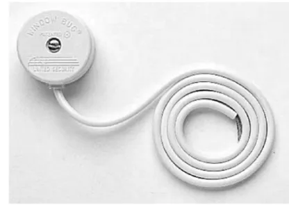
The security system control panel should be the first device on the telephone wir-ing in the home. This means that the RJ-31x jack on the control panel or an add-on telephone module (see Figure 21-11) should be connected directly from the network interface device (NID) and before the telephone distribution module of the structured wiring system. The wiring from the NID to the security control panel and between the security control panel and the telephone system panel should be Cat 5e cable.
Figure 21-10 A surface-mounted speaker siren
Photo courtesy of Ademco.
P
A
R
T
Configuring the Security System Control Panel
The detailed steps used to configure the security system control panel for a home security system vary by manufacturer. Most systems have a proprietary configura-tion process that is tied to the particular modules that are included in the standard configuration of the control panel. When installing and configuring a home security system control panel, follow the manufacturer’s documentation to set up and con-figure the system.
Perform an interview with the homeowner about the security system to get the infor-mation necessary for system setup and user codes. Using the worksheets usually provid-ed by the manufacturer, identify any further information requirprovid-ed. You can complete much of this information prior to the interview, so just get the homeowner’s approval and a few more details to help speed the process along.
When setting up an alarm system, the modules and functions that usually must be configured to ensure the proper operation of the security system are
● Hardware and devices
● Control panel install and power up ● Telephone connection
● Keypad hookups ● Sensor interfaces ● Fire alarm interfaces ● Sounder outputs
● Programming and configuration (where applicable) ● Zone type setups
● User codes and setups ● Entry/exit delays ● Panic modes
● Digital communicator setup
Figure 21-11 A telephone interface module with RJ-31x jacks
● Alarm verification process setup ● Home control setups
● Remote telephone control
Again, be sure to follow the specifics for setup outlined in the manufacturer’s docu-mentation.
Home Security System Testing
The installation of a home security system isn’t finished until the entire system has been completely tested and any necessary adjustments are made and retested. The test-ing process essentially boils down to triggertest-ing trip alerts on each installed component of the system. This means that every sensor, contact, and detector must be tested by forcing the condition it was installed to monitor: opening windows and doors and entering rooms or areas outside the home monitored by motion detectors. The com-plete security system should be tested, including any video surveillance (Chapter 24) or home access (Chapter 20) systems that are installed and attached to the security system control panel.
The testing should start with the testing of the components in each of the rooms in a single zone. After one zone is completely tested, proceed to the next zone. It is recom-mended that the first room and zone tested should be the one nearest the security system control panel. Be sure to use a zone list or wire chart to check off every device tested.
Cable Tests
During pre-wire or prior to device installation be sure to conduct cable or wire testing. You should perform the standard structured wiring cable tests, including continuity and impedance. This should be done at pre-wire so as to catch any problems that can easily be remedied while the walls are open. Testing can also be done at trim-out prior to the installation of devices to confirm all the wiring is good and if a problem exists, it would be with the devices being installed.
CROSS-REFERENCE Chapter 3 covers testing procedures for wiring.
Detector Tests
After installation, hookup, and setup programming of all devices, perform the follow-ing testfollow-ing steps in each room:
1. Set the exit timer to its lowest setting. Security systems usually have at least two settings that allow a variable amount of time before the system arms or disarms to give the homeowners time to enter the home and disarm the system or exit the home after arming the system.
P
A
R
T
2. Centrally arm the system as it will be when the homeowners leave the home.
3. Allow the exit delay time to lapse.
4. Open each protected door and window or enter a space monitored by a motion sensor to cause a trip signal and verify the alarm is triggered.
5. Also test each smoke and CO sensor located in each room or zone by pressing the test button on each. If the expected alarm isn’t activated, continue to troubleshoot and test the sensor, control panel, and the alarm until all three are working properly, then move onto the next sensor.
6. On most systems, you’ll need to reset the system after testing each contact, sensor, or zone.
7. After completing the testing in all zones, repeat the testing, with the customer observing, on at least one sensor in each zone.
8. Remember to reset the exit time setting to the desired time before leaving. After completing the detector testing, test all of the user codes and any other unique system setup areas. Finally, orient the customer to the system and train the customer on the system’s normal operations.
Documentation on how to use the security system should be given to the homeowners for reference. Documentation of the security wiring and zones should be kept in the security control panel. Documentation of the system setup should also be given to the homeowner for safekeeping away from the panel and not readily accessible to others. Finally, in your project folder, be sure to keep documentation of the security system setup, programming, testing, digital communicator, and ongoing maintenance and ser-vice of the system.
Security and Fire Alarm Testing Regulations
In addition to the home security industry’s guidelines, many countries, states and provinces, counties, and cities have regulations or guidelines on how frequently a home security system must be tested. Ensure the customer is aware of the regulations and guidelines. Testing guidelines for home security systems are developed and published by the National Fire Protection Agency (NFPA), Security Industry Association (SIA), Underwriters Laboratories (UL), American National Standards Institute (ANSI), Canadian Standards Association (CSA), and the National Burglar and Fire Alarms Association (NBFAA), as well as standards organizations, and police and fire associations around the world.
Table 21-5 lists testing frequencies of monitored and unmonitored control panel com-ponents. A monitored component is one that the control panel has circuitry to monitor and display an alert should the component begin to fail, even intermittently. Unmoni-tored components are those for which a failure is not alerted. For example, a security keypad near a back door of a home may be an unmonitored component of a security system. If the keypad malfunctions, the homeowner knows the device should be repaired or replaced, but the security system may not display a notice or signal the component fail-ure. However, the security system should alert the homeowner if a monitored component such as a door contact or a motion sensor fails to respond to monitoring signals.
Also explain to the homeowners that they should review the alarm ordinance in effect in their city, county, or state or province, and that they may be required to get a permit or license for their home security system before it will be recognized as a legal system by that authority. As a billable service to your clients, you may identify this in-formation and process the necessary paperwork for them.
Chapter Review
An important element in the design of a security system is planning the security zones and how the security system’s components are to be placed in each zone. A security zone may be a single room, multiple rooms, open areas, or the exterior of the home. The zoning of a home should be based on the floor plan or layout of the home and the requirements of the homeowners.
The design of the security system should include a plan for the system’s cable require-ments. Structured wiring is installed in a star topology with a homerun from the security system master unit to each device. Wireless security systems communicate with RF sig-naling. A combination of wireless and wired devices may prove to be more reliable.
If the security system is to include an RJ-31x jack to provide the system with a tele-phone link, the system will have the capability to seize a teletele-phone line to place an automated telephone alert.
Security lighting has been proven to prevent intrusions, to deter malicious activity, and to enhance the aesthetics of a home. The design goal should be to light areas along a home’s exterior that are in the shadows or dark. Motion detectors can be used to turn on lighting around the home should movement be detected. In addition, lighting should be identified and controlled to give the home the “lived-in” look.
Installing security system components as part of a new construction project allows the cabling required for the sensors, contacts, and keypads to be placed in a room or zone to be installed along with, or as part of, the structured wiring system. If the system is installed in an existing home, wiring must be pulled through the existing walls, floor, or ceiling.
The system control panel terminates the wiring from all sensors or contacts. The system control panel should be placed in the same area as the structured wiring distri-bution panel or a protected area; not in the garage. The system control panel usually requires electrical wiring to an AC outlet for the plug-in power transformer.
System Component Testing Frequency
Monitored control panel components Annually Unmonitored control panel components Semiannually Control panel diagnostic services Annually Control panel/telephone interface Annually Smoke and CO detectors Annually Door and window sensors Annually Sirens, sounding devices, and strobe lights Annually
Table 21-5 Recommended Security System Testing Frequencies P A R T V
Door and window contacts are passive switches and don’t require separate power from the system control panel. Door and window contacts are available in a variety of styles, including recessed switches, surface-mount switches, and roller-ball styles.
The two common types of glass-break sensors are acoustic and vibration. The type that should be used for a particular installation depends on the type of glass used. Acoustic detectors are tuned to pick up only the sound of breaking glass in a medium-sized room. Vibration glass-break detectors are placed directly on the glass or the win-dow frame of every winwin-dow being protected.
Security system keypads are wall-mounted or recessed units that provide user inter-face to the security system to control a single zone or the whole-house system.
Motion sensors are either passive IR (PIR) or active ultrasound. The recommended height of a motion sensor is seven feet above the floor.
Most residential security systems use speaker sirens that are activated by the control panel sending audio signals. Speaker sirens have two styles, horn or surface-mount.
Smoke, fire, and carbon monoxide (CO) sensors are surface-mount devices installed on ceilings or above doorways in hallways near bedrooms, kitchens (close to cooking areas), stairways, garages, and near furnaces and boilers. Smoke and fire detectors must be installed with fire-rated wiring.
Environmental monitoring sensors, which include low temperature sensors, water or moisture detectors, and humidity sensors, can be integrated into a security system to prevent conditions from harming the home or its contents.
Security control panels use a relay connection inside an RJ-31x telephone jack to seize a telephone line and transmit an alarm signal, message, or voice recording to a home security monitoring service or programmed phone numbers. The security system control panel should be the first device on the telephone system.
The process and detailed steps used to configure the security system control panel for a home security system varies by manufacturer, and a proprietary configuration process is used to configure the control panel. When installing and configuring a home security system control panel, follow the manufacturer’s documentation to set up and configure the system.
The installation of a home security system can be considered finished when the entire system has been completely tested and any necessary adjustments are made and retested. The testing process involves triggering trip alerts on each installed component of the system. Testing should begin with cable or wire testing and continue by testing the sensors and contacts in each room or zone. Documentation should be done of wiring and zones and kept inside the security panel. Documentation of setup should be given to the homeowner for safekeeping, and all documentation should be kept in the installation company’s project folder.
Many countries, states and provinces, counties, and cities have regulations or guidelines concerning the frequency for home security system testing. Homeowners should be made aware of any alarm ordinances in effect in their city, county, or state or province.
Questions
1. In a home security system, where do homeruns to zone sensors and contacts terminate?
A. Security system control panel
B. Home automation controller
C. Keypad
D. Wiring distribution panel
2. Which type of glass-break sensor is typically mounted directly to the glass of a window or door?
A. Acoustic
B. Vibration
C. PIR
D. All of the above
3. At what height should a wall-mounted motion detector be installed?
A. Four feet
B. Five feet
C. Seven feet
D. It should be even with light switches and keypads.
4. On some sensors, there are tamper sensors and self-diagnostic relays. When these options are wired, what wire/cable should be used to completely wire a motion sensor?
A. 4-conductor 22-gauge unshielded copper wire
B. Two runs of 4-conductor 22-gauge unshielded copper wire
C. Cat 5e
D. None of the above; motion sensors are passive devices.
5. Which of the following is not a recommended location for a smoke detector?
A. Bedrooms
B. Hallways near bedrooms
C. Kitchen D. Bathroom P A R T V
6. What connector type is used to connect a security system control panel to a telephone interface? A. RJ-11 B. RJ-21x C. RJ-31x D. RJ-45
7. Which of the following security system elements should be checked and tested at least semiannually?
A. Monitored control panel components
B. Unmonitored control panel components
C. Smoke and CO detectors
D. Door and window sensors
8. Which type of security system sensors or contacts can be wired in series on a loop?
A. Door contacts
B. Window or screen contacts
C. Cameras
D. Motion sensors
9. In general, what is the recommended cabling for window and door contacts and sensors in a home security system?
A. 14 AWG 1-conductor copper wire
B. 22 AWG 2-conductor copper wire
C. Cat 5e
D. RG6
10. Which of the following lamp types is/are commonly used for brightly illuminating the exterior area in a security lighting system?
A. Halogen
B. HID
C. Incandescent
D. IR
Answers
1. A. The homerun wiring of the security system could be routed through the structured wiring distribution panel or the home automation controller, but this approach would complicate the home’s wiring unnecessarily. Keypads only serve as user interfaces and zone controls in a security system.
2. B. PIR is not a type of glass-break sensor, and acoustic sensors are typically mounted where they can listen to and monitor all of the windows in a room.
3. C. This height allows the sensor to scan the full-height of any person entering or occupying a room.
4. B. Six conductors are required to complete the wiring of a sensor with tamper detection.
5. D. It is not necessary to install a smoke detector here. The other choices are locations where a smoke detector should be installed.
6. C. A telephone interface module with an RJ-31x jack facilitates line seizure and the ability to place a security alert on a telephone line.
7. B. The other security system components should be tested annually.
8. B. Window or screen sensors can be wired in a series-connected loop. All other security system devices should be wired in parallel with individual homeruns.
9. B. These devices require only 2-conductor wire.
10. A, B, and C. IR lighting is used to allow security cameras to see in the dark, but it won’t work to light up the exterior area of a home.
P
A
R
T