Best Practice Guide to Cable
Ladder and Cable Tray Systems
Channel Support Systems and other Associated Supports
BEAMA Best Practice Guide to Cable Ladder and
Cable Tray Systems Including Channel Support
Systems and other Associated Supports
Contents
INTRODUCTION 5
DEFINITIONS AND ABBREVIATIONS 6
1. Packing Handling and Storage 8
1.1 General Packing and Handling 8
1.2 Loading and offloading recommendations 9
1.3 Storage 11
2A. Installation of the system 12
2.1 Common tools for Installation 12
2.2 Structural characteristics 12
2.3 Support Systems 18
2.4 Straight cable ladder and cable tray lengths 29
2.5 Coupler types (refer to manufacturer’s literature) 32
2.6 Fixings 36
2.7 Fittings 36
2.8 Accessories 39
2.9 Site modification 39
2.10 Earth protection and EMC 40
2B. Installation of Cable 41 2.11 Preparation 41 2.12 Wiring Regulations 41 2.13 Power Cables 41 2.14 Data Cables 46 2.15 Expansion 46
2.16 Electro Mechanical Effects 46
3. Environment 48
3.1 Selecting the right material and finish 48
3.2 Finishes 56
3.3 Non-Metallic systems 61
3.4 Loadings 63
3.5 Temperature 65
4. Health & Safety 67
5. Maintenance 68 5.1 Inspection 68 5.2 Removal of cables 68 5.3 On site repairs 68 6. Sustainability 69 6.1 Sustainable development 69 6.2 REACH regulations 69
6.3 The management of WEEE and RoHS 69
6.4 Environmental footprint 70
7. Applicable Standards 71
FIGURES
Figure 1: Methods of removal 9
Figure 2: Loaded beams 13
Figure 3: Channel Support Systems 20
Figure 4: Use of Brackets with channel 20
Figure 5: Typical types of Base Plates 21
Figure 6: Beam clamps 22
Figure 7: Channel type cantilever arms 23
Figure 8: Trapeze hangers using channel 23
Figure 9: Trapeze hangers other than using channel 25
Figure 10: General installation with ladder 26
Figure 11: Threaded rod suspension brackets 26
Figure 12: Wall support brackets 27
Figure 13: Overhead hanger 28
Figure 14: Hold down brackets and clips 28
Figure 15: Schematics of the SWL Type tests I – IV for cable ladder and cable tray 30
Figure 16: Expansion couplers 32
Figure 17: Typical Expansion Coupler Location 33
Figure 18: Typical graph for determining the expansion coupler setting gap 34
Figure 19: Bendable couplers 35
Figure 20: Vertical hinged couplers 35
Figure 21: Horizontal hinged couplers 36
Figure 22: Support locations for cable ladder fittings and cable tray fittings 38
Figure 23: Cable guides for pulling cables 42
Figure 24: Cable pulling tools 44
Figure 25: Cable fastening devices 45
Figure 26: Galvanic Series Chart 50
TABLES
Table 1: Minimum internal bending radii of bends in cables for fixed wiring 43 Table 2: Spacings of supports for cables in accessible positions 45 Table 3: Limiting electrical potential differences to minimise corrosion effects 50 Table 4: Description of typical atmospheric environments related to the estimation
of corrosivity categories 52
Table 5: Life to first maintenance for a selection of zinc coating systems in a range
of corrosivity categories 54
Table 6: Steel and zinc coating thickness 56
Introduction
This publication is intended as a practical guide for the proper and safe* installation of cable ladder systems, cable tray systems, channel support systems and associated supports. Cable ladder systems and cable tray systems shall be manufactured in accordance with BS EN 61537, channel support systems shall be manufactured in accordance with BS 6946.
It is recommended that the work described be performed by a competent person(s) familiar with standard electrical installation practices, electrical equipment, and safety of electrical wiring systems.
These guidelines will be particularly useful for the design, specification, procurement, installation and maintenance of these systems.
Cable ladder systems and cable tray systems are designed for use as supports for cables and not as enclosures giving full mechanical protection. They are not intended to be used as ladders, walk ways or support for people as this can cause personal injury and also damage the system and any installed cables.
* Safe use of these products is best ensured by installing parts that have been designed and tested together as a system.
This guide covers cable ladder systems, cable tray systems, channel support systems and associated supports intended for the support and accommodation of cables and possibly other electrical equipment in electrical and/or communication systems installations. This guide does not apply to conduit systems, cable trunking systems and cable ducting systems or any current-carrying parts.
BEAMA Best Practice Guide to Cable Ladder
and Cable Tray Systems Including Channel
Support Systems and other Associated Supports
DISCLAIMER
This publication is subject to the copyright of BEAMA Ltd. While the information herein has been compiled in good faith, no warranty is given or should be implied for its use and BEAMA hereby disclaims any liability that may arise from its use to the fullest extent permitted under applicable law.
©BEAMA Ltd 2012
Copyright and all other intellectual property rights in this document are the property of BEAMA Ltd. Any party wishing to copy, reproduce or transmit this document or the information contained within it in any form, whether paper, electronic or otherwise should contact BEAMA Ltd to seek permission to do so.
6
Definitions and Abbreviations
Accessory Component used for a supplementary function e.g. to join two components together, clamp or fix to walls, ceilings or other supports, covers and cable retainers
Associated supports Bespoke supports for cable tray and cable ladder other than BS 6946 channel supports
Cable cleats Used within an electrical installation to restrain cables in a manner that can withstand the forces they generate, including those generated during a short circuit.
Cable ladder System component used for cable support consisting of supporting side members, fixed to each other by means of rungs
Cable ladder system Assembly of cable supports consisting of cable ladder lengths and other system components
Cable ties Is a type of fastener, especially used for binding and organising several cables or wires together or to a cable management system
Cable tray System component used for cable support consisting of a base with integrated side members or a base connected to side members Note: cable tray includes perforated tray and wire mesh
Cable tray system Assembly of cable supports consisting of cable tray lengths and other system components
Channel support systems A light structural support system usually consisting of steel channel section (strut), steel brackets, channel nuts and set screws
Note: channel support systems comply with BS 6946
Coefficient of linear The change in length per unit length per unit rise in temperature expressed
expansion in degrees C-1.
Competent person Person who possesses sufficient technical knowledge, relevant practical skills and experience for the nature of the work undertaken and is able at all times to prevent danger and, where appropriate, injury to him/herself and others
Damage With relation to cable management can be represented by broken
welds, severely deformed / buckled sections
Deflection The elastic movement of the section as a result of imposed loading Eccentric loads A load imposed on a structural member at some point other than the
centroid of the section
Electrical continuity The ability of a system to conduct electricity within prescribed impedance limits
7 Electromagnetic compatibility A system’s ability to neither radiate nor conduct electromagnetic
energy in such a manner as to cause unwanted effects
Equipotential bonding Electrical connection maintaining various exposed-conductive-parts and extraneous-conductive-parts at substantially the same potential
Fitting System component used to join, change direction, change
dimension or terminate cable tray lengths or cable ladder lengths
Fixings Nuts, bolts, washers etc
(Internal fixings are used for connecting system components together as recommended and supplied by the cable support system manufacturer) (External fixings are used for connecting system components to an external structure and are not normally supplied by the cable support system manufacturer)
HDG finish Steel hot dip galvanized after the product is manufactured
Imposed load Any load other than the weight of the structure itself. (Imposed
loads can include electrical cables and equipment, wind, ice and snow)
MICC (cable) Mineral insulated copper clad
Non-metallic System which consists of uPVC (Unplasticised Polyvinyl Chloride)
or GRP (Glass Reinforced Polymer)
PG finish Steel pre-galvanized before the product is manufactured
Point load A concentrated load at a single point
Safe working pull out load The maximum allowable load on a channel nut connection when applied perpendicularly to the strut length
(BS 6946:1988 Requirements for safe pull out loads – the test failure load shall be a minimum of three times the safe working pull out load)
Safe working slip load The maximum allowable load on a channel nut connection when applied parallel to the strut length
(BS 6946:1988 Requirements for safe working slip – the test load required to give continuous slip shall not be less than three times the safe working slip load.)
Span Distance between the centres of two adjacent support devices
SWL (safe working load) Maximum load that can be applied safely in normal use UDL (Uniformly Distributed Load) Load applied evenly over a given area
1.1 General Packing and Handling
1.1.1 Straight lengths of trays, ladders, covers and channel
These shall be packed in bundles using adequate banding* and balanced at the centre. * It is recommended that where possible non-metallic banding is used in order to avoid rust stains forming on galvanized products and contamination of stainless steel products.
Where products of five metre lengths or above are packed in bundles, they shall be supported with a minimum of three timber bearers which provide sufficient clearance to accommodate the forks of a forklift truck. Bearers shall be spaced evenly along the length of the bundle.
Where shorter length products are packed in bundles, they shall be supported with a minimum of two timber bearers which provide sufficient clearance to accommodate the forks of a forklift truck. Bearers shall be spaced evenly along the length of the bundle. Bundles should be placed on a flat level surface with timber bearers. If bundles are stacked on top of one another they should be aligned vertically. The handler is responsible for ensuring that the stack is stable. The working height and load capacity of the storage facility and/or transport vehicle should not be exceeded.
1.1.2 Boxed and bagged parts
Boxes and bags should be stacked onto suitably sized pallets for handling by a fork lift truck.
Pallets of parts must be kept dry and stacking should be avoided. 1.1.3 Tray and Ladder Fittings
Small parts should be stacked onto suitably sized pallets for handling by a forklift truck. Each pallet should be suitably wrapped in order to secure the parts. Pallets of parts must be kept dry and stacking should be avoided.
Large parts should be packed and transported in the same way as straight lengths detailed above.
1.1.4 Specialised Packaging
Where delivery involves transhipment or rough handling en route it is recommended that products are packed in wooden crates or wooden cases.
SECTION 1
1.2 Loading and offloading recommendations
Site deliveries should preferably only be made where suitable mechanical handling equipment is available on site.
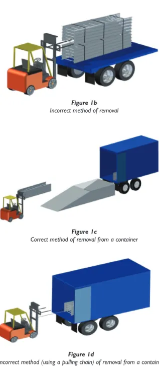
The delivered material must be treated with care. Lifting must only be carried out from the sides and the forklift truck tines must pass below a complete bundle, see Figure 1a. Tines must never*be inserted into the end of the bundle, see Figure 1b unless provision is made such as special packaging and/or extended tines, otherwise the safety limits of the lifting vehicle may be exceeded and damage may be caused to the equipment being lifted.
For offloading by crane suitable lifting beams should be inserted from side to side beneath a bundle and these must be sufficiently long to avoid undue pressure on the edges of the bottom components.
The tensioned banding used for securing bundles of equipment during transport is not suitable for lifting purposes. When cutting this banding appropriate eye protection must be worn to avoid injury.
Sheared steel (particularly pre-galvanized or stainless steel) does have relatively sharp edges and protective gloves must be worn during handling.
*Except when utilising extended forks and specialised packaging Figure 1a
Correct method of removal
Figures 1 Methods of removal
Figure 1b Incorrect method of removal
Figure 1c
Correct method of removal from a container
Figure 1d
Incorrect method (using a pulling chain) of removal from a container Figures 1
Methods of removal
For shipment using containerisation special provision should be made for example a ramp which allows access for lifting by forklift from one end or both ends, see Figures 1c and 1d.
1.3 Storage
In order to store Cable Tray Systems, Cable Ladder Systems, Channel Support Systems and other supports safely and maintaining them in their delivered condition, the following guidelines should be
considered:-Products which are either Hot Dip Galvanized (HDG) after manufacture, stainless steel or non-metallic can be stored outside without cover (excluding boxed items). When stored outside products should be stacked in a method that ensures adequate drainage. However outside storage is not recommended for galvanized products due to wet storage stain (see below). Ideally, all metallic products should be stored undercover in a dry, unheated environment and be loosely stacked off the ground to ensure adequate ventilation. It is important that products that have different finishes are kept apart. Products Pre Galvanized (PG) before manufacture should always be protected and stored in a well ventilated and dry location, and stacked as above.
Any components packaged in degradable bags, boxes, cartons etc. should always be stored in a well ventilated and dry location.
All products should be stored away from areas where processes or activities could cause damage and/or contamination. Due consideration should be given to ensure products are stacked together by type and width and in such a way as to prevent toppling. 1.3.1 Wet Storage Stain
If galvanized products are allowed to become wet whilst stacked awaiting transportation or installation the finish may quickly suffer from unsightly staining and powdering on the surface. This is commonly known as ‘wet storage stain’ and detracts from the overall appearance of the product. Generally this condition does not however, reduce the life expectancy of the corrosion resistance of the finish.
Where equipment has been affected by wet storage stain the unsightly marking will usually become much less prominent and will often disappear completely within months of installation. The stain is converted to zinc carbonate by reaction with atmospheric CO2so providing a protective patina.
The following recommendations are intended to be a practical guide to ensure the safe and proper installation of cable ladder and cable tray systems and channel support and other support systems. These guidelines are not intended to cover all details or variations in cable ladder and cable tray installation and do not provide for every installation contingency.
It is recommended that the work described in the following section is carried out by competent persons who are familiar with the products being installed and the safety standards associated with them.
2.1 Common tools for Installation
The following tools are commonly used for installation of cable management systems:
2.2 Structural characteristics
When considering the installation of the cable supports system it is imperative to avoid the cutting or drilling of structural building members without the approval of the project leader on site.
Cable ladders, cable trays and their supports should be strong enough to meet the load requirements of the cable management system including cables and any future cable additions and any other additional loads applied to the system.
Support systems can be broken down into a number of elements or components. To design a safe system it is necessary to check each element in turn to ensure:
•
that it can safely support the loads being imposed upon it, and•
that the proposed fixings to adjacent components are also sufficient for the intended load and•
that any declared deflection limits are not exceeded.SECTION 2A
Installation of the system
Metal Cutting Saw/Grinder Touch Up Material Screwdrivers Drill with Bits Files Spanners
Appropriate Safety Equipment (PPE)
Levelling Device Tape Measure Set Square G Clamps Torque Wrench
Consult the manufacturer for any further assistance on system design.
On many occasions cable ladder or cable tray is installed in circumstances where it will only ever carry a light cable load, possibly just one or two cables, and its main role is to physically secure and protect its contents. In these situations it is often the inherent ruggedness or the aesthetics of the cable ladder or cable tray design which bear most heavily on the specification decision. However, when a support system is required to be more heavily loaded it is useful to have knowledge of the theoretical aspects of rudimentary structural design in order to ensure that the completed system does fulfil its purpose with the greatest safety and economy.
2.2.1 Beams
Any installed cable ladder, cable tray or channel support system can be considered structurally as a loaded beam (Figures 2); four basic beam configurations may be found in a typical installation:
•
Simply supported beam•
Fixed beam•
Continuous beam•
Cantilever2.2.1.1 Simply supported beam
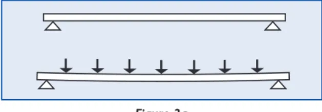
A single length of cable ladder, cable tray or channel mounted on, but not restrained by two supports, represents a simply supported beam (Figure 2a), which will bend as any load is applied to it with the supports offering no restraint to this bending.
Figure 2a Simply supported beam
Figures 2 Loaded beams
This simple beam arrangement is fairly onerous and does not realistically model many real life installations; thus the load/deflection information given in this guide is based upon more typical multi-span configurations, which also incorporate joints. However, if an un-jointed single span does actually occur the Safe Working Load can, as a practical guide, be taken as 0.5 of that indicated by the manufacturer’s multi-span loading details.
The introduction of a mid-span joint (Figure 2b) into a simple beam arrangement makes analysis far more complex. This arrangement represents the most testing situation for a cable ladder, cable tray or channel support joint. For this configuration the manufacturer should be consulted for the safe working load.
2.2.1.2 Fixed beam
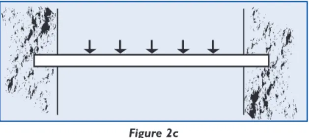
A fixed beam arrangement (Figure 2c) is a single structural member with both ends fastened rigidly to supports. Compared with a simple beam this degree of restraint does significantly increase the ability of the beam to carry loads but it is unlikely that cable ladder or cable tray can, in practice, be secured sufficiently rigidly to be considered as a fixed beam.
However, in the context of a complete cable ladder or cable tray system the main importance of the fixed beam configuration is that some appreciation of its properties, along with those of a simple beam arrangement, will assist the designer to understand the more complex behaviour of a continuous, multispan cable tray installation.
Figure 2b Mid-span joint
Figure 2c Fixed beam arrangement Figures 2
2.2.1.3 Continuous beam
A typical multi-span cable ladder or cable tray installation behaves largely as a continuous beam and the greater the number of spans the closer the similarity. However in practice a run must contain joints and it can also never be considered of infinite length so it is important to appreciate how its characteristics do vary from span to span and how these variations should be taken into account when designing the installation.
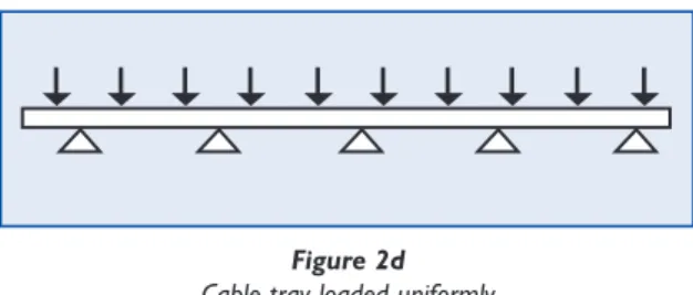
When a run of cable tray is loaded uniformly (Figure 2d) from end to end the load on each span is effectively in balance with the loads on the adjacent spans.
This causes the inner spans to behave substantially as fixed beams imparting to them a considerable load carrying ability. However the end spans (Figure 2e) of the installation are not so counterbalanced, thus they perform more akin to simple beams, with consequently lower load carrying capabilities.
Because of this it may be necessary to reduce the end span to less than the intermediate span length. The need for this depends on the ladder/tray manufacturer’s recommendations, which should be based on load tests carried out to BS EN 61537. See section 2.4 Installation of straight cable ladder and cable tray lengths for further details.
2.2.1.4 Cantilever beam
This type of arrangement most commonly occurs with the brackets which are used to
NO COUNTER-BALANCE COUNTER-BALANCE INNER SPAN END SPAN Figure 2e
End spans not so counterbalanced
Figures 2 Loaded beams
Figure 2d Cable tray loaded uniformly
support cable ladder or cable tray, these being fixed to the structure at one end only. For cable ladder or cable tray installations it is usual to consider the cable load to be uniformly distributed along the length of the cantilever arm (i.e. across the width of the ladder or tray); however, if cables will be bunched then their combined weight effectively acts as a point load on the arm so the bunch should be laid nearest the supported inner end (Figure 2f).
Consult manufacturers for safe working loads on cantilever arms. Manufacturers may supply safe working loads for both uniformly distributed loads and point loads at the ends of the cantilever arms.
2.2.2 Columns
Any vertically orientated component, whether cable ladder, cable tray or support, acts structurally as a column; it is not usual to consider cable ladder or cable tray in this way because they are not designed for this purpose.
Supports are however, frequently used as vertical columns.
The downward load which can be applied to the end of a column is proportional to the column length and the compressive strength of the material from which it is made. However there are few real applications where no loads are applied from other directions and since the effects of such loads are very significant it is important to consider the totality of the intended structure rather than focus simply only on the loads applied down the column.
Proper structural analysis must take detailed account of any side forces or eccentric loads caused by cantilever arms or other brackets fixed to the vertical channel. Such calculations must be carried out by a competent person such as a structural engineer. Consult the manufacturer for safe loading data for supports used as columns.
Figure 2f
Bunch laid nearest the support inner-end Figures 2
2.2.3 Deflection
All beams will deflect (Figure 2g) when a load is imposed. The magnitude of the deflection depends upon the following factors:
•
The load on the beam,•
The load type – UDL (uniformly distributed load) or point load,•
The distance between the beam supports (span),•
How the beam is fixed and supported,•
The size of the beam,•
The material of the beam.A beam’s stiffness is derived from its cross sectional shape (defined by its ‘Moment of Inertia or ‘I’ Value’), and the stiffness of the material from which it is made (defined by its” Modulus of elasticity or ‘E’ value’). The greater the ‘I’ value of beam and the greater the ‘E’ value of its material, the greater the beam stiffness and the smaller the deflection when a load is imposed.
The deflection of a beam is proportional to the applied load. For example by doubling the applied load, the deflection will also be doubled (Figure 2g).
The position and type of load will also affect the amount of deflection on the beam. A Point Load will increase the deflection on a beam compared to a UDL of the same value. If designing a system with a point load at mid span, assume that the deflection will be doubled compared to the same load applied as a UDL.
If Deflection is an important factor, the easiest way to reduce it is to either; reduce the distance between the supports (the span), use a bigger section beam, or reduce the imposed loading.
Consult the manufacturer for details of deflections at their published safe working loads. W
Wx2
d
2d
Figure 2g
Doubling the applied load doubling the deflection
Figures 2 Loaded beams
Deflection limits
Deflection limits are usually expressed as a proportion of the support span (L) or the product width (W). In most UK steel construction, the allowable deflection at safe working load is L/200 for beams and L/180 for cantilevers, based on UK steel design standards.
Cable ladders, cable trays and their supports made to BS EN 61537 are allowed much greater deflections than this as listed below, so if deflections are important the manufacturer should be consulted to state what deflections occur at the safe working loads.
Cable ladder and cable tray made to BS EN 61537
At the safe working load, the maximum allowable deflection along the length is L/100, and the maximum allowable deflection across the width is W/20, based on load test measurements.
Supports: beams, hangers & cantilevers made to BS EN 61537
At the safe working load the maximum allowable deflection is L/20, based on load test measurements.
Supports: channel support systems made to BS 6946
At the safe working load the maximum allowable deflection is L/200 for beams & L/180 for cantilevers, based on calculations to UK steel design standards.
2.3 Support Systems
Where cable ladder and cable tray support systems are fixed to primary supports (e.g. structural steel work or elements of the building) it is important to ensure that the primary supports are strong enough to carry the imposed loads. This is generally the responsibility of the building designer and not the cable tray or cable ladder manufacturer.
The fixings used to connect the cable ladder and cable tray support systems to the primary supports also need to be checked to ensure that they are strong enough. This is normally the responsibility of the installer and/or the building designer.
2.3.1 Using channel to BS 6946 2.3.1.1 General
A Channel Support System (Figures 3) is a standardised system used in the construction and electrical industries for light structural support, often for supporting wiring, plumbing or mechanical components such as air conditioning or ventilation systems. The system usually consists of a steel channel section (strut), steel brackets, channel nuts and set screws (Figure 3a).
The strut is usually formed from 1.5 mm or 2.5 mm thick steel and is generally available in either (41x41) mm or (41x21) mm profiles and with either a plain or a slotted base. Other sizes and profile combinations are available which are usually manufactured by welding strut sections together in different formats.
Systems can be assembled from strut, associated bracketry and fixings to produce: beams, columns, hangers, cantilevers and frames. Assembly details and a wide range of bracketry and sundries can be found in manufacturer’s catalogues.
The load carrying capabilities of the support system are based on a combination of calculations and load tests which are defined in BS 6946. This information should be published by the system manufacturer.
To maintain the system integrity it is essential that all the parts come from the same manufacturer and have been tested together as a system. The use of mixed parts from different manufacturers is potentially dangerous and may make void any product warranty.
2.3.1.2 Channel nuts
When a bracket is fixed to a channel using a channel nut and set screw, there are two safe working load values (slip and pull out) which should be quoted by the manufacturer (Figure 3b). To achieve the designated design slip and pull out ratings, all connections should be made using clean, dry components and tightened to the manufacturers stated torque value. Over tightened fixings could lead to damaged parts and reduced strength.
Figure 3a
Assembled support system using channel
Figure 3b
Direction of applied load to cause slip or pullout Slip load Pullout load
Figures 3 Channel Support Systems
It must be emphasised that proper location and tightening of the channel nut within the channel is vital to the performance of the channel nuts (Figure 3c). A fastener that is not tightened to the manufacturers recommended torque will not consistently meet the manufacturers minimum published design loads.
2.3.1.3 Brackets
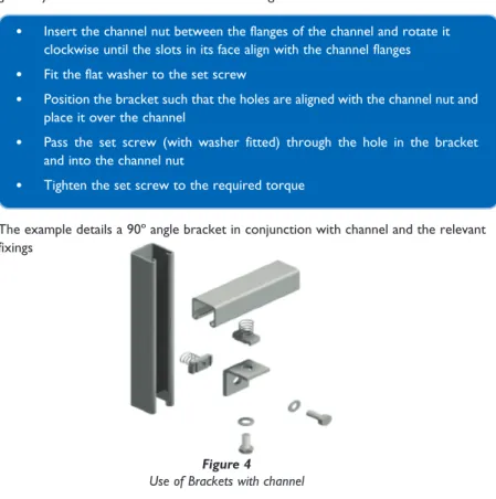
Framework brackets of all types are generally used to aid in the onsite fabrication of a support structure. Brackets (Figure 4) are available to cover most applications and are generally connected to channels in the following fashion:
Long spring Short spring No spring
Figure 3c Typical types of channel nuts
•
Insert the channel nut between the flanges of the channel and rotate it clockwise until the slots in its face align with the channel flanges•
Fit the flat washer to the set screw•
Position the bracket such that the holes are aligned with the channel nut and place it over the channel•
Pass the set screw (with washer fitted) through the hole in the bracket and into the channel nut•
Tighten the set screw to the required torqueFigure 4 Use of Brackets with channel
The example details a 90º angle bracket in conjunction with channel and the relevant fixings
Figures 3 Channel Support Systems
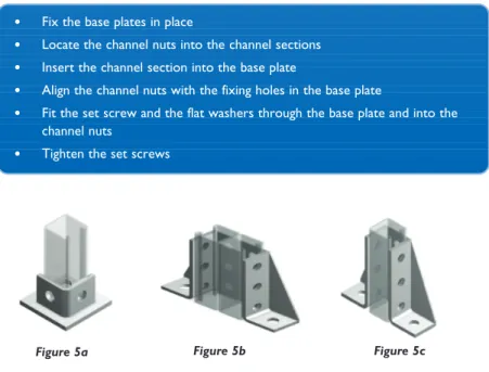
2.3.1.4 Base plates
Base plates (Figures 5) are generally used to fix vertical lengths of channel section to a firm floor and are generally connected to channels in the following fashion:
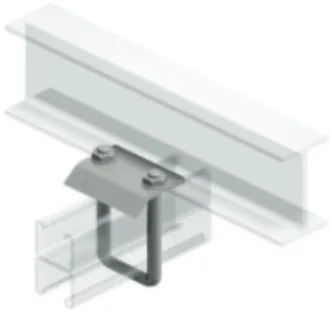
2.3.1.5 Beam clamps – window type
Window type beam clamps (Figure 6a) are generally used to fix lengths of channel section to existing supporting beams and are generally connecting channel to beam for medium loads as shown:
Note: Beam clamps must be used in pairs (one each side)
•
Fix the base plates in place•
Locate the channel nuts into the channel sections•
Insert the channel section into the base plate•
Align the channel nuts with the fixing holes in the base plate•
Fit the set screw and the flat washers through the base plate and into the channel nuts•
Tighten the set screws•
Insert the channel through the hole in the bracket•
Fit the cone pointed set screw through the threaded fixing hole in the bracket•
Position the inner face of the beam clamp against the support structure•
Tighten the set screw to fix the beam clamp in placeFigure 5a Figure 5c
Figures 5 Typical types of Base Plates
2.3.1.6 Beam clamps – ‘U’ bolt type
‘U’ bolt type beam clamps (Figure 6b) are generally used to fix lengths of channel section to existing supporting beams and are generally connecting channel to beam for heavier duty loads as shown:
Note: Beam Clamps must be used in pairs (one each side)
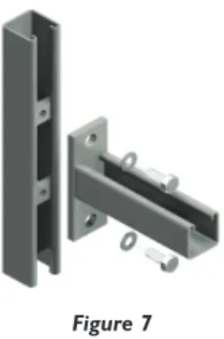
2.3.1.7 Channel type cantilever arms
Channel type cantilever arms (Figure 7) are generally used to provide support to services on a framework installation and are generally connected to channels in the following fashion:
•
Position the U Bolt over the channel and insert it through the holes in the bracket•
Fit the flat washers and nuts to the U Bolt•
Position the U Bolt such that it rests against the edge of the support structure•
Tighten the nuts to fix the beam clamp in placeFigure 6a Figure 6b
•
Insert the channel nuts between the flanges of the channel; and rotate clockwise until the slots in the faces align with the channel flanges•
Fit the flat washers to the set screws•
Position the cantilever arm such that the clearance holes in the back plate are aligned with the threaded holes in the channel nuts•
Pass the set screws (with the washer fitted) through the holes in the backplate into the channel nuts•
Tighten the set screwsFigures 6 Beam clamps
2.3.1.8 Channel type trapeze hangers
Trapeze hangers (Figures 8) are suitable for use with cable ladder and cable tray, supported by threaded rods hung from ceiling brackets, channel support systems or from beam clamps attached to joists or steel beams.
When several levels of cable ladder or cable tray are mounted on the same threaded rods in a multiple level installation, it is important to ensure that the total load on any pair of rods does not exceed the safe working load of the rods or their attachment points.
Figure 7 Channel type cantilever arms
Figures 8 Trapeze hangers using channel
Figure 8b Installation with tray Figure 8a
Assembly is generally carried out in the following order:
Plain channel
•
Secure the top of the threaded rods in accordance with the chosen suspension method.•
Screw a hexagonal nut onto each of the threaded rods and set the nuts at the desired height on the rod.•
Pass a square washer along each rod and screw a channel nut onto the end of each rod.•
Align the channel with the channel nuts and rotate the channel nuts clockwise until the slots in the nuts align with the flanges of the channel.•
Tighten the hexagonal nuts above the channel to secure the assembly.Slotted channel
May be used with single or muliple tiers of trapeze hangers.
•
Secure the top of the threaded rods in accordance with the chosensuspension method.
•
Screw a hexagonal nut onto each of the threaded rods and set the nuts at the desired height on the rod.•
Pass a square washer along each rod and pass the ends of the rods through the slotted channel to form a trapeze.•
Secure the trapeze in place by passing a square washer along the rods and screw a hexagonal nut onto the end of each rod.•
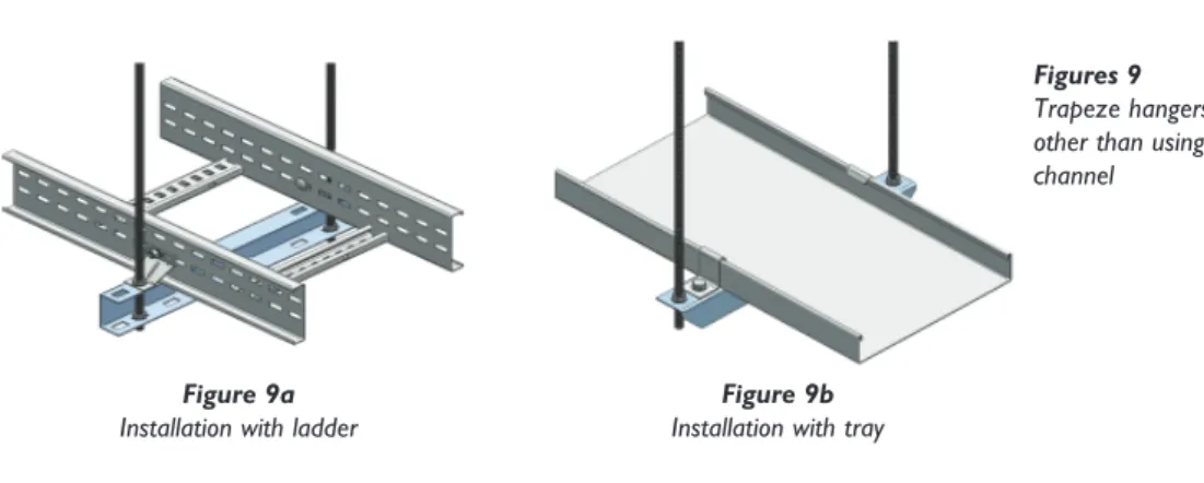
Tighten the hexagonal nuts above and below the channel trapeze hanger to secure the assembly.2.3.2 Supports not using channel to BS 6946 2.3.2.1 Trapeze hangers
Trapeze hangers (Figures 9) are suitable for use with cable ladder and cable tray, supported by threaded rods hung from ceiling brackets, channel support systems or from beam clamps attached to joists or steel beams.
When several levels of cable ladder or cable tray are mounted on the same threaded rods in a multiple level installation, it is important to ensure that the total load on any pair of rods does not exceed the safe working load of the rods or their attachment points.
Consult the manufacturer for specific details.
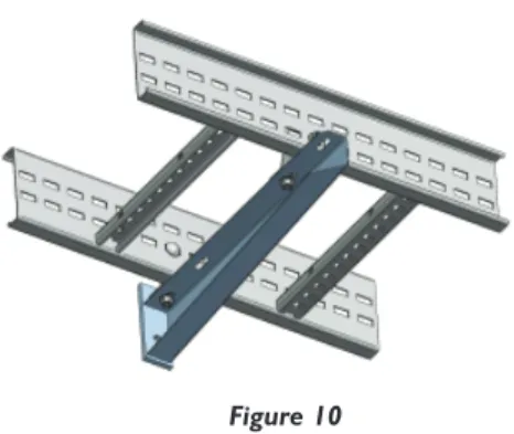
2.3.2.2 Cantilever arms
Cantilever arms enable horizontal runs of cable ladder or cable tray to be mounted to vertical steel, concrete or masonry surfaces or to channel support systems (Figure 10). Consult the manufacturer for specific details.
Figure 9b Installation with tray Figure 9a
Installation with ladder
Figures 9 Trapeze hangers other than using channel
2.3.2.3 Threaded rod suspension brackets
Threaded rod suspension brackets (Figures 11) are useful when space is limited. When several levels of cable ladder or cable tray are mounted on the same threaded rods in a multiple level installation (Figure 11b), it is important to ensure that the total load on any pair of rods does not exceed the safe working load of the rods or their attachment points.
Consult the manufacturer for specific details.
Figure 11b Stacked installation Ladder Figure 10
General installation with ladder
Figures 11 Threaded rod suspension brackets
Figure 11a General installation mesh tray
2.3.2.4 Wall support brackets
Wall support brackets (Figures 12) are an effective way of fixing any width of cable ladder or cable tray, running either vertically or horizontally, to a vertical support. Consult the manufacturer for specific details.
2.3.2.5 Overhead hangers (Specific to cable tray)
Overhead hangers (Figure 13) enable tray to be supported from a single threaded rod giving easy access for laying cables from one side of the tray only.
Consult the manufacturer for specific details
Figures 12 Wall support brackets
Figure 12b
General installation vertical ladder
Figure 12c
General installation horizontal tray (large bracket) Figure 12a
General installation horizontal tray (small bracket)
2.3.2.6 Hold down brackets and clips
Hold down brackets (Figures 14) and clips are used for securing cable ladder and cable tray to horizontal supports. If allowance for thermal expansion is required then the brackets and clips are generally not fixed to the cable ladder or cable tray.
Consult the manufacturer for specific details.
Figures 14 Hold down brackets and clips
Figure 14b
Typical ladder hold down brackets
Figure 14c Typical ladder hold down clips Figure 14a
Typical tray hold down clips
Figure 13 Overhead hanger
Figure 15a Load test Type I 2.3.2.7 Floor and Roof installations
Cable ladders or cable trays should not be laid directly onto the floor or roof of an installation. Cable ladders and cable trays should be mounted far enough off the floor or roof to allow the cables to exit through the bottom of the cable ladder or cable tray. If a channel support system is used for this purpose, mount the channel directly to the floor or roof and attached the cable ladder or cable tray to the channel using the fixings recommended by the manufacturer.
2.4 Straight cable ladder and cable tray lengths 2.4.1 Span size, joint positions and safe loadings
The standard BS EN 61537 states that manufacturers must publish SWL (safe working load) details for their products, and specifies load test methods for determining the SWLs which can be supported by cable ladder and cable tray. There are different types of load test (Figures 15), used dependant on what installation limitations the manufacturer specifies, with regard to span size, possibly with reduced end span size, and positions of joints.
The different test types and the installation conditions for which they are intended are as follows:
IEC load test Type I
Test with a joint in middle of the end span (Figure 15a). Simulates the worst case installation condition. Use for installations with joints anywhere.
IEC load test Type II
Test with a joint in middle of the inner span (Figure 15b), with an optional reduced end span as the manufacturers recommendation.
Simulates an installation condition with span/joint limitations.
Use for installations with no joints in the end spans, with reduced end span as the manufacturer’s recommendation.
Figures 15: Schematics of the SWL Type tests I – IV for cable ladder and cable tray
IEC load test Type III
Test with joints at manufacturers recommended positions (Figures 15c and 15d), with an optional reduced end span as the manufacturer’s recommendation.
Simulates an installation condition with span/joint limitations.
Use for installations with joints at manufacturers recommended positions, with reduced end span as the manufacturer’s recommendation.
Test Type III Example 1 – joints at 1⁄
4span positions
Test Type III Example 2 – joints at support positions:
IEC load test Type IV
A variation on test types I or II, used for products which have a localised weakness in the side member.
The test is identical to test types I & II, but repositioned slightly so that the side member weakness is directly above the middle support.
Use for installations as type I or type II above as appropriate. Figure 15d Load test Type III (example 2)
Span Or reduced end span
Span Span x 0.4
Span Or reduced end span
Span Span x 0.4
Figure 15c Load test Type III (example 1)
Figure 15b Load test Type II Figures 15:
Schematics of the SWL Type tests I – IV for cable ladder and cable tray
It is important when using manufacturers loading data to check what test type has been used to produce the SWL data, and hence what installation limitations may apply, particularly with regard to joint positions & end span size.
For calculation of loadings on a cable ladder or cable tray installation, it is important to include all dead loadings and any imposed loadings such as wind, snow and ice. See section 3.4 for more details.
2.4.2 Straight lengths installation
After the supports are in place, the installation of the cable ladder or cable tray can begin at any convenient location. It is not necessary to begin at one end of the run in all cases. It is ideal if circumstances permit to lay out the system so that joints fall in the desired positions as this will visually aid installation and also maximise the system rigidity. To begin the installation, place a straight length across two supports so that the ends of the length are not directly on the support. If the support span is equal to or greater than the length of the straight lengths then bolt two lengths together for this step.
Place the next straight length across the next support and attach it to the previous length with a pair of coupler plates and relevant fixings with the bolt heads on the inside of the cable ladder or cable tray unless otherwise specified by the manufacturer.
2.4.3 Installation of longer spans
Manufacturer’s published data should be consulted in order to ascertain the maximum span that a product can be used with, and any special provisions required for long spans. Special provisions may be required particularly if used externally where there may be dynamic loadings such as wind & snow; e.g. wider supports, extra supports or bracing, limitations on joint positions.
Span Or reduced end span
Span Span x 0.4
Figure 15e Load test Type IV
Figures 15: Schematics of the SWL Type tests I – IV for cable ladder and cable tray
2.5 Coupler types (refer to manufacturer’s literature)
Couplers are used to join together two separate components, whether that may be lengths, fittings or a combination of both. Couplers are supplied in pairs or individually. 2.5.1 Straight coupler
Straight couplers are used for joining together straight lengths and or fittings. 2.5.2 Fitting to fitting coupler
Depending on the manufacturer fitting to fitting couplers are used for joining together cable ladder fittings (bends, tees, risers etc).
2.5.3 Flexible expansion coupler
Flexible expansion couplers (Figures 16) can be used to:
•
provide a semi-flexible joint where straight cable ladder or cable tray runs span separate structures between which some relative movement is possible.•
make provision for changes in the length of a straight cable ladder or cable tray runs due to thermal expansion or contraction.Figure 16a Concertina expansion coupler
Figure 16b Sliding expansion coupler Figures 16
Expansion couplers
2.5.3.1 Distance between expansion joints
The distance between expansion joints (Figure 17) should be calculated by the following formula.
D = E/(KT) Where
D = distance between expansion joints (m)
E = allowable movement for each expansion joint (m)
T = temperature range [Maximum temperature – minimum temperature] (ºC) K = coefficient of linear expansion of the material (ºC-1)
Typical values for K • Mild steel 13 x10-6
• Stainless steel grade 1.4404 (316) 16 x10-6 • GRP Variable (consult manufacturer) • PVC 55 x10-6
2.5.3.2 Example calculation using a typical sliding type expansion coupler Mild steel cable ladder, with K = 13 x 10-6°C-1
Allowable movement at each expansion joint E = 28 mm = 0.028 m Temperature range of installation T = -15 ºC to +35 ºC = 50 ºC Maximum distance ‘D’ between expansion joints
D=E/(KT) =0.028/(13 x 10-6x 50) = 43 m
For ease of installation an expansion coupler should be fitted every 14th length of 3m ladder giving 42m between expansion couplers.
Figure 17
Method for determining the installation gap for sliding type expansion couplers. Using the graph (Figure 18) below:
• Mark the maximum seasonal temperature on line A • Mark the minimum seasonal temperature on line B
• Draw a diagonal line C between the two marked points on line A and B
• Draw line D horizontally at the temperature the cable ladder or cable tray is to be installed at.
• A vertical line E should then be constructed from the intersection of the diagonal line C and the horizontal line D
• The installed gap setting can read off the base of the graph (F).
Note the gap setting will vary depending on the manufacturers design. The example above is for a coupler with a total 28 mm expansion range.
2.5.3.3 Example calculation using a typical concertina type expansion coupler Mild steel cable ladder, with K = 13 x 10-6°C-1
Allowable movement at each expansion joint E = ±10 mm = ± 0.01 m Temperature range of installation T = -20 °C to +40 °C = 60 °C
Figure 18
Figure 20 Vertical hinged couplers
Maximum distance ‘D’ between expansion joints D = E/(KT) = 0.01/(13 x 10-6x 60) = 12.8 m
For ease of installation an expansion coupler should be fitted every 4th length of 3m ladder giving 12 m between expansion couplers.
As the temperature at the time of installation is unknown the expansion movement of the coupler (in this example) would range from + 10 mm to – 10 mm depending on the temperature at the time of installation. The value of ‘E’ therefore used for the calculation is half of the total range of movement of the coupler.
NOTE at expansion joint positions supports should be no more than 600 mm either side of the joint, unless special strong expansion couplers are available that allow supports to be positioned greater than 600 mm from the joint.
Figure 19 Bendable couplers
2.5.5 Vertical hinged coupler
Vertical hinged couplers (Figure 20) can be used for:
• Fabricating fittings on site from cut lengths of cable ladder.
• Solving minor vertical misalignment problems. • Coupling articulated risers to adjacent cable
ladders.
• Forming risers at non-standard angles.
2.5.4 Horizontal Adjustable/Bendable coupler Bendable couplers (Figure 19) can be used for: • Fabricating fittings on site from cut lengths of
cable ladder.
• Correcting minor misalignment problems. • Coupling lengths of cable ladder to form
Figure 21 Horizontal hinged couplers 2.5.6 Horizontal hinged coupler
Horizontal hinged couplers (Figure 21) can be used for:
• Fabricating fittings on site from cut lengths of cable ladder.
• Solving minor horizontal misalignment problems.
• Forming horizontal bends at non-standard angles.
2.7 Fittings
Fittings are best described as factory fabricated items which facilitate a change of direction and / or width and provide intersections between straight cable ladder or cable tray runs. A standard range of fittings would include such items as a flat bend, inside or outside riser, equal or unequal tee, 4-way crossover & reducer. Other fittings may also be available and consultation with the manufacturer may be necessary. In cable management installations fittings must always be provided with local support.
2.7.1 Radius of cable ladder and cable tray fittings
The radius for cable ladder and cable tray fittings is usually determined by the bending radius and stiffness of the cables installed on the cable ladder or cable tray. Typically the cable manufacturer will recommend a minimum bend allowance for each type of cable. The radius of the cable ladder or cable tray fitting should be equal to or larger than the minimum bending radius of the largest cable installed.
2.7.3 Fittings without integral coupler
Fittings without integral couplers are normally joined together and/or to straight lengths using couplers as used with straight lengths.
2.6 Fixings
It is important that the manufacturers or responsible vendors
recommended fixings should be used and tightened to the specified torque in order to ensure a safe and secure installation of the system including: • Adequate mechanical strength,
• Electrical continuity (if required),
• Resistance to corrosion (see section 3.1 Environment), and • Prevention of damage to cables.
The use of incorrect or unspecified fixings may result in the above requirements being severely compromised
1. Straight length tray or ladder 2. Fitting of tray or ladder
3. Support position under adjacent straight length
Figure 22b Riser support
2.7.4 Support locations for cable ladder and cable tray fittings
Where fittings are used, supports are usually required under the adjacent straight lengths close to the fitting joints (Figures 22).
Additional supports are sometimes required directly underneath large fittings (see key item 4 in the relevant figures below).
Consult manufacturers’ published data for details of the maximum distance between supports & fitting joints, and for which size fittings require additional supports.
1. Straight length tray or ladder 2. Fitting of tray or ladder
3. Support position under adjacent straight length 4. Additional support position under large fittings
Figure 22a Flat Elbow support
Figures 22: Support locations for cable ladder fittings and cable tray fittings
1. Straight length tray or ladder 2. Fitting of tray or ladder 3. Support position under adjacent
straight length
4. Additional support position under large fittings
Figure 22c Tee support
1. Straight length tray or ladder 2. Fitting of tray or ladder 3. Support position under adjacent straight length
Figure 22e Reducer support 1. Straight length tray or ladder
2. Fitting of tray or ladder
3. Support position under adjacent straight length 4. Additional support position under large fittings
Figure 22d Crossover support Figures 22
Support locations for cable ladder fittings and cable tray fittings
2.8 Accessories
An accessory is a component used for supplementary function such as cable retention, covers and dividers etc.
2.8.1 Dividers
Dividers are used to physically separate different types or groups of cable within one cable ladder or cable tray run. The divider is usually manufactured from the same material as the cable ladder or cable tray onto which it is installed.
Dividers should be installed prior to the cable being laid and then fastened using the fixings recommended by the manufacturer.
2.8.2 Covers
Covers provide mechanical and environmental protection for cables being carried by cable ladder or cable tray, can be closed or ventilated and should be fitted in accordance with the manufacturer’s instructions.
2.9 Site modification 2.9.1 General
No installation will be perfect and at sometime it may become necessary to cut the cable ladder or cable tray during installation. Care must be taken to ensure that all modifications made on site to cable ladder or cable tray are performed by competent personnel only.
2.9.2 Repair of damaged surfaces
Cable ladders or cable trays that have been hot dip galvanized after manufacture will need to be repaired after cutting, drilling and de-burring. Cutting operations leave bare metal edges that will begin to corrode immediately. Cable ladder and cable tray made from mill galvanized steels do not need to be repaired because they are not designed to be used in heavily corrosive atmospheres and have bare metal edges inherent in their design.
Repairing a galvanized finish must be done in accordance with BS EN ISO 1461 usually using a zinc rich paint. Other protective coatings that are cut or damaged must be repaired with compatible coatings.
2.10 Earth protection and EMC 2.10.1 Protection of cables
Cable ladder and cable tray systems are designed to provide continuous support to any cables installed upon them. Due to the fact that cable ladders and cable trays are never really fully enclosed they do not offer complete mechanical and environmental protection. For this reason unsheathed, single insulated power cables should not be installed on cable ladder and cable tray. Cable installed on cable ladder and cable tray should have some form of mechanical protection in the form of PVC sheathing, steel wire armouring or a copper covering (MICC).
Where moisture may be present, copper covered cables must also be PVC Sheathed to avoid electrochemical corrosion between the copper and a metallic cable support system.
2.10.2 Electrical continuity
Cable ladder and cable tray systems that are electrically conductive should have adequate electrical continuity to ensure equipotential bonding and connections to earth. Installations shall comply with the requirements of BS 7671 (The Wiring Regulations). Manufacturers are required by BS EN 61537 to declare whether or not their systems are classified as having electrical continuity characteristics.
2.10.3 EMC
Cable ladder and cable tray systems on their own are passive in respect of electromagnetic influences. The installation of current carrying cable however, may cause electromagnetic emissions that may influence information technology cables. As a guide for the installation of IT cables it is recommended that BS EN 50174-2 is consulted.
2.11 Preparation
Prior to installing cable in the tray or ladder, examine the cable paths to ensure all areas are free of debris that may interfere with the cable’s installation. Surface areas of tray or ladder components likely to come into contact with cables shall not cause damage to the cables when installed according to the manufacture’s instruction or this guide
Cable tray or cable ladder should never be used as a walkway. 2.12 Wiring Regulations
The installation of cables shall meet the requirements of BS 7671 (The Wiring Regulations) or other national requirements as applicable.
2.13 Power Cables
2.13.1 Pulling Considerations
Where cables are large or cable runs are long, their installation may require pulling tools (Figures 23 and 24); in such cases the following is recommended.
•
On horizontal straight runs, the cables generally ride on rollers mounted in or on the cable tray or cable ladder (Figure 23a). These rollers should be properly spaced dependent on the size and weight of the cable to prevent the cable from sagging and dragging in the cable tray or cable ladder during the pull. Contact the cable manufacturer for information regarding proper roller spacing.SECTION 2B
Installation of Cable
Figure 23a Straight Roller
Figures 23 Cable guides for pulling cables
Figure 23c Pulley Guide Figure 23b
90º Roller Figures 23 Cable
guides for pulling cables
•
On horizontal bends and vertical pulls, the cables are generally run through rollers or pulleys to maintain a minimum bending radius (Figures 23b and 23c). Rollers and pulleys must be of sufficient diameter to prevent pinching the cable between the roller/ pulley flanges. Each cable will have a minimum bending radius that must be maintained to prevent damage to the cable. Information on cable bending radii can be obtained from Table 1. Multiple pulling tools may be required at one bend to maintain this radius. Care should be taken with the entry and exit angle of the cable at the pulling tool, as this angle can exceed the bending radius.•
Due to the length of some cable pulls and the cable weight, a great deal of force can be applied to the pulleys on horizontal and vertical bends. These pulleys should be anchored to the structural steel and not to the cable tray or cable ladder due to the force that can be applied during pulling. Do not pull down on the horizontal rollers, as they are not designed for this purpose, and damage could result to the cable, cable tray or cable ladder.Factor to be applied to overall diameter of cable to determine minimum internal radius of bend Overall diameter * Insulation Finish Thermosetting or thermoplastic (circular, or circular stranded copper or aluminium conductors) Thermosetting or thermoplastic (solid aluminium or shaped copper conductors) Mineral Flexible cables Non-armoured Armoured Armoured or non- armoured
Copper sheath with or without covering Sheathed Not exceeding 10 mm Exceeding 10 mm but not exceeding 25 mm Exceeding 25 mm Any Any Any Any 3(2)† 4(3)† 6 6 8 6‡ No specific provision but no tighter than equivalent sized non-armoured cable**
* For flat cable the diameter refers to the major axis.
† The figure in brackets relates to single-core circular conductors of stranded construction installed in conduit, ducting or trunking.
‡ For mineral insulated cables, the bending radius shall normally be limited a minimum of 6 times the diameter of the bare copper sheath, as this will allow further straightening and reworking if necessary. However, cables may be bent to a radius not less than 3 times the cable diameter over the copper sheath, provided that the bend is not reworked.
** Flexible cables can be damaged by too tight or repeated bending.
Note Table 1 (equivalent to Table G.2) extracted from ‘Guidance Note 1 Selection and Erection’ to BS 7671
Table 1 Minimum internal bending radii of bends in cables for fixed wiring
2.13.2 Pulling the cable
Larger cables will usually require a pulling sock (basket grip) and/or pulling eye to be attached to the leading end of the cables metallic conductor(s). If the cable does not have a pulling eye attached by the manufacturer, the cable manufacturer should be contacted for information on field installation of a pulling sock and/or pulling eye (Figures 24a and 24b). Where pulling attachments are used on the conductors, they should be covered with protective tape or similar to prevent scoring of the cable trays, cable ladders and installation pulleys.
Cables generally have pulling tension restrictions, so a dynamometer may be installed at the pulling end in order to ensure that the cable’s maximum pulling tension is not exceeded. The cable should be pulled at a constant speed. The maximum pulling tension and cable pulling speed cable can be obtained from the cable manufacturer. Cables should be placed and not dropped in to the cable tray or cable ladder.
2.13.3 Fastening
•
Cables should be fastened to the cable ladder and/or cable tray using cable cleats or cable ties to prevent movement of the cables under normal use and during fault conditions (Figures 25a and 25b). Generally the spacing between cable fastenings should not exceed the dimensions stated in Table 2. For some applications where the fault current level requires it, spacing between cable fastenings may be less than those stated in Table 2. Where this applies details should be obtained from the electrical installation designer and/or the supplier of the fastenings. Cable cleats and cable ties should be correctly sized and only tightened enough to secure the cable without indenting the insulation sheath.•
On vertical runs the fastenings must be able to withstand the forces exerted by the weight of the cable. The cable weight should be supported in such a manner as to prevent damage to the cable ladder, cable tray or cable.Figure 24b Cable pulling eye Figure 24a
Cable pulling sock Figures 24
Cable pulling tools
•
Where possible it is best practice to position cable cleats on alternate rungs of the cable ladder in order to evenly spread the load along the length of the cable ladder as illustrated in Figure 25a.Table 2 Spacings of supports for cables in accessible positions Figure 25b
Cable attached to tray using cable ties Figure 25a
Cable attached to ladder using cable cleats
1 Horizontal† 2
d≤9 250
9<d≤15 300 400 350 450 900 1200
400 250
(for all sizes) (for all sizes)400 - - 600 800
Vertical† 3 Vertical† 5 Vertical† 7 Vertical† 9 Horizontal† 4 Horizontal† 6 Horizontal† 8 15<d≤20 350 450 400 550 1500 2000 20<d≤40 400 550 450 600 - -Non-armoured thermosetting or
thermoplastic (PVC) sheathed cables Armoured cables
Generally In caravans
Mineral insulated copper sheathed or aluminium sheathed cables Overall diameter of cable, d* (mm)
Maximum spacings of clips (mm)
Note: For the spacing of supports for cables having an overall diameter exceeding 40 mm, the manufacturer’s recommendation should be observed.
* For flat cables taken as the dimension of the major axis.
† The spacings stated for horizontal runs may be applied also to the runs at an angle of more than 30º from the vertical. For runs at an angle of 30º or less from the vertical, the vertical spacings are applicable.
Note Table 2 (equivalent to Table 4A) extracted from the Onsite Guide to BS 7671
Figures 25 Cable fastening devices
2.14 Data Cables 2.14.1 Installation
There are some general rules that apply to the installation of all data cable bundles, regardless of containment type, and they are:
Cable ties must not be too tight. Any cable within a tied bundle must be able to be moved through that tie with slight resistance. Data and optical cables cannot stand the same heavy-duty ‘lashing’ as power cables. The tie must not be too thin as it may cut into the sheath of the cable.
The minimum bend radius shall not be less than that specified by the cable manufacturer. Manufacturers generally specify six to eight times the cable diameter as the cable bend radius.
There is no exact or correct figure for the amount of cables allowed in any one bundle, typically a figure of between 24 and 48 cables is used.
2.14.2 Segregation
Where power and data cables are installed within the same containment system or within close proximity to each other, suitable segregation shall be used. Guidance on segregation can be found from BS 6701 and BS EN 50174.
2.15 Expansion
Where expansion joints are present in the cable tray or cable ladder installation, provision must be made for the cable to expand and contract correspondingly. This is usually achieved with a loop in the cable at the expansion joint position.
2.16 Electro Mechanical Effects Electrical Short Circuits
When an electrical short circuit occurs under fault conditions the current that flows can in some instances reach tens of thousands of amps which can last from a few milliseconds to several seconds depending on the electrical installation requirements. Such short circuit currents produce high magnetic fields which can interact to produce large mechanical forces. These forces can cause significant displacement of the cables and therefore some form of restraint must be provided to prevent damage to the cables. For large diameter cables the most common form of restraint is by the use of cable cleats which hold the cables to the cable ladder or cable tray. Some of the force may therefore be transferred to the cable ladder or cable tray via the cable cleat, and could be sufficient to cause damage to the ladder or tray.
The calculation of the forces is complex and the effect on a cable ladder or cable tray can only be fully determined by testing. See photographs below showing the effects of testing.
Where such large electrical fault currents could possibly occur then the cable ladder/cable tray/cable cleat manufacturers should be consulted.
For reference the calculation of the forces between two conductors can be carried out using the formula given in BS EN 61914:2009:
Where:
F = force in N m-1
ip= peak prospective short circuit current in kA S = spacing between the conductors in m
However the ‘F Value’ is the force within the ‘loop’ of the cleat and does not indicate how much of this force transfers into the structure, or containment, which the cleat is fastened to. Hence the only certain way to assess that the cable support system is strong enough to resist the mechanical force is by testing.
Displacement of cables when subjected to high short circuit currents