M95
AT Commands Manual
GSM/GPRS Module Series
Rev. M95_AT_Commands_Manual_V3.1
Date: 2014-09-16
www.quectel.comOur aim is to provide customers with timely and comprehensive service. For any
assistance, please contact our company headquarters:
Quectel Wireless Solutions Co., Ltd.
Office 501, Building 13, No.99, Tianzhou Road, Shanghai, China, 200233 Tel: +86 21 5108 6236
Mail: [email protected]
Or our local office, for more information, please visit:
http://www.quectel.com/support/salesupport.aspxFor technical support, to report documentation errors, please visit:
http://www.quectel.com/support/techsupport.aspxGENERAL NOTES
QUECTEL OFFERS THIS INFORMATION AS A SERVICE TO ITS CUSTOMERS. THE INFORMATION PROVIDED IS BASED UPON CUSTOMERS’ REQUIREMENTS. QUECTEL MAKES EVERY EFFORT TO ENSURE THE QUALITY OF THE INFORMATION IT MAKES AVAILABLE. QUECTEL DOES NOT MAKE ANY WARRANTY AS TO THE INFORMATION CONTAINED HEREIN, AND DOES NOT ACCEPT ANY LIABILITY FOR ANY INJURY, LOSS OR DAMAGE OF ANY KIND INCURRED BY USE OF OR RELIANCE UPON THE INFORMATION. ALL INFORMATION SUPPLIED HEREIN IS SUBJECT TO CHANGE WITHOUT PRIOR NOTICE.
COPYRIGHT
THIS INFORMATION CONTAINED HERE IS PROPRIETARY TECHNICAL INFORMATION OF QUECTEL CO., LTD. TRANSMITTABLE, REPRODUCTION, DISSEMINATION AND EDITING OF THIS DOCUMENT AS WELL AS UTILIZATION OF THIS CONTENTS ARE FORBIDDEN WITHOUT PERMISSION. OFFENDERS WILL BE HELD LIABLE FOR PAYMENT OF DAMAGES. ALL RIGHTS ARE RESERVED IN THE EVENT OF A PATENT GRANT OR REGISTRATION OF A UTILITY MODEL OR DESIGN.
Copyright © Quectel Wireless Solutions Co., Ltd. 2014. All rights reserved.
Quectel
About the Document
History
Revision Date Author Description
1.0 2011-12-30 Jean HU Initial
1.1 2012-03-20 Vivian WANG
1. Modified flow control
2. Added new parameters for AT+QNITZ/ AT+QBAND
3. Added AT commands:
AT+QLTS/AT+QLDTMF/AT+QLTONE/AT+QSFR/ AT+QSPCH/AT+QMUXC
4. Deleted fax related commands 5. Deleted AT commands: AT+QECHO/AT+QSIMDET/AT+QECHOEX/AT+Q EAUART/AT+QSEDCB/AT+QSIMSTAT/AT+QTE MP/AT+AUDLOOP/AT+QLOCKF/AT+EGPAU/AT+ QTUNBUF/AT+CRSM/AT+QDISP/AT+QCGTIND 1.2 2013-07-16 Jelly WANG 1. Added AT commands: AT+QSPN/AT+QTRPIN/AT+QISTATE/AT+QISSTA T/AT+QLTONE/AT+QTONEP/AT+QTDMOD/AT+ QTONEDET/AT+QWDTMF/AT+QLEDMODE/AT+ QALARM/AT+CRSM/AT+CSIM/AT+QCSPWD/AT +QENG/AT+QSCANF/AT+QLOCKF/AT+QTEMP/ A/
2. Added new parameters for AT+VTD
3. Added the value range of parameters for AT+CTZU/AT+QIPROMPT/AT+QSCLK/AT+QSM SCODE/AT+QRIMODE/AT+QMIC
4. Modified the description of the AT command: AT+CSCS/AT+QPOWD/AT+CFUN/AT&D/AT+CP MS/AT+QISSTAT/AT+QISEND
1.3 2013-11-25 Karen REN Added maximum response time to all AT commands.
Quectel
3.0 2014-08-05 Jessica GENG Added AT commands: AT+QGSN/AT+CCID
3.1 2014-09-16 Jessica GENG
1. Modified AT command: AT+QSCLK 2. Deleted AT commands: AT+CACM/AT+CAMM/AT+CAOC/AT+CCWE/AT+ CPUC/AT+CSIM/AT+CCID 3. Added AT commands: AT+QDSIM/AT+QCOLP/AT+QCLIP
Quectel
Confidential
Contents
About the Document ... 2
Contents ... 4
Table Index ... 10
1 Introduction ... 11
1.1. Scope of the Document ... 11
1.2. AT Command Syntax ... 11
1.2.1. Combining AT Commands on the Same Command Line ... 12
1.2.2. Entering Successive AT Commands on Separate Lines ... 12
1.3. Supported Character Sets ... 12
1.4. Flow Control ... 13
1.4.1. Software Flow Control (XON/XOFF Flow Control) ... 13
1.4.2. Hardware Flow Control (RTS/CTS Flow Control) ... 14
1.5. Unsolicited Result Code ... 14
2 General Commands ... 15
2.1. ATI Display Product Identification Information ... 15
2.2. AT+GMI Request Manufacturer Identification ... 15
2.3. AT+GMM Request TA Model Identification ... 16
2.4. AT+GMR Request TA Revision Identification of Software Release ... 16
2.5. AT+GOI Request Global Object Identification ... 17
2.6. AT+CGMI Request Manufacturer Identification ... 18
2.7. AT+CGMM Request Model Identification ... 18
2.8. AT+CGMR Request TA Revision Identification of Software Release ... 19
2.9. AT+GSN Request International Mobile Equipment Identity (IMEI) ... 19
2.10. AT+CGSN Request Product Serial Number Identification (Identical with +GSN) ... 20
2.11. AT+QGSN Request Product Serial Number Identification (IMEI) ... 20
2.12. AT&F Set all Current Parameters to Manufacturer Defaults ... 21
2.13. AT&V Display Current Configuration ... 21
2.14. AT&W Store Current Parameter to User Defined Profile ... 23
2.15. ATQ Set Result Code Presentation Mode ... 24
2.16. ATV TA Response Format ... 24
2.17. ATX Set CONNECT Result Code Format and Monitor Call Progress ... 26
2.18. ATZ Set all Current Parameters to User Defined Profile ... 27
2.19. AT+CFUN Set Phone Functionality ... 27
2.20. AT+QPOWD Power off ... 29
2.21. AT+CMEE Report Mobile Equipment Error ... 29
2.22. AT+CSCS Select TE Character Set ... 30
2.23. AT+GCAP Request Complete TA Capabilities List ... 32
3 Serial Interface Control Commands ... 33
3.1. AT&C Set DCD Function Mode ... 33
3.2. AT&D Set DTR Function Mode ... 33
Quectel
3.3. AT+ICF Set TE-TA Control Character Framing ... 34
3.4. AT+IFC Set TE-TA Local Data Flow Control... 35
3.5. AT+ILRR Set TE-TA Local Data Rate Reporting Mode ... 36
3.6. AT+IPR Set TE-TA Fixed Local Rate ... 37
3.6.1. Adaptive Baud ... 39
3.7. AT+CMUX Multiplexer Control ... 40
4 Status Control Commands ... 42
4.1. AT+CEER Extended Error Report ... 42
4.2. AT+CPAS Mobile Equipment Activity Status ... 43
4.3. AT+QINDRI Indicate RI When Using URC ... 44
4.4. AT+QMOSTAT Show State of Mobile Originated Call ... 45
4.5. AT+QIURC Enable or Disable Initial URC Presentation ... 46
4.6. AT+QEXTUNSOL Enable/Disable Proprietary Unsolicited Indications ... 46
4.7. AT+QINISTAT Query State of Initialization ... 48
4.8. AT+QNSTATUS Query GSM Network Status ... 49
4.9. AT+QNITZ Network Time Synchronization... 49
4.10. AT+QLTS Obtain Latest Network Time Synchronized ... 50
4.11. AT+CTZU Network Time Synchronization and Update the RTC Time ... 51
4.12. AT+CTZR Network Time Synchronization Report ... 52
5 SIM Related Commands ... 53
5.1. AT+CIMI Request International Mobile Subscriber Identity (IMSI) ... 53
5.2. AT+CLCK Facility Lock ... 54
5.3. AT+CPIN Enter PIN ... 56
5.4. AT+CPWD Change Password ... 57
5.5. AT+CRSM Restricted SIM Access ... 59
5.6. AT+QCSPWD Change PS Super Password ... 60
5.7. AT+QCCID Show ICCID ... 60
5.8. AT+QGID Get SIM Card Group Identifier ... 61
5.9. AT+QSIMVOL Select SIM Card Operating Voltage... 62
5.10. AT+QSPN Get Service Provider Name from SIM ... 62
5.11. AT+QTRPIN Times Remain to Input SIM PIN/PUK ... 63
5.12. AT+QDSIM Dual SIM Switch ... 64
6 Network Service Commands ... 66
6.1. AT+COPS Operator Selection ... 66
6.2. AT+CREG Network Registration ... 68
6.3. AT+CSQ Signal Quality Report ... 69
6.4. AT+CPOL Preferred Operator List ... 70
6.5. AT+COPN Read Operator Names... 71
6.6. AT+QBAND Get and Set Mobile Operation Band ... 72
6.7. AT+QENG Switch on or off Engineering Mode ... 73
6.8. AT+QSCANF Scan Power of GSM Frequency ... 76
6.9. AT+QLOCKF Lock GSM Frequency ... 77
Quectel
7 Call Related Commands ... 78
7.1. ATA Answer an Incoming Call ... 78
7.2. ATD Mobile Originated Call to Dial a Number ... 79
7.3. ATH Disconnect Existing Connection ... 80
7.4. +++ Switch from Data Mode to Command Mode ... 81
7.5. ATO Switch from Command Mode to Data Mode ... 82
7.6. ATP Select Pulse Dialing ... 82
7.7. ATS0 Set Number of Rings before Automatically Answering Call ... 83
7.8. ATS6 Set Pause before Blind Dialing ... 83
7.9. ATS7 Set Number of Seconds to Wait for Connection Completion ... 84
7.10. ATS8 Set the Number of Seconds to Wait for Comma Dial Modifier ... 85
7.11. ATS10 Set Disconnect Delay after Indicating the Absence of Data Carrier ... 85
7.12. ATT Select Tone Dialing ... 86
7.13. AT+CSTA Select Type of Address ... 86
7.14. AT+CLCC List Current Calls of ME ... 87
7.15. AT+CR Service Reporting Control ... 88
7.16. AT+CRC Set Cellular Result Codes for Incoming Call Indication ... 89
7.17. AT+CRLP Select Radio Link Protocol Parameter ... 91
7.18. AT+CSNS Single Numbering Scheme ... 92
7.19. AT+CMOD Configure Alternating Mode Calls ... 92
7.20. AT+QSFR Preference Speech Coding ... 93
7.21. AT+QSPCH Speech Channel Type Report ... 94
7.22. AT+QDISH Disable ATH ... 95
8 SMS Commands ... 96
8.1. AT+CSMS Select Message Service ... 96
8.2. AT+CMGF Select SMS Message Format ... 97
8.3. AT+CSCA SMS Service Center Address ... 97
8.4. AT+CPMS Preferred SMS Message Storage ... 99
8.5. AT+CMGD Delete SMS Message ... 100
8.6. AT+CMGL List SMS Messages from Preferred Store ... 101
8.7. AT+CMGR Read SMS Message ... 104
8.8. AT+CMGS Send SMS Message ... 107
8.9. AT+CMGW Write SMS Message to Memory ... 109
8.10. AT+CMSS Send SMS Message from Storage ... 110
8.11. AT+CMGC Send SMS Command ...111
8.12. AT+CNMI New SMS Message Indications ... 112
8.13. AT+CRES Restore SMS Settings ... 115
8.14. AT+CSAS Save SMS Settings ... 116
8.15. AT+CSCB Select Cell Broadcast SMS Messages ... 116
8.16. AT+CSDH Show SMS Text Mode Parameters ... 117
8.17. AT+CSMP Set SMS Text Mode Parameters ... 118
8.18. AT+QCLASS0 Store Class 0 SMS to SIM when Receiving Class 0 SMS ... 119
8.19. AT+QMGDA Delete all SMS ... 120
8.20. AT+QSMSCODE Configure SMS Code Mode ... 121
Quectel
9 Phonebook Commands ... 123
9.1. AT+CPBS Select Phonebook Memory Storage ... 123
9.2. AT+CPBW Write Phonebook Entry ... 124
9.3. AT+CPBR Read Current Phonebook Entries ... 125
9.4. AT+CPBF Find Phonebook Entries ... 126
9.5. AT+CNUM Subscriber Number ... 127
10 GPRS Commands ... 129
10.1. AT+CGATT Attach to/Detach from GPRS Service ... 129
10.2. AT+CGDCONT Define PDP Context ... 130
10.3. AT+CGQREQ Quality of Service Profile (Requested)... 131
10.4. AT+CGQMIN Quality of Service Profile (Minimum Acceptable) ... 132
10.5. AT+CGACT PDP Context Activate or Deactivate ... 133
10.6. AT+CGDATA Enter Data State ... 134
10.7. AT+CGPADDR Show PDP Address ... 135
10.8. AT+CGCLASS GPRS Mobile Station Class ... 136
10.9. AT+CGEREP Control Unsolicited GPRS Event Reporting ... 137
10.10. AT+CGREG Network Registration Status ... 138
10.11. AT+CGSMS Select Service for MO SMS Messages ... 139
10.12. AT+QGPCLASS Change GPRS Multi-slot Class ... 140
11 TCPIP Commands ... 141
11.1. AT+QIOPEN Start up TCP or UDP Connection ... 141
11.2. AT+QISEND Send Data through TCP or UDP Connection ... 142
11.3. AT+QICLOSE Close TCP or UDP Connection ... 143
11.4. AT+QIDEACT Deactivate GPRS/CSD PDP Context ... 145
11.5. AT+QILPORT Set Local Port ... 145
11.6. AT+QIREGAPP Start TCPIP Task and Set APN, User Name and Password ... 146
11.7. AT+QIACT Activate GPRS/CSD Context ... 147
11.8. AT+QILOCIP Get Local IP Address ... 147
11.9. AT+QISTAT Query Current Connection Status ... 148
11.10. AT+QISTATE Query Connection Status of the Current Access ... 150
11.11. AT+QISSTAT Query the Current Server Status ... 151
11.12. AT+QIDNSCFG Configure Domain Name Server ... 152
11.13. AT+QIDNSGIP Query the IP Address of Given Domain Name ... 153
11.14. AT+QIDNSIP Connect with IP Address or Domain Name Server ... 154
11.15. AT+QIHEAD Add an IP Header when Receiving Data ... 154
11.16. AT+QIAUTOS Set Auto Sending Timer ... 155
11.17. AT+QIPROMPT Set Prompt of ‘>’ when Sending Data ... 156
11.18. AT+QISERVER Configured as Server... 156
11.19. AT+QICSGP Select CSD or GPRS as the Bearer ... 157
11.20. AT+QISRVC Choose Connection ... 159
11.21. AT+QISHOWRA Set Whether or Not to Display the Address of Sender ... 159
11.22. AT+QISCON Save TCPIP Application Context ... 160
11.23. AT+QIMODE Select TCPIP Transfer Mode ... 162
Quectel
11.24. AT+QITCFG Configure Transparent Transfer Mode ... 162
11.25. AT+QISHOWPT Control Whether or Not to Show the Protocol Type ... 163
11.26. AT+QIMUX Control Whether or Not to Enable Multiple TCPIP Session ... 164
11.27. AT+QISHOWLA Control Whether or Not to Display Local IP Address ... 165
11.28. AT+QIFGCNT Select a Context as Foreground Context ... 166
11.29. AT+QISACK Query the Data Information for Sending ... 166
11.30. AT+QINDI Set the Method to Handle Received TCP/IP Data ... 167
11.31. AT+QIRD Retrieve the Received TCP/IP Data ... 168
11.32. AT+QISDE Control Whether or Not to Echo the Data for QISEND ... 169
11.33. AT+QPING Ping a Remote Server ... 170
11.34. AT+QNTP Synchronize the Local Time Via NTP ... 171
12 Supplementary Service Commands ... 173
12.1. AT+CCFC Call Forwarding Number and Conditions Control ... 173
12.2. AT+CCUG Closed User Group Control ... 175
12.3. AT+CCWA Call Waiting Control ... 176
12.4. AT+CHLD Call Hold and Multiparty ... 177
12.5. AT+CLIP Calling Line Identification Presentation ... 179
12.6. AT+QCLIP Display the +CLIP Number Name ... 181
12.7. AT+CLIR Calling Line Identification Restriction ... 182
12.8. AT+COLP Connected Line Identification Presentation ... 183
12.9. AT+QCOLP Display the +COLP Number Name ... 184
12.10. AT+CUSD Unstructured Supplementary Service Data ... 185
12.11. AT+CSSN Supplementary Services Notification ... 186
13 Audio Commands ... 188
13.1. ATL Set Monitor Speaker Loudness ... 188
13.2. ATM Set Monitor Speaker Mode ... 188
13.3. AT+VTD Tone Duration ... 189
13.4. AT+VTS DTMF and Tone Generation... 190
13.5. AT+CALM Alert Sound Mode ... 191
13.6. AT+CRSL Ringer Sound Level ... 191
13.7. AT+CLVL Loud Speaker Volume Level ... 192
13.8. AT+CMUT Mute Control ... 193
13.9. AT+QSIDET Change the Side Tone Gain Level ... 193
13.10. AT+QMIC Change the Microphone Gain Level ... 194
13.11. AT+QLDTMF Generate Local DTMF Tones ... 195
13.12. AT+QAUDCH Swap the Audio Channels ... 196
13.13. AT+QLTONE Generate Local Specific Tone ... 196
13.14. AT+QTONEP Set DTMF Output Path ... 197
13.15. AT+QTDMOD Set Tone Detection Mode ... 198
13.16. AT+QTONEDET Detect DTMF ... 199
13.17. AT+QWDTMF Play DTMF Tone During the Call ... 201
14 Hardware Related Commands ... 204
14.1. AT+CCLK Clock ... 204
Quectel
14.2. AT+QALARM Set Alarm... 205
14.3. AT+CBC Battery Charge... 206
14.4. AT+QSCLK Configure Slow Clock... 206
14.5. AT+QTEMP Query the Current Voltage and Temperature ... 207
14.6. AT+QLEDMODE Configure the Network LED Patterns ... 208
15 Others Commands ... 209
15.1. A/ Re-issues the Last Command Given ... 209
15.2. ATE Set Command Echo Mode ... 209
15.3. ATS3 Set Command Line Termination Character ... 210
15.4. ATS4 Set Response Formatting Character ... 210
15.5. ATS5 Set Command Line Editing Character ... 211
15.6. AT+DS V.42bis Data Compression Control ... 211
15.7. AT+DR V.42bis Data Compression Reporting Control ... 212
15.8. AT+QRIMODE Set RI Time ... 213
16 Appendix ... 215
16.1. Related Documents ... 215
16.2. Terms and Abbreviations ... 215
16.3. Factory Default Settings Restorable with AT&F ... 216
16.4. AT Command Settings Storable with AT&W ... 218
16.5. AT Command Settings Storable with ATZ ... 221
16.6. Summary of URC ... 223
16.7. Summary of CME ERROR Codes ... 225
16.8. Summary of CMS ERROR Codes ... 229
16.9. Summary of Cause for Extended Error Report ... 231
16.9.1. Location ID for the Extended Error Report ... 231
16.9.2. Cause for Protocol Stack (PS) Layer ... 231
16.9.3. Internal cause for MM layer ... 243
16.9.4. Cause for PPP/IP-Stack ... 244
Quectel
Table Index
TABLE 1: TYPES OF AT COMMANDS AND RESPONSES ... 12
TABLE 2: AT&V DISPLAY CURRENT CONFIGURATION LIST ... 22
TABLE 3: ATV0&ATV1 RESULT CODES NUMERIC EQUIVALENTS AND BRIEF DESCRIPTIONS ... 25
TABLE 4: RELATED DOCUMENTS ... 215
TABLE 5: TERMS AND ABBREVIATIONS ... 215
TABLE 6: FACTORY DEFAULT SETTINGS RESTORABLE WITH AT&F ... 216
TABLE 7: AT COMMAND SETTINGS STORABLE WITH AT&W ... 218
TABLE 8: AT COMMAND SETTINGS STORABLE WITH ATZ ... 221
TABLE 9: SUMMARY OF URC ... 223
TABLE 10: DIFFERENT CODING SCHEMES OF +CME ERROR : <ERR> ... 225
TABLE 11: DIFFERENT CODING SCHEMES OF +CMS ERROR: <ERR> ... 229
TABLE 12: LOCATION ID FOR THE EXTENDED ERROR REPORT ... 231
TABLE 13: CAUSE FOR PROTOCOL STACK (PS) LAYER ... 231
TABLE 14: INTERNAL CAUSE FOR MM LAYER ... 243
TABLE 15: CAUSE FOR PPP/IP-STACK ... 244
Quectel
1
Introduction
1.1. Scope of the Document
This document presents the AT Commands Set for Quectel cellular engine M95.
1.2. AT Command Syntax
The “AT”or “at” prefix must be set at the beginning of each command line. To terminate a command line enter <CR>. Commands are usually followed by a response that includes
“<CR><LF><response><CR><LF>”. Throughout this document, only the responses are presented,
“<CR><LF>” are omitted intentionally.
The AT Commands Set implemented by M95 is a combination of GSM07.05, GSM07.07 and ITU-T recommendation V.25ter and the AT Commands developed by Quectel.
All these AT Commands can be split into three categories syntactically: “basic”, “S parameter”, and
“extended”. They are listed as follows:
Basic syntax
These AT Commands have the format of “AT<x><n>”, or “AT&<x><n>”, where “<x>” is the command, and “<n>” is/are the argument(s) for that command. An example of this is “ATE<n>”, which tells the DCE whether received characters should be echoed back to the DTE according to the value of “<n>”. “<n>” is optional and a default will be used if it is missing.
S parameter syntax
These AT Commands have the format of “ATS<n>=<m>”, where “<n>” is the index of the S register to set, and “<m>” is the value to assign to it. “<m>” is optional; if it is missing, then a default value is assigned.
Extended syntax
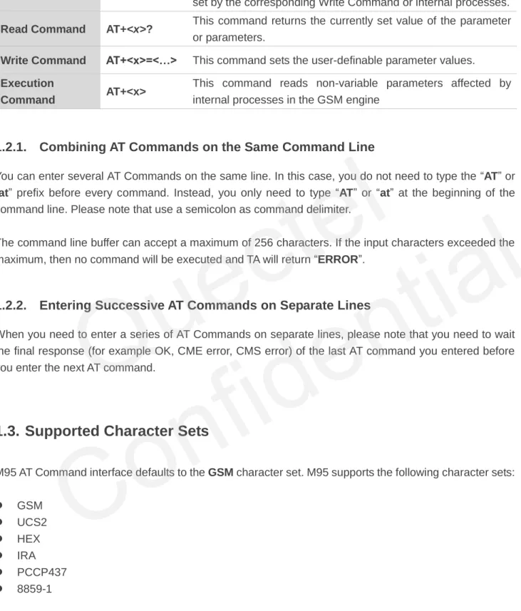
These commands can be operated in several modes, as following table:
Quectel
Table 1: Types of AT Commands and Responses
1.2.1. Combining AT Commands on the Same Command Line
You can enter several AT Commands on the same line. In this case, you do not need to type the “AT” or “at” prefix before every command. Instead, you only need to type “AT” or “at” at the beginning of the command line. Please note that use a semicolon as command delimiter.
The command line buffer can accept a maximum of 256 characters. If the input characters exceeded the maximum, then no command will be executed and TA will return “ERROR”.
1.2.2. Entering Successive AT Commands on Separate Lines
When you need to enter a series of AT Commands on separate lines, please note that you need to wait the final response (for example OK, CME error, CMS error) of the last AT command you entered before you enter the next AT command.
1.3. Supported Character Sets
M95 AT Command interface defaults to the GSM character set. M95 supports the following character sets:
GSM UCS2 HEX IRA PCCP437 8859-1
The character set can be configured and interrogated using the “AT+CSCS” command (GSM 07.07). The character set is defined in GSM specification 07.05. The character set affects transmission and reception of SMS and SMS Cell Broadcast Messages, the entry and display of phone book entries text field and SIM Application Toolkit alpha strings.
Test Command AT+<x>=? This command returns the list of parameters and value ranges
set by the corresponding Write Command or internal processes.
Read Command AT+<x>? This command returns the currently set value of the parameter
or parameters.
Write Command AT+<x>=<…> This command sets the user-definable parameter values.
Execution
Command AT+<x>
This command reads non-variable parameters affected by internal processes in the GSM engine
Quectel
1.4. Flow Control
Flow control is very important for correct communication between the GSM engine and DTE. For example, in the case such as a data or FAX call, the sending device is transferring data faster than the receiving side is ready to accept. When the receiving buffer reaches its capacity, the receiving device should be capable to cause the sending device to pause until it catches up.
There are basically two approaches to achieve data flow control: software flow control and hardware flow control. M95 supports both two kinds of flow control.
In Multiplex mode, it is recommended to use the hardware flow control. The default flow control approach of M95 is closed.
1.4.1. Software Flow Control (XON/XOFF Flow Control)
Software flow control sends different characters to stop (XOFF, decimal 19) and resume (XON, decimal 17) data flow. It is quite useful in some applications that only use three wires on the serial interface. The default flow control approach of M95 is closed, to enable software flow control in the DTE interface and within GSM engine, type the following AT command:
AT+IFC=1, 1<CR>
This setting is stored volatile, for use after restart, AT+IFC=1, 1<CR> should be stored to the user profile with AT&W<CR>.
Ensure that any communication software package (e.g. ProComm Plus, Hyper Terminal or WinFax Pro) uses software flow control.
Software Flow Control should not be used for data calls where binary data will be transmitted or received (e.g. TCP/IP), because the DTE interface may interpret binary data as flow control characters.
NOTE
Quectel
1.4.2. Hardware Flow Control (RTS/CTS Flow Control)
The default flow control approach of M95 is closed, to enable hardware flow control (RTS/CTS flow control) in the DTE interface and within GSM engine, type the following AT command:
AT+IFC=2, 2<CR>.
This setting is stored volatile, for use after restart, AT+IFC=2, 2<CR> should be stored to the user profile with AT&W<CR>.
Hardware flow control achieves the data flow control by controlling the RTS/CTS line. When the data transfer should be suspended, the CTS line is set inactive until the transfer from the receiving buffer has completed. When the receiving buffer is ok to receive more data, CTS goes active once again.
To achieve hardware flow control, ensure that the RTS/CTS lines are present on your application platform.
1.5. Unsolicited Result Code
A URC is a report message sent from the ME to the TE. An unsolicited result code can either be delivered automatically when an event occurs, to reflect change in system state or as a result of a query the ME received before, often due to occurrences of errors in executing the queries. However, a URC is not issued as a direct response to an executed AT command. AT commands have their own implementations to validate inputs such as “OK” or “ERROR”.
Typical URCs may be information about incoming calls, received SMS, changing temperature, status of the battery etc. A summary of URCs is listed in Appendix.
When sending a URC, the ME activates its Ring Interrupt (Logic “l”), i.e. the line goes active low for a few milliseconds. If an event which delivers a URC coincides with the execution of an AT command, the URC will be output after command execution has completed.
Quectel
2
General Commands
2.1. ATI Display Product Identification Information
Example
ATI Quectel_Ltd Quectel_M95 Revision: M95FAR01A01 OK2.2. AT+GMI Request Manufacturer Identification
ATI Display Product Identification Information
Execution Command ATI
Response
TA issues product information text. Quectel_Ltd
Quectel_M95
Revision: M95FARxxAxx OK
Maximum Response Time 300ms Reference
V.25ter
AT+GMI Request Manufacturer Identification
Test Command AT+GMI=? Response OK Execution Command AT+GMI Response
TA reports one or more lines of information text which permit the user to identify the manufacturer.
Quectel
2.3. AT+GMM Request TA Model Identification
2.4. AT+GMR Request TA Revision Identification of Software Release
Quectel_Ltd Quectel_M95
Revision: MTK 0828 OK
Maximum Response Time 300ms Reference
V.25ter
AT+GMM Request TA Model Identification
Test Command AT+GMM=? Response OK Execution Command AT+GMM Response
TA returns a product model identification text. Quectel_M95
OK Maximum Response Time 300ms Reference
V.25ter
AT+GMR Request TA Revision Identification of Software Release
Test Command AT+GMR=? Response OK Execution Command AT+GMR Response
TA reports one or more lines of information text which permit the user to identify the revision of software release.
Revision:<revision>
OK Maximum Response Time 300ms Reference
V.25ter
Quectel
Parameter
Example
AT+GMRRevision: M95FAR01A01 OK
2.5. AT+GOI Request Global Object Identification
Parameter
See X.208, 209 for the format of <Object Id>. For example, in M95 wireless module, string “M95” is
displayed.
<revision> Revision of software release
AT+GOI Request Global Object Identification
Test Command AT+GOI=? Response OK Execution Command AT+GOI Response
TA reports one or more lines of information text which permit the user to identify the device, based on the ISO system for registering unique object identifiers.
<Object Id> OK
Maximum Response Time 300ms Reference
V.25ter
<Object Id> Identifier of device type
NOTE
Quectel
2.6. AT+CGMI Request Manufacturer Identification
2.7. AT+CGMM Request Model Identification
Parameter
AT+CGMI Request Manufacturer Identification
Test Command AT+CGMI=? Response OK Execution Command AT+CGMI Response
TA returns manufacturer identification text. Quectel_Ltd
Quectel_M95
Revision: MTK 0828 OK
Maximum Response Time 300ms Reference
GSM 07.07
AT+CGMM Request Model Identification
Test Command AT+CGMM=? Response OK Execution Command AT+CGMM Response
TA returns product model identification text. <model>
OK Maximum Response Time 300ms Reference
GSM 07.07
<model> Product model identification text
Quectel
2.8. AT+CGMR Request TA Revision Identification of Software Release
Parameter
2.9. AT+GSN Request International Mobile Equipment Identity (IMEI)
Parameter
AT+CGMR Request TA Revision Identification of Software Release
Test Command AT+CGMR=? Response OK Execution Command AT+CGMR Response
TA returns product software version identification text. Revision: <revision>
OK Maximum Response Time 300ms Reference
GSM 07.07
<revision> Product software version identification text
AT+GSN Request International Mobile Equipment Identity (IMEI)
Test Command AT+GSN=? Response OK Execution Command AT+GSN Response
TA reports the IMEI (International Mobile Equipment Identity) number in information text which permit the user to identify the individual ME device.
<sn> OK Maximum Response Time 300ms Reference
V.25ter
<sn> IMEI of the telephone
Quectel
The serial number (IMEI) is varied with the individual ME device.
2.10. AT+CGSN Request Product Serial Number Identification (Identical
with +GSN)
See +GSN.
2.11. AT+QGSN Request Product Serial Number Identification (IMEI)
AT+CGSN Request Product Serial Number Identification (Identical with +GSN)
Test Command AT+CGSN=? Response OK Execution Command AT+CGSN Response <sn> OK Maximum Response Time 300ms Reference
GSM 07.07
AT+QGSN Request Product Serial Number Identification (IMEI)
Test Command AT+QGSN=? Response OK Execution Command AT+QGSN Response +QGSN: <sn> OK
Maximum Response Time 300ms Reference
GSM 07.07 NOTE
NOTE
Quectel
Parameter
The serial number (IMEI) is varied with the individual ME device.
Example
AT+QGSN //Query the IMEI
+QGSN: "359231033484583" OK
2.12. AT&F Set all Current Parameters to Manufacturer Defaults
Parameter
2.13. AT&V Display Current Configuration
<sn> A string parameter which indicates the IMEI of the telephone
AT&F Set all Current Parameters to Manufacturer Defaults
Execution Command AT&F[<value>]
Response
TA sets all current parameters to the manufacturer defined profile.
OK Maximum Response Time 300ms Reference
V.25ter
<value> 0 Set all TA parameters to manufacturer defaults
AT&V Display Current Configuration
Execution Command AT&V[<n>]
Response
TA returns the current parameter setting. ACTIVE PROFILE
NOTE
Quectel
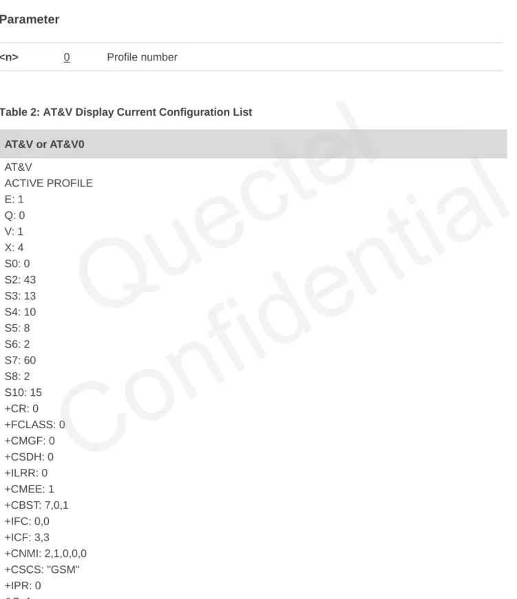
Parameter
Table 2: AT&V Display Current Configuration List AT&V or AT&V0 AT&V ACTIVE PROFILE E: 1 Q: 0 V: 1 X: 4 S0: 0 S2: 43 S3: 13 S4: 10 S5: 8 S6: 2 S7: 60 S8: 2 S10: 15 +CR: 0 +FCLASS: 0 +CMGF: 0 +CSDH: 0 +ILRR: 0 +CMEE: 1 +CBST: 7,0,1 +IFC: 0,0 +ICF: 3,3 +CNMI: 2,1,0,0,0 +CSCS: "GSM" +IPR: 0 &C: 1
<current configurations text> OK
Maximum Response Time 300ms Reference
V.25ter
<n> 0 Profile number
Quectel
&D: 0 +CSTA: 129 +CRLP: 61,61,128,6,0,3 +CCWE: 0 +QSIMSTAT: 0 +CMUX: -1 +CCUG: 0,10,0 +CLIP: 0 +COLP: 0 +CCWA: 0 +CAOC: 1 +CLIR: 0 +CUSD: 0 +CREG: 0 +QSIMDET: 0,0,0 +QMIC: 4,9,8 +QECHO(NORMAL_AUDIO): 253,96,16388,57351,0 +QECHO(Earphone_AUDIO): 253,0,10756,57351,1 +QECHO(LoudSpk_AUDIO): 224,96,5256,57351,2 +QSIDET(NORMAL_AUDIO): 80 +QSIDET(HEADSET_AUDIO): 144 +QCLIP: 0 +QCOLP: 0 +CSNS: 0 OK
2.14. AT&W Store Current Parameter to User Defined Profile
Parameter
AT&W Store Current Parameter to User Defined Profile
Execution Command AT&W[<n>]
Response
TA stores the current parameter setting in the user defined profile.
OK Maximum Response Time 300ms Reference
V.25ter
<n> 0 Profile number to store to
Quectel
The profile defined by user is stored in non-volatile memory.
2.15. ATQ Set Result Code Presentation Mode
Parameter
2.16. ATV TA Response Format
ATQ Set Result Code Presentation Mode
Execution Command ATQ<n>
Response
This parameter setting determines whether or not the TA transmits any result code to the TE. Information text transmitted in response is not affected by this setting.
If <n>=0: OK If <n>=1: (none) Maximum Response Time 300ms Reference
V.25ter
<n> 0 TA transmits result code
1 Result codes are suppressed and not transmitted
ATV TA Response Format
Execution Command ATV[<value>]
Response
This parameter setting determines the contents of the header and trailer transmitted with result codes and information responses.
When <value>=0
0
When <value>=1 OK
Maximum Response Time 300ms NOTE
Quectel
Parameter
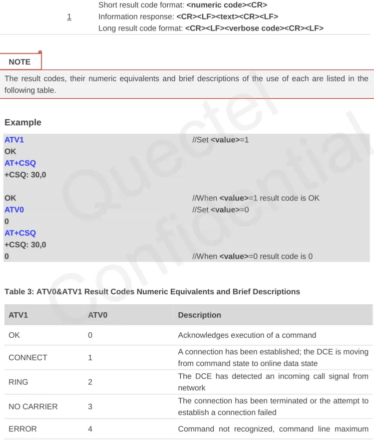
The result codes, their numeric equivalents and brief descriptions of the use of each are listed in the following table.
Example
ATV1 //Set <value>=1
OK AT+CSQ +CSQ: 30,0
OK //When <value>=1 result code is OK
ATV0 //Set <value>=0
0
AT+CSQ +CSQ: 30,0
0 //When <value>=0 result code is 0
Table 3: ATV0&ATV1 Result Codes Numeric Equivalents and Brief Descriptions
ATV1 ATV0 Description
OK 0 Acknowledges execution of a command
CONNECT 1 A connection has been established; the DCE is moving from command state to online data state
RING 2 The DCE has detected an incoming call signal from network
NO CARRIER 3 The connection has been terminated or the attempt to establish a connection failed
ERROR 4 Command not recognized, command line maximum Reference
V.25ter
<value> 0 Information response: <text><CR><LF>
Short result code format: <numeric code><CR> 1 Information response: <CR><LF><text><CR><LF>
Long result code format: <CR><LF><verbose code><CR><LF>
NOTE
Quectel
length exceeded, parameter value invalid, or other problem with processing the command line
NO DIALTONE 6 No dial tone detected
BUSY 7 Engaged (busy) signal detected
NO ANSWER 8
"@" (Wait for Quiet Answer) dial modifier was used, but remote ringing followed by five seconds of silence was not detected before expiration of the connection timer (S7)
PROCEEDING 9 An AT command is being processed
CONNECT <text> Manufacturer-specific
Same as CONNECT, but includes manufacturer-
specific text that may specify DTE speed, line speed, error control, data compression, or other status
2.17. ATX Set CONNECT Result Code Format and Monitor Call Progress
Parameter
ATX Set CONNECT Result Code Format and Monitor Call Progress
Execution Command ATX[<value>]
Response
This parameter setting determines whether or not the TA detected the presence of dial tone and busy signal and whether or not TA transmits particular result codes.
OK Maximum Response Time 300ms Reference
V.25ter
<value> 0 CONNECT result code only returned, dial tone and busy detection are both
disabled
1 CONNECT<text> result code only returned, dial tone and busy detection are
both disabled
2 CONNECT<text> result code returned, dial tone detection is enabled, busy
detection is disabled
3 CONNECT<text> result code returned, dial tone detection is disabled, busy
detection is enabled
4 CONNECT<text> result code returned, dial tone and busy detection are both
enabled
Quectel
1. If parameter is omitted, the command has the same behavior of ATX0. 2. The factory default is <value>=4.
2.18. ATZ Set all Current Parameters to User Defined Profile
Parameter
1. Profile defined by user is stored in non-volatile memory.
2. If the user profile is invalid, it will default to the factory default profile. 3. Any additional commands on the same command line are ignored.
2.19. AT+CFUN Set Phone Functionality
ATZ Set all Current Parameters to User Defined Profile
Execution Command ATZ[<value>]
Response
TA sets all current parameters to the user defined profile. OK
Maximum Response Time 300ms Reference
V.25ter
<value> 0 Reset to profile number 0
AT+CFUN Set Phone Functionality
Test Command AT+CFUN=?
Response
+CFUN: (list of supported <fun>s), (list of supported <rst>s)
OK Read Command AT+CFUN? Response +CFUN: <fun> OK NOTES NOTES
Quectel
Confidential
Parameter
Example
AT+CFUN=0 //Switch phone to minimum functionality
+CPIN: NOT READY OK
AT+COPS?
+COPS: 0 //No operator is registered
OK
AT+CPIN?
+CME ERROR: 13 //SIM failure
AT+CFUN=1 //Switch phone to full functionality
OK
+CPIN: SIM PIN AT+CPIN=1234 +CPIN: READY OK Call Ready AT+CPIN? +CPIN: READY Write Command AT+CFUN=<fun>[,<rst>] Response OK
If error is related to ME functionality: +CME ERROR: <err>
Maximum Response Time 15s, determined by network. Reference
GSM 07.07
<fun> 0 Minimum functionality
1 Full functionality (Default)
4 Disable phone both transmit and receive RF circuits
<rst> 0 Do not reset the ME before setting it to <fun> power level
This is default when <rst> is not given
1 Reset the ME before setting it to <fun> power level
Quectel
OK
AT+COPS?
+COPS: 0,0,"CHINA MOBILE" //Operator is registered
OK
2.20. AT+QPOWD Power off
Parameter
Example
AT+QPOWD=0OK //Urgent power off, returned OK
AT+QPOWD=1
NORMAL POWER DOWN //Normal power off, send out URC “NORMAL
POWER DOWN”
2.21. AT+CMEE Report Mobile Equipment Error
AT+QPOWD Power off
Write Command AT+QPOWD=<n> Response When <n>=0 OK When <n>=1
NORMAL POWER DOWN Maximum Response Time 300ms
Reference
<n> 0 Urgent power off ( Do not send out URC "NORMAL POWER DOWN")
1 Normal power off (Send out URC "NORMAL POWER DOWN")
AT+CMEE Report Mobile Equipment Error
Test Command AT+CMEE=?
Response
+CMEE: (list of supported <n>s)
OK
Quectel
Parameter
Example
AT+CMEE=0 //Disable result code
OK
AT+CPIN=1234
ERROR //Only “ERROR” will be displayed
AT+CMEE=1 //Enable error result code with numeric values
OK
AT+CPIN=1234 +CME ERROR: 10
AT+CMEE=2 //Enable error result code with verbose (string)
values OK
AT+CPIN=1234
+CME ERROR: SIM not inserted
2.22. AT+CSCS Select TE Character Set
Read Command AT+CMEE? Response +CMEE: <n> OK Write Command AT+CMEE=[<n>] Response
TA disables or enables the use of result code +CME ERROR:
<err> as an indication of an error related to the functionality of
the ME. OK Maximum Response Time 300ms Reference
GSM 07.07
<n> 0 Disable result code
1 Enable result code and use numeric values 2 Enable result code and use verbose values
AT+CSCS Select TE Character Set
Test Command AT+CSCS=?
Response
+CSCS: (list of supported <chset>s)
Quectel
Parameter
Example
AT+CSCS? //Query the current character set
+CSCS: "GSM" OK
AT+CSCS="UCS2" //Set the character set to “UCS2”
OK AT+CSCS? +CSCS: "UCS2" OK OK Read Command AT+CSCS? Response +CSCS: <chset> OK Write Command AT+CSCS=<chset> Response
Set character set <chset> which is used by the TE. The TA can then convert character strings correctly between the TE and ME character sets.
OK Maximum Response Time 300ms Reference
GSM 07.07
<chset> "GSM" GSM default alphabet
"HEX" Character strings consist only of hexadecimal numbers from 00 to FF "IRA" International reference alphabet
"PCCP437" PC character set Code "UCS2" UCS2 alphabet
"8859-1" ISO 8859 Latin 1 character set
Quectel
2.23. AT+GCAP Request Complete TA Capabilities List
Parameter
AT+GCAP Request Complete TA Capabilities List
Test Command AT+GCAP=? Response OK Execution Command AT+GCAP Response
TA reports a list of additional capabilities. +GCAP: <name>
OK Maximum Response Time 300ms Reference
V.25ter
<name> +CGSM GSM function is supported
+FCLASS FAX function is supported
Quectel
3
Serial Interface Control Commands
3.1. AT&C Set DCD Function Mode
Parameter
3.2. AT&D Set DTR Function Mode
AT&C Set DCD Function Mode
Execution Command AT&C[<value>]
Response
This parameter determines how the state of circuit 109 (DCD) relates to the detection of received line signal from the distant end.
OK Maximum Response Time 300ms Reference
V.25ter
<value> 0 DCD line is always ON
1 DCD line is ON only in the presence of data carrier
AT&D Set DTR Function Mode
Execution Command AT&D[<value>]
Response
This parameter determines how the TA responds when circuit 108/2(DTR) is changed from the ON to the OFF condition during data mode.
OK Maximum Response Time 300ms Reference
V.25ter
Quectel
Parameter
3.3. AT+ICF Set TE-TA Control Character Framing
Parameter
<value> 0 TA ignores status on DTR
1 ON->OFF on DTR: Change to command mode with remaining the connected call 2 ON->OFF on DTR: Disconnect data call, change to command mode. During state
DTR=OFF auto-answer is off
AT+ICF Set TE-TA Control Character Framing
Test Command AT+ICF=?
Response
+ICF: (list of supported <format>s), (list of supported
<parity>s) OK Read Command AT+ICF? Response +ICF: <format>,<parity> OK Write Command AT+ICF=[<format>,[<parity>]] Response
This parameter setting determines the serial interface character framing format and parity received by TA from TE. OK
Maximum Response Time 300ms Reference
V.25ter
<format> 1 8 data 0 parity 2 stop
2 8 data 1 parity 1 stop 3 8 data 0 parity 1 stop 4 7 data 0 parity 2 stop 5 7 data 1 parity 1 stop 6 7 data 0 parity 1 stop
<parity> 0 Odd 1 Even 2 Mark (1) 3 Space (0)
Quectel
Confidential
1. The command is applied for command state.
2. The <parity> field is ignored if the <format> field specifies no parity.
3.4. AT+IFC Set TE-TA Local Data Flow Control
Parameter
AT+IFC Set TE-TA Local Data Flow Control
Test Command AT+IFC=?
Response
+IFC: (list of supported <dce_by_dte>s), (list of supported
<dte_by_dce>s) OK Read Command AT+IFC? Response +IFC: <dce_by_dte>,<dte_by_dce> OK Write Command AT+IFC=<dce_by_dte>,<dte_by_dce> Response
This parameter setting determines the data flow control on the serial interface for data mode.
OK Maximum Response Time 300ms Reference
V.25ter
<dce_by_dte> Specifies the method will be used by TE when receiving data from TA
0 None
1 XON/XOFF, do not pass characters on to data stack 2 RTS flow control
3 XON/XOFF, pass characters on to data stack
<dte_by_dce> Specifies the method will be used by TA when receiving data from TE
0 None 1 XON/XOFF 2 CTS flow control NOTES
Quectel
Confidential
This flow control is applied for data mode.
Example
AT+IFC=2,2 //Open the hardware flow control
OK AT+IFC? +IFC: 2,2 OK
3.5. AT+ILRR Set TE-TA Local Data Rate Reporting Mode
Parameter
AT+ILRR Set TE-TA Local Data Rate Reporting Mode
Test Command AT+ILRR=?
Response
+ILRR: (list of supported <value>s)
OK Read Command AT+ILRR? Response +ILRR: <value> OK Write Command AT+ILRR=[<value>] Response
This parameter setting determines whether or not an intermediate result code of local rate is reported when the connection is established. The rate is applied after the final result code of the connection is transmitted to TE.
OK Maximum Response Time 300ms Reference
V.25ter
<value> 0 Disables reporting of local port rate
1 Enables reporting of local port rate NOTE
Quectel
If the <value> is set to 1, the following intermediate result will come out on connection to indicate the port rate settings.
+ILRR:<rate>
<rate> Port rate setting on call connection in Baud per second
300 1200 2400 4800 9600 14400 19200 28800 38400 57600 115200
3.6. AT+IPR Set TE-TA Fixed Local Rate
AT+IPR Set TE-TA Fixed Local Rate
Test Command AT+IPR=?
Response
+IPR: (list of supported auto detectable <rate>s),(list of
supported fixed-only<rate>s) OK Read Command AT+IPR? Response +IPR: <rate> OK Write Command AT+ IPR=<rate> Response
This parameter setting determines the data rate of the TA on the serial interface. After the delivery of any result code associated with the current command line, the rate of command takes effect.
OK Maximum Response Time 300ms Reference
V.25ter NOTE
Quectel
Parameter
1. The default configuration of AT+IPR is adaptive baud enabled (AT+IPR=0).
2. If a fixed baud rate is set, make sure that both TE (DTE, usually external processor) and TA (DCE, Quectel GSM module) are configured to the same rate. If adaptive baud is enabled, the TA could automatically recognize the baud rate currently used by the TE after receiving “AT” or “at” string. 3. The value of AT+IPR cannot be restored with AT&F and ATZ, but it is still storable with AT&W and
visible in AT&V.
4. In multiplex mode, the baud rate cannot be changed by the write command AT+IPR=<rate>, and the setting is invalid and not stored even if AT&W is executed after the write command.
5. A selected baud rate takes effect after the write commands are executed and acknowledged by “OK”.
Example
AT+IPR=115200 //Set fixed baud rate to 115200
OK
AT&W //Store current setting, that is, the serial
communication speed is 115200 after restart module
OK AT+IPR? +IPR: 115200 OK
<rate> Baud rate per second
0 (Autobauding) 75 150 300 600 1200 2400 4800 9600 14400 19200 28800 38400 57600 115200 NOTES
Quectel
Confidential
3.6.1. Adaptive Baud
To take advantage of adaptive baud mode, specific attention must be paid to the following requirements: 1. Adaptive baud synchronization between TE and TA.
Ensure that TE and TA are correctly synchronized and the baud rate used by the TE is detected by the TA. To allow the baud rate to be synchronized simply use an “AT” or “at” string. This is necessary after customer activates adaptive baud or when customer starts up the module with adaptive baud enabled.
It is recommended to wait for 2 to 3 seconds before sending the first “AT” or “at” string after the module is started up with adaptive baud enabled. Otherwise undefined characters might be returned.
2. Restriction on adaptive baud operation.
The serial interface shall be used with 8 data bits, no parity and 1 stop bit (factory setting).
The command “A/” can’t be used.
Only the string “AT” or “at” can be detected (either “AT” or “at”).
URCs that may be issued before the TA detects a new baud rate by receiving the first AT character, and they will be sent at the previously detected baud rate.
If TE’s baud rate is changed after TA has recognized the earlier baud rate, loss of synchronization between TE and TA would be encountered and an “AT” or “at” string must be re-sent by TE to regain synchronization on baud rate. To avoid undefined characters during baud rate resynchronization and the possible malfunction of resynchronization, it is not recommended to switch TE’s baud rate when adaptive baud is enabled. Especially, this operation is forbidden in data mode.
3. Adaptive baud and baud rate after restarting.
In the adaptive baud mode, the detected baud rate is not saved. Therefore, resynchronization is required after restarting the module.
Unless the baud rate is determined, an incoming CSD call can’t be accepted. This must be taken into account when adaptive baud and auto-answer mode (ATS0≠0) are enabled at the same time, especially if SIM PIN 1 authentication is done automatically and the setting ATS0≠0 is stored to the user profile with AT&W.
Until the baud rate is synchronized, URCs after restarting will not be output when adaptive baud is enabled.
4. Adaptive baud and multiplex mode.
If adaptive baud is active it is not recommended to switch to multiplex mode. 5. Adaptive baud and Windows modem.
The baud rate used by Windows modem can be detected while setting up a dial-up GPRS/CSD connection. However, some Windows modem drivers switch TE’s baud rate to default value automatically after the GPRS call is terminated. In order to prevent no response to the Windows
Quectel
modem when it happens, it is not recommended to establish the dial-up GPRS/CSD connection in adaptive baud mode.
Based on the same considerations, it is also not recommended to establish the FAX connection in adaptive baud mode for PC FAX application, such as WinFax.
To assure reliable communication and avoid any problem caused by undetermined baud rate between DCE and DTE, it is strongly recommended to configure a fixed baud rate and save it instead of using adaptive baud after start-up.
3.7. AT+CMUX Multiplexer Control
Parameter
AT+CMUX Multiplexer Control
Test Command AT+CMUX=?
Response
+CMUX: (list of supported <mode>s), (<subset>s),
(<port_speed>s),(<N1>s),(<T1>s),(<N2>s),(<T2>s),(<T3>s), (<k>s) OK Read Command AT+CMUX? Response +CMUX:<mode>,0,5,127,10,3,30,10,2 OK ERROR Write Command AT+CMUX=[<mode>[,<subset>[,<port _speed>[,<N1>[,<T1>[,<N2>[,<T2>[,<T 3>[,<k>]]]]]]]]] Response
+CME ERROR: <err>
Maximum Response Time 300ms Reference
GSM 07.07
<mode> Multiplexer transparency mechanism
0 Basic option
<subset> The way by which the multiplexer control channel is set up
0 UIH frames used only
<port_speed> Transmission rate
NOTE
Quectel
1. Advanced option with Error Recovery options is not supported.
2. The multiplexing transmission rate is fixed according to the current serial baud rate. It is recommended to enable multiplexing protocol under 115200 bit/s baudrate.
3. Multiplexer control channels are listed as follows:
Channel Number Type DLCI
None Multiplexer Control 0 1 07.07 and 07.05 1 2 07.07 and 07.05 2 3 07.07 and 07.05 3 4 07.07 and 07.05 4
5 115200bit/s
<N1> Maximum frame size
127
<T1> Acknowledgement timer in a unit of ten milliseconds
10
<N2> Maximum number of re-transmissions
3
<T2> Response timer for the multiplexer control channel in a unit of ten milliseconds
30
<T3> Wake up response timers in seconds
10
<k> Window size, for Advanced operation with Error Recovery options
2
NOTES
Quectel
4
Status Control Commands
4.1. AT+CEER Extended Error Report
Parameter
Example
AT+CEER //Query error reporting in normal state, return “No error”
+CEER: 0,0 OK ATD10086; OK AT+CLCC +CLCC: 1,0,0,0,0,"10086",129,""
AT+CEER Extended Error Report
Test Command AT+CEER=? Response OK Execution Command AT+CEER Response
TA returns an extended report of the reason for the last call release.
+CEER: <locationID>,<cause> OK
Maximum Response Time 300ms Reference
GSM 07.07
<locationID> Location ID as number code. Location IDs are listed in Section 8.3.1.
Each ID is related with anther table that contains a list of <cause>s.
<cause> Reason for last call release as number code. The number codes are listed in
several tables, sorted by different categories. The tables can be found proceeding from the Location ID given in Section 8.3.1
Quectel
OK
NO CARRIER //Established a call and the remote party hangs up the call
AT+CEER //Query error reporting, the <locationID>=1 means “Cause
for protocol stack (PS) layer”, <cause>=16 means “Normal call clearing”
+CEER: 1,16 OK
4.2. AT+CPAS Mobile Equipment Activity Status
Parameter
Example
AT+CPAS+CPAS: 0 //Module is idle
AT+CPAS Mobile Equipment Activity Status
Test Command AT+CPAS=?
Response
+CPAS: (list of supported <pas>s)
OK Execution Command
AT+CPAS
Response
TA returns the activity status of ME. +CPAS: <pas>
OK
If error is related to ME functionality: +CME ERROR: <err>
Maximum Response Time 300ms Reference
GSM 07.07
<pas> 0 Ready
2 Unknown (ME is not guaranteed to respond to instructions) 3 Ringing
4 Call in progress or call hold
Quectel
OK ATD10086; OK AT+CLCC +CLCC: 1,0,3,0,0,"10086",129,"" OK AT+CPAS
+CPAS: 3 //Module is incoming call (ringing)
OK AT+CLCC
+CLCC: 1,0,0,0,0,"10086",129,"" OK
AT+CPAS
+CPAS: 4 //Call in progress
OK
4.3. AT+QINDRI Indicate RI When Using URC
AT+QINDRI Indicate RI When Using URC
Test Command AT+QINDRI=?
Response
+QINDRI: (list of supported <status>s)
OK Read Command AT+QINDRI? Response +QINDRI:<status> OK Write Command AT+QINDRI=<status> Response OK ERROR Maximum Response Time 300ms Reference
Quectel
Parameter
4.4. AT+QMOSTAT Show State of Mobile Originated Call
Parameter
Example
AT+QMOSTAT=1 //Show call state of mobile originated call
OK
ATD10086; OK
MO RING //The other call side is alerted
MO CONNECTED //The call is established
<status> 0 Off
1 On
AT+QMOSTAT Show State of Mobile Originated Call
Test Command AT+QMOSTAT=?
Response
+QMOSTAT: (list of supported <mode>s)
OK Read Command AT+QMOSTAT? Response +QMOSTAT:<mode> OK Write Command AT+QMOSTAT=<mode> Response OK ERROR Maximum Response Time 300ms Reference
<mode> 0 Do not show call state of mobile originated call
1 Show call state of mobile originated call. After dialing call numbers, the URC strings of MO RING will be sent if the other call side is alerted and the URC strings
of MO CONNECTED will be sent if the call is established
Quectel
4.5. AT+QIURC Enable or Disable Initial URC Presentation
Parameter
When the module powers on and initialization procedure is over. URC "Call Ready" will be presented if <mode> is 1.
4.6. AT+QEXTUNSOL Enable/Disable Proprietary Unsolicited
Indications
AT+QIURC Enable or Disable Initial URC Presentation
Test Command AT+QIURC=?
Response
+QIURC: (list of supported <mode>s)
OK Read Command AT+QIURC? Response +QIURC: <mode> OK Write Command AT+QIURC=<mode> Response OK ERROR Maximum Response Time 300ms Reference
<mode> 0 Disable URC presentation
1 Enable URC presentation
AT+QEXTUNSOL Enable/Disable Proprietary Unsolicited Indications
Test Command AT+QEXTUNSOL=?
Response
+QEXTUNSOL: (list of supported <extunsol>s)
OK Write Command AT+QEXTUNSOL=<exunsol>,<mode> Response OK NOTE
Quectel
Confidential
Parameter
ERROR Maximum Response Time 300ms Reference
<extunsol> String type. Values currently reserved by the present document
"SQ" Signal Quality Report. Displays signal strength and channel bit error rate (similar to AT+CSQ) in form +CSQN: <rssi>, <ber>when values change.
"FN" Forbidden network available only. When returning to a non-registered state, this indicates whether all the available PLMNs are forbidden.
"MW" SMS Message waiting. On receiving an SMS (as indicated by the +CMTI indication) the SMS is decoded and checked to see if it contains one or more of the message waiting indications (i.e. voicemail, email, fax etc). If so, an unsolicited indication is shown in the form for each message type:
+QMWT: <store>,<index>,<voice>,<fax>,<email>,<other>. Where <store> is the message store containing the SM, index is the message index and <voice>,
<email>, <fax>, <other> contain the number of waiting messages (with ‘0’
defined as clear indication, non-zero for one or more waiting messages) or blank for not specified in this message.
"UR" Unsolicited result code. Produces an unsolicited indication in the following call state transition. Multiple notifications may occur for the same transition +QGURC:
<event>. Where <event> describes the current call state:
<event>:
0 Terminated active call, at least one held call remaining 1 Attempt to make an Mobile Originated call
2 Mobile Originated Call has failed for some reason 3 Mobile Originated call is ringing
4 Mobile Terminated call is queued (Call waiting) 5 Mobile Originated Call now has been connected
6 Mobile Originated or Mobile Terminated call has been disconnected 7 Mobile Originated or Mobile Terminated call hung up.
8 Mobile Originated call dialed a non-emergency number in emergency mode
9 No answer for Mobile Originated Call
10 Remote number busy for Mobile Originated Call
"BC" Battery Charge. Displays battery connection status and battery charge level (similar to AT+CBC) in form +CBCN:<bcs>,<bcl> when values change.
"BM" Band mode. Displays band mode (similar to AT+QBAND) in form +QBAND:
<band> when value changes.
"SM" Additional SMS Information. Displays additional information about SMS events in
Quectel
4.7. AT+QINISTAT Query State of Initialization
Parameter
When <state> is 3, it also means initialization of SIM card related functions has finished.
the form of Unsolicited messages of the following format +TSMSINFO: <CMS
error info> where <CMS error info> is a standard CMS error in the format
defined by the AT+CMEE command i.e. either a number or a string.
"CC" Call information. Displays the disconnected call ID and the remaining call numbers after one of the call is disconnected. +CCINFO: <Call id disconnected>,<Remain calls>
<mode> 0 Disable
1 Enable 2 Query
AT+QINISTAT Query State of Initialization
Test Command AT+QINISTAT=? Response OK Execution Command AT+QINISTAT Response +QINISTAT: <state> OK
Maximum Response Time 300ms Reference
<state> 0 No initialization
1 Ready to execute AT command 2 Phonebook has finished initialization 3 SMS has finished initialization
NOTE
Quectel
4.8. AT+QNSTATUS Query GSM Network Status
Parameter
4.9. AT+QNITZ Network Time Synchronization
AT+QNSTATUS Query GSM Network Status
Test Command AT+QNSTATUS=? Response OK Execution Command AT+QNSTATUS Response +QNSTATUS: <status> OK
If error is related to ME functionality: +CME ERROR: <err>
Maximum Response Time 300ms Reference
<status> 255 Not ready to retrieve network status
0 Work in normal state 1 No available cell
2 Only limited service is available
AT+QNITZ Network Time Synchronization
Test Command AT+QNITZ=?
Response
+QNITZ: (list of supported <enable>s)
OK Read Command AT+QNITZ? Response +QNITZ:<enable> OK Write Command AT+QNITZ=<enable> Response OK
If error is related to ME functionality: +CME ERROR: <err>
Quectel
Parameter
This function needs support of local GSM network. And the unsolicited also can be read by AT+QLTS command later.
4.10. AT+QLTS Obtain Latest Network Time Synchronized
Maximum Response Time 300ms Reference
<enable> 0 Disable to synchronize time from GSM network
1 Enable to synchronize time from GSM network
If the function is enabled, on receiving network time message, an unsolicited indication is shown in the form: “+QNITZ: <time>,<ds>”
<time> String type value. Format is "yy/MM/dd,hh:mm:ss±zz,ds", where characters indicate
year (two last digits), month, day, hour, minutes, seconds and time zone (indicates the difference, expressed in quarters of an hour, between the local time and GMT; range: -47...+48). E.g. 6th of May 2004, 22:10:00 GMT+2 hours
<ds> Daylight Saving Time. It is zero equal to "04/05/06,22:10:00+08,0"
AT+QLTS Obtain Latest Network Time Synchronized
Test Command AT+QLTS=? Response OK Execution Command AT+QLTS Response +QLTS: <time>,<ds> OK
If error is related to ME functionality: +CME ERROR: <err>
Execution Command returns latest time for Network synchronization.
Maximum Response Time 300ms Reference
NOTE
Quectel
Parameter
4.11. AT+CTZU Network Time Synchronization and Update the RTC
Time
Parameter
<time> String type value. Format is "yy/MM/dd,hh:mm:ss±zz", where characters indicate
year (two last digits), month, day, hour, minutes, seconds and time zone (indicates the difference, expressed in quarters of an hour, between the local time and GMT; range: -47...+48). E.g. 6th of May 2004, 22:10:00 GMT+2 hours.
<ds> Daylight Saving Time. It is zero equals to "04/05/06,22:10:00+08,0"
AT+CTZU Network Time Synchronization and Update the RTC Time
Test Command AT+CTZU=?
Response
+CTZU: (list of supported <mode>s)
OK Read Command AT+CTZU? Response +CTZU:<mode> OK Write Command AT+CTZU=<mode> Response OK
If error is related to ME functionality: +CME ERROR: <err>
Maximum Response Time 300ms Reference
<mode> 0 Disable automatic update RTC time via NITZ.
1 Update network synchronized time to RTC and save time zone into NVRAM. 2 Update GMT time with