BRITISH STANDARD
BS EN
1997-2:2007
Eurocode 7 —
Geotechnical design —
Part 2: Ground investigation and
testing
The European Standard EN 1997-2:2007 has the status of a British Standard
ICS 91.060.01; 91.120.20
This British Standard was published under the authority of the Standards Policy and Strategy Committee on 30 April 2007
© BSI 2007
National foreword
This British Standard was published by BSI. It is the UK implementation of EN 1997-2:2007. It supersedes DD ENV 1997-2:2000 and DD ENV 1997-3:2000 which are withdrawn. It partially supersedes BS 5930:1999 and
BS 1377-9:1990.
The structural Eurocodes are divided into packages by grouping Eurocodes for each of the main materials: concrete, steel, composite concrete and steel, timber, masonry and aluminium; this is to enable a common date of
withdrawal (DOW) for all the relevant parts that are needed for a particular design. The conflicting national standards will be withdrawn at the end of the coexistence period, after all the EN Eurocodes of a package are available. Following publication of the EN, there is a period allowed for national calibration during which the National Annex is issued, followed by a
coexistence period of a maximum three years. During the coexistence period Member States are encouraged to adapt their national provisions. At the end of this coexistence period, the conflicting parts of national standard(s) will be withdrawn.
In the UK, the primary corresponding national standard is:
— BS 5930:1999, Code of practice for site investigations
and based on this transition period, this standard will be withdrawn/revised on a date to be announced, but at the latest by March 2010.
For in-situ testing, the primary test method references in BS EN 1997-2:2007 are to new CEN /ISO standards and this will require the withdrawal of some sections of BS 1377-9:1990, Methods of test for soils for civil engineering purposes — In-situ tests, as well as parts of BS 5930:1999 as they are published.
For laboratory testing, many of the primary test method references in
BS EN 1997-2:2007 are new CEN/ISO technical specifications. These will not be adopted in the UK and the standards below will continue to be the preferred standards.
— BS 1377-1:1990, Methods of test for soils for civil engineering purposes –
General requirements and sample preparation
— BS 1377-2:1990, Methods of test for soils for civil engineering purposes –
Classification tests
— BS 1377-3:1990, Methods of test for soils for civil engineering purposes –
Chemical and electro-chemical tests
— BS 1377-4:1990, Methods of test for soils for civil engineering purposes –
Compaction-related tests
— BS 1377-5:1990, Methods of test for soils for civil engineering purposes –
Compressibility, permeability and durability tests
— BS 1377-6:1990, Methods of test for soils for civil engineering purposes –
Consolidation and permeability tests in hydraulic cells and with pore pressure measurement
— BS 1377-7:1990, Methods of test for soils for civil engineering purposes –
Shear strength tests (total stress)
— BS 1377-8:1990, Methods of test for soils for civil engineering purposes –
Shear strength tests (effective stress) Amendments issued since publication
Amd. No. Date Comments
Further guidance will be given in the National Annex to EN 1997-2.
The UK participation in its preparation was entrusted to Technical Committee B/526, Geotechnics.
A list of organizations represented on this committee can be obtained on request to its secretary.
Where a normative part of this EN allows for a choice to be made at the national level, the range and possible choice will be given in the normative text, and a note will qualify it as a Nationally Determined Parameter (NDP). NDPs can be a specific value for a factor, a specific level or class, a particular method or a particular application rule if several are proposed in the EN.
To enable EN 1997-2 to be used in the UK, the NDPs will be published in a National Annex, which will be made available by BSI in due course, after public consultation has taken place.
This publication does not purport to include all the necessary provisions of a contract. Users are responsible for its correct application.
Compliance with a British Standard cannot confer immunity from legal obligations.
EUROPEAN STANDARD
NORME EUROPÉENNE
EUROPÄISCHE NORM
EN 1997-2
March 2007
ICS 91.060.01; 91.120.20 Supersedes ENV 1997-2:1999, ENV 1997-3:1999
English Version
Eurocode 7 - Geotechnical design - Part 2: Ground investigation
and testing
Eurocode 7 - Calcul géotechnique - Partie 2:
Reconnaissance des terrains et essais Eurocode 7 - Entwurf, Berechnung und Bemessung in derGeotechnik - Teil 2: Erkundung und Untersuchung des Baugrunds
This European Standard was approved by CEN on 12 June 2006.
CEN members are bound to comply with the CEN/CENELEC Internal Regulations which stipulate the conditions for giving this European Standard the status of a national standard without any alteration. Up-to-date lists and bibliographical references concerning such national standards may be obtained on application to the CEN Management Centre or to any CEN member.
This European Standard exists in three official versions (English, French, German). A version in any other language made by translation under the responsibility of a CEN member into its own language and notified to the CEN Management Centre has the same status as the official versions.
CEN members are the national standards bodies of Austria, Belgium, Bulgaria, Cyprus, Czech Republic, Denmark, Estonia, Finland, France, Germany, Greece, Hungary, Iceland, Ireland, Italy, Latvia, Lithuania, Luxembourg, Malta, Netherlands, Norway, Poland, Portugal, Romania, Slovakia, Slovenia, Spain, Sweden, Switzerland and United Kingdom.
EUROPEAN COMMITTEE FOR STANDARDIZATION C O M I T É E U R O P É E N D E N O R M A L I S A T I O N E U R O P Ä I S C H E S K O M I T E E F Ü R N O R M U N G
Management Centre: rue de Stassart, 36 B-1050 Brussels
© 2007 CEN All rights of exploitation in any form and by any means reserved Ref. No. EN 1997-2:2007: E
Contents ... Page Foreword ... 7 Section 1 General... 10 1.1 Scope ... 10 1.1.1 Scope of Eurocode 7 ... 10 1.1.2 Scope of EN 1997-2... 10 1.2 Normative references... 11 1.3 Assumptions ... 12
1.4 Distinction between Principles and Application Rules ... 12
1.5 Definitions ... 13
1.5.1 Terms common to all Eurocodes ... 13
1.5.2 Terms common to Eurocode 7... 13
1.5.3 Specific definitions used in EN 1997-2 ... 13
1.6 Test results and derived values... 14
1.7 The link between EN 1997-1 and EN 1997-2 ... 15
Section 2 Planning of ground investigations ... 20
2.1 Objectives ... 20
2.1.1 General... 20
2.1.2 Ground ... 21
2.1.3 Construction materials ... 22
2.1.4 Groundwater ... 22
2.2 Sequence of ground investigations ... 22
2.3 Preliminary investigations ... 23
2.4 Design investigations... 24
2.4.1 Field investigations ... 24
2.4.2 Laboratory tests... 27
2.5 Controlling and monitoring ... 31
Section 3 Soil and rock sampling and groundwater measurements ... 33
3.1 General... 33
3.2 Sampling by drilling ... 33
3.3 Sampling by excavation... 33
3.4 Soil sampling ... 33
3.4.1 Categories of sampling methods and laboratory quality classes of samples ... 33
3.4.2 Soil identification... 34
3.4.3 Planning of soil sampling... 34
3.4.4 Handling, transport and storing of samples ... 35
3.5 Rock sampling ... 35
3.5.1 Categories of sampling methods... 35
3.5.2 Rock identification... 36
3.5.3 Planning of rock sampling ... 36
3.5.4 Handling, transport and storing of samples ... 37
3.6 Groundwater measurements in soils and rocks ... 37
3.6.1 General... 37
3.6.2 Planning and execution of the measurements... 37
3.6.3 Evaluation of results of groundwater measurements ... 38
Section 4 Field tests in soil and rock ... 40
4.1 General... 40
4.2 General requirements... 40
4.2.1 Planning a specific test programme ... 40
4.2.2 Execution ... 41
4.2.3 Evaluation ... 41
4.3 Cone penetration and piezocone penetration tests (CPT, CPTU)... 42
4.3.1 Objectives ... 42
4.3.2 Specific requirements... 42
4.3.3 Evaluation of test results... 43
4.3.4 Use of test results and derived values ... 43
4.4 Pressuremeter tests (PMT)... 45
4.4.1 Objectives ... 45
4.4.2 Specific requirements... 45
4.4.3 Evaluation of test results... 46
4.4.4 Use of test results and derived values ... 47
4.5 Flexible dilatometer test (FDT) ... 48
4.5.1 Objectives ... 48
4.5.2 Specific requirements... 48
4.5.3 Evaluation of test results... 48
4.5.4 Use of test results and derived values ... 49
4.6 Standard penetration test (SPT)... 49
4.6.1 Objectives ... 49
4.6.2 Specific requirements... 49
4.6.3 Evaluation of test results... 49
4.6.4 Use of test results and derived values ... 50
4.7 Dynamic probing tests (DP) ... 51
4.7.1 Objectives ... 51
4.7.2 Specific requirements... 52
4.7.3 Evaluation of test results... 52
4.7.4 Use of test results and derived values ... 52
4.8 Weight sounding test (WST) ... 53
4.8.1 Objectives ... 53
4.8.2 Specific requirements... 53
4.8.3 Evaluation of test results... 54
4.8.4 Use of test results and derived values ... 54
4.9 Field vane test (FVT)... 55
4.9.1 Objectives ... 55
4.9.2 Specific requirements... 55
4.9.3 Evaluation of test results... 55
4.9.4 Use of test results and derived values ... 55
4.10 Flat dilatometer test (DMT)... 56
4.10.1 Objectives ... 56
4.10.2 Specific requirements... 56
4.10.3 Evaluation of test results... 56
4.10.4 Use of test results and derived values ... 57
4.11 Plate loading test (PLT)... 57
4.11.1 Objectives ... 57
4.11.2 Specific requirements... 58
4.11.3 Evaluation of test results... 58
4.11.4 Use of test results and derived values ... 58
Section 5 Laboratory tests on soil and rock ... 60
5.1 General... 60
5.2 General requirements for laboratory tests ... 60
5.2.1.General requirements ... 60
5.2.2 Procedures, equipment and presentation... 60
5.2.3 Evaluation of test results... 60
5.3 Preparation of soil specimens for testing... 61
5.3.1 Objective ... 61
5.3.2 Requirements ... 61
5.4 Preparation of rock specimens for testing ... 62
5.4.1 Objective ... 62
5.4.2 Requirements ... 62
5.5 Tests for classification, identification and description of soil ... 63
5.5.1 General... 63
5.5.2 Requirements for all classification tests ... 63
5.5.3 Water content determination... 63
5.5.4 Bulk density determination ... 64
5.5.5 Particle density determination... 64
5.5.6 Particle size analysis ... 64
5.5.7 Consistency limits determination... 65
5.5.8 Determination of the density index of granular soil ... 66
5.5.9 Soil dispersibility determination ... 67
5.5.10 Frost susceptibility ... 68
5.6 Chemical testing of soil and groundwater ... 68
5.6.1 Requirements for all chemical tests ... 68
5.6.2 Organic content determination... 70
5.6.3 Carbonate content determination ... 71
5.6.4 Sulfate content determination ... 71
5.6.5 pH value determination (acidity and alkalinity) ... 72
5.6.6 Chloride content determination... 72
5.7 Strength index testing of soil ... 73
5.7.1 Objective ... 73
5.7.2 Requirements ... 73
5.7..3 Use of test results ... 73
5.8 Strength testing of soil... 73
5.8.1 Objective and scope ... 73
5.8.2 General requirements ... 74
5.8.3 Evaluation and use of test results... 75
5.8.4 Unconfined compression test... 75
5.8.5 Unconsolidated, undrained triaxial compression test ... 76
5.8.6 Consolidated triaxial compression test ... 76
5.8.7 Consolidated direct shear box tests... 77
5.9 Compressibility and deformation testing of soil... 78
5.9.1 General... 78
5.9.2 Oedometer compressibility testing ... 78
5.9.3 Triaxial deformability testing ... 80
5.10 Compaction testing of soil... 81
5.10.1 Scope... 81
5.10.2 Compaction tests... 81
5.10.3 California Bearing ratio (CBR) test ... 81
5.11 Permeability testing of soil ... 82
5.11.1 Objective ... 82
5.11.2 Requirements ... 82
5.11.3 Evaluation and use of test results... 83
5.12 Tests for classification of rocks ... 84
5.12.1 General... 84
5.12.2 Requirements for all classification tests ... 84
5.12.3 Rock identification and description ... 84
5.12.4 Water content determination... 85
5.12.5 Density and porosity determination ... 86
5.13 Swelling testing of rock material... 86
5.13.1 General... 86
5.13.2 General requirements ... 87
5.13.3 Evaluation of test results... 87
5.13.4 Swelling pressure index under zero volume change... 87
5.13.5 Swelling strain index for radially-confined specimens with axial surcharge ... 88
5.13.6 Swelling strain developed in unconfined rock specimen... 89
5.14 Strength testing of rock material ... 89
5.14.1 General... 89
5.14.2 Requirements for all strength tests... 89
5.14.3 Evaluation of test results... 90
5.14.4 Uniaxial compression and deformability test ... 90
5.14.5 Point load test... 91
5.14.6 Direct shear test... 92
5.14.7 Brazil test ... 93
5.14.8 Triaxial compression test ... 94
Section 6 Ground investigation report ... 95
6.1 General requirements... 95
6.2 Presentation of geotechnical information ... 95
6.3 Evaluation of geotechnical information ... 96
6.4 Establishment of derived values ... 97
Annex A (informative) List of test results of geotechnical test standards... 98
Annex B (informative) Planning of geotechnical investigations...101
Annex C (informative) Example of groundwater pressure derivations based on a model and long term measurements...109
Annex D (informative) Cone and piezocone penetration tests...111
Annex E (informative) Pressure meter test...121
Annex F (informative) Standard penetration test...125
Annex G (informative) Dynamic probing test...129
Annex H (informative) Weight sounding test 134 Annex I (informative) Field vane test...133
Annex J (informative) Flat dilatometer test Example of correlations between EOED and DMT results...138
Annex K (informative) Plate loading test...139
Annex L (informative) Detailed information on preparation of soil specimens for testing...143
Annex M (informative) Detailed information on tests for classification, identification and description of soil... 150
Annex N (informative) Detailed information on chemical testing of soil... 157
Annex O (informative) Detailed information on strength index testing of soil...162
Annex P (informative) Detailed information on strength testing of soil...163
Annex Q (informative) Detailed information on compressibility testing of soil ... 165
Annex R (informative) Detailed information on compaction testing of soil ... 166
Annex S (informative) Detailed information on permeability testing of soil ... 168
Annex T (informative) Preparation of specimen for testing on rockmaterial...170
Annex U (informative) Classification testing of rock material ... 171
Annex V (informative) Swelling testing of rock material ... 173
Annex W (informative) Strength testing of rock material ... 175
Annex X (informative) Bibliography... 180
Foreword
This document (EN 1997-2: 2007) has been prepared by Technical Committee CEN/TC 250 "Structural Eurocodes", the secretariat of which is held by BSI.
This European Standard shall be given the status of a national standard, either by publication of
an identical text or by endorsement, at the latest by September 2007, and conflicting national standards
shall be withdrawn at the latest by March 2010.
This document supersedes ENV 1997-2:1999 and ENV 1997-3:1999. CEN/TC 250 is responsible for all Structural Eurocodes.
According to the CEN/CENELEC Internal Regulations, the national standards organizations of the following countries are bound to implement this European Standard: Austria, Belgium, Bulgaria
Cyprus, Czech Republic, Denmark, Estonia, Finland, France, Germany, Greece, Hungary, Iceland, Ireland, Italy, Latvia, Lithuania, Luxembourg, Malta, Netherlands, Norway, Portugal, Poland, Romania, Slovakia, Slovenia, Spain, Sweden, Switzerland and the United Kingdom.
Background of the Eurocode programme
In 1975, the Commission of the European Community decided on an action programme in the field of construction, based on article 95 of the Treaty. The objective of the programme was the elimination of technical obstacles to trade and the harmonization of technical specifications. Within this action programme, the Commission took the initiative to establish a set of
harmonised technical rules for the design of construction works, which, in a first stage, would serve as an alternative to the national rules in force in the Member States and, ultimately, would replace them.
For fifteen years, the Commission, with the help of a Steering Committee with representatives of Member States, conducted the development of the Eurocodes programme, which led to the first generation of European codes in the 1980s.
In 1989, the Commission and the Member States of the EU and EFTA decided, on the basis of an agreement1 between the Commission and CEN, to transfer the preparation and the publication of the Eurocodes to CEN through a series of Mandates, in order to provide them with a future status of European Standard (EN). This links de facto the Eurocodes with the provisions of all
the Council’s Directives and/or Commission’s Decisions dealing with European standards (e.g. the Council Directive 89/106/EEC on construction products - CPD - and Council Directives 93/37/EEC, 92/50/EEC and 89/440/EEC on public works and services and equivalent EFTA Directives initiated in pursuit of setting up the internal market).
The Structural Eurocode programme comprises the following standards generally consisting of a number of Parts:
EN 1990 Eurocode : Basis of Structural Design
EN 1991 Eurocode 1: Actions on structures
1 Agreement between the Commission of the European Communities and the European Committee for Standardization (CEN) concerning the work on EUROCODES for the design of building and civil engineering works (BC/CEN/03/89).
EN 1992 Eurocode 2: Design of concrete structures
EN 1993 Eurocode 3: Design of steel structures
EN 1994 Eurocode 4: Design of composite steel and concrete structures
EN 1995 Eurocode 5: Design of timber structures
EN 1996 Eurocode 6: Design of masonry structures
EN 1997 Eurocode 7: Geotechnical design
EN 1998 Eurocode 8: Design of structures for earthquake resistance
EN 1999 Eurocode 9: Design of aluminium structures
Eurocode standards recognise the responsibility of regulatory authorities in each Member State and have safeguarded their right to determine values related to regulatory safety matters at national level where these continue to vary from State to State.
Status and field of application of Eurocodes
The Member States of the EU and EFTA recognise that Eurocodes serve as reference documents for the following purposes:
— as a means to prove compliance of building and civil engineering works with the essential requirements of Council Directive 89/106/EEC, particularly Essential Requirement N°1 – Mechanical resistance and stability – and Essential Requirement N°2 – Safety in case of fire; — as a basis for specifying contracts for construction works and related engineering services; — as a framework for drawing up harmonised technical specifications for construction products
(ENs and ETAs).
The Eurocodes, as far as they concern the construction works themselves, have a direct relationship with the Interpretative Documents2referred to in Article 12 of the CPD, although they are of a different nature from harmonised product standards3. Therefore, technical aspects arising from the Eurocodes work need to be adequately considered by CEN Technical
Committees and/or EOTA Working Groups working on product standards with a view to achieving full compatibility of these technical specifications with the Eurocodes.
The Eurocode standards provide common structural design rules for everyday use for the design of whole structures and component products of both a traditional and an innovative nature. Unusual forms of construction or design conditions are not specifically covered and additional expert consideration will be required by the designer in such cases.
2 According to Art. 3.3 of the CPD, the essential requirements (ERs) shall be given concrete form in interpretative documents for the creation of the necessary links between the essential requirements and the mandates for harmonised ENs and ETAGs/ETAs.
3According to Art. 12 of the CPD the interpretative documents shall :
a) give concrete form to the essential requirements by harmonising the terminology and the technical bases and indicating classes or levels for each requirement where necessary ;
b) indicate methods of correlating these classes or levels of requirement with the technical specifications, e.g. methods of calculation and of proof, technical rules for project design, etc. ;
c) serve as a reference for the establishment of harmonised standards and guidelines for European technical approvals. The Eurocodes, de facto, play a similar role in the field of the ER 1 and a part of ER 2.
National Standards implementing Eurocodes
The National Standards implementing Eurocodes will comprise the full text of the Eurocode (including any annexes), as published by CEN, which may be preceded by a National title page and National foreword, and may be followed by a National annex.
The National annex may only contain information on those parameters, which are left open in the Eurocode for national choice, known as Nationally Determined Parameters, to be used for the design of buildings and civil engineering works to be constructed in the country concerned, i.e.: − values and/or classes where alternatives are given in the Eurocode;
− values to be used where a symbol only is given in the Eurocode; − country specific data (geographical, climatic), e.g. snow map;
− the procedure to be used where alternative procedures are given in the Eurocode. It may also contain:
− decisions on the application of informative annexes;
− references to non-contradictory complementary information to assist the user to apply the Eurocode.
Links between Eurocodes and harmonised technical specifications (ENs and ETAs) for products
There is a need for consistency between the harmonised technical specifications for construction products and the technical rules for works4. Furthermore, all the information accompanying the CE Marking of the construction products, which refer to Eurocodes, should clearly mention which Nationally Determined Parameters have been taken into account.
Additional information specific to Eurocode 7
EN 1997-2 gives guidance for the planning and interpretation of geotechnical laboratory and field tests that are used for the support of geotechnical design of buildings and civil engineering works. EN 1997-2 is intended for clients, designers, geotechnical laboratories, field testing laboratories and public authorities.
EN 1997-2 is intended to be used with EN 1997-1.
When using EN 1997-2, particular regard should be paid to the underlying assumptions and conditions given in 1.3.
The six sections of EN 1997-2 are complemented by 24 informative annexes.
National annex for EN 1997-2
The national standard implementing EN 1997-2 should have a national annex containing all information concerning the application of EN 1997-2 in the relevant country.
4See Art.3.3 and Art.12 of the CPD, as well as 4.2, 4.3.1, 4.3.2 and 5.2 of ID 1.
Section 1
General
1.1 Scope
1.1.1 Scope of Eurocode 7
(1) EN 1997 is intended to be used in conjunction with EN 1990:2002, which establishes the principles and requirements for safety and serviceability, describes the basis of design and verification and gives guidelines for related aspects of structural reliability.
(2) EN 1997 is intended to be applied to the geotechnical aspects of the design of buildings and civil engineering works. It is subdivided into various separate parts (see 1.1.2).
(3) EN 1997 is concerned with the requirements for strength, stability, serviceability and
durability of structures. Other requirements, e.g. concerning thermal or sound insulation, are not considered.
(4) Numerical values of actions on buildings and civil engineering works to be taken into account in design are provided in EN 1991 for the various types of construction. Actions imposed by the ground, such as earth pressures, shall be calculated according to the rules of EN 1997.
(5) Separate European Standards are intended to be used to treat matters of execution and workmanship. They are denoted in the relevant sections.
(6) In EN 1997 execution is covered to the extent that is necessary to conform to the assumptions of the design rules.
(7) EN 1997 does not cover the special requirements of seismic design. EN 1998 provides additional rules for geotechnical seismic design, which complete or adapt the rules of this standard.
1.1.2 Scope of EN 1997-2
(1) EN 1997-2 is intended to be used in conjunction with EN 1997-1 and provides rules supplementary to EN 1997-1 related to:
− planning and reporting of ground investigations;
− general requirements for a number of commonly used laboratory and field tests; − interpretation and evaluation of test results;
− derivation of values of geotechnical parameters and coefficients.
In addition, examples of the application of field test results to design are given.
NOTE Establishment of characteristic values is covered in EN 1997-1.
(2) This document gives no specific provisions for environmental ground investigations. (3) Only commonly used geotechnical laboratory and field tests are covered in this standard. These were selected on the basis of their importance in geotechnical practice, availability in
commercial geotechnical laboratories and existence of an accepted testing procedure in Europe. The laboratory tests on soils are mainly applicable to saturated soils.
NOTE It is expected that updates of the present standard will gradually include laboratory and field tests covering additional aspects of soil and rock behaviour.
(4) The provisions of this standard apply primarily to projects of geotechnical category 2, as defined in 2.1 of EN 1997-1:2004. The ground investigation requirements for category 1 projects are normally limited as the verifications often will be based on local experience. For
geotechnical category 3 projects, the amount of investigations required will normally be at least the same as indicated for geotechnical category 2 projects in the following sections. Additional investigations and more advanced tests, related to the circumstances that place a project in geotechnical category 3, may be necessary.
(5) The derivation of parameter values is dedicated primarily to the design of pile and spread foundations based on field testing, as detailed in Annexes D, E, F and G of EN 1997-1:2004.
1.2 Normative references
(1) The following normative documents contain provisions which, through reference in this text, constitute provisions of this European Standard. For dated references, subsequent amendments to, or revisions of, any of these publications do not apply. However, parties to agreements based on this European Standard are encouraged to investigate the possibility of applying the most recent editions of the normative documents indicated below. For undated references, the last edition of the normative document referred to applies.
EN 1990:2002 Eurocode — Basis of structural design
EN 1997-1:2004 Eurocode 7 — Geotechnical design — Part 1: General rules
EN ISO 14688-1 Geotechnical investigation and testing — Identification and classification of soil — Part 1: Identification and description
EN ISO 14688-2 Geotechnical investigation and testing — Identification and classification of soil — Part 2: Classification principles
EN ISO 14689-1 Geotechnical investigation and testing — Identification and classification of rock - Part 1: Identification and description
EN ISO 22475-15 Geotechnical investigation and testing — Sampling by drilling and
excavation and groundwater measurements — Part 1: Technical principles of execution
EN ISO 22476-15 Geotechnical investigation and testing — Field testing — Part 1: Electrical CPT and CPTU
EN ISO 22476-2 Geotechnical investigation and testing — Field testing — Part 2: Dynamic
probing
EN ISO 22476-3 Geotechnical investigation and testing — Field testing — Part 3:
Standard penetration test
EN ISO 22476-45 Geotechnical investigation and testing — Field testing — Part 4: Ménard
pressuremeter test
EN ISO 22476-55 Geotechnical investigation and testing — Field testing — Part 5: Flexible dilatometer test
EN ISO 22476-66 Geotechnical investigation and testing — Field testing — Part 6: Self boring pressuremeter test
5 to be published
EN ISO 22476-86 Geotechnical investigation and testing — Field testing — Part 8: Full displacement pressuremeter test
EN ISO 22476-96 Geotechnical investigation and testing — Field testing — Part 9: Field vane test
EN ISO 22476-126 Geotechnical investigation and testing — Field testing — Part 12: Mechanical CPT
EN ISO 22476-136 Geotechnical investigation and testing — Field testing — Part 13: Plate loading test
NOTE The Bibliography presents a number of CEN ISO Technical Specifications (CEN ISO/TS), giving information on procedures, equipment, evaluation and presentation for some field and laboratory tests. These technical specifications may become European/ISO standards in due time. The National Standards Body may decide to keep its national standard in force during the lifetime of a CEN ISO/TS. National Annexes to EN 1997-2 may give information regarding national practise involved.
1.3 Assumptions
(1) Reference is made to - EN 1990:2002, 1.3 and EN 1997-1:2004, 1.3. (2) The provisions of this standard are based on the assumptions given below:
− data required for design are collected, recorded and interpreted by appropriately qualified personnel;
− structures are designed by appropriately qualified and experienced personnel;
− adequate continuity and communication exist between the personnel involved in data-collection, design and construction;
1.4 Distinction between Principles and Application Rules
(1) Depending on the character of the individual clauses, distinction is made in EN 1997-2 between Principles and Application Rules.
(2) The Principles comprise:
− general statements and definitions for which there is no alternative;
− requirements and analytical models for which no alternative is permitted unless specifically stated.
(3) The Principles are preceded by the letter P.
(4) The Application Rules are examples of generally recognised rules which follow the Principles and satisfy their requirements.
(5) It is permissible to use alternatives to the Application Rules given in this standard, provided it is shown that the alternative rules accord with the relevant Principles and are at least equivalent with regard to the structural safety, serviceability and durability, which would be expected when using the Eurocodes.
NOTE If an alternative design rule is submitted for an application rule, the resulting design cannot be claimed to be wholly in accordance with EN 1997-2, although the design will remain in accordance with the Principles of EN 1997-1. When EN 1997-2 is used in respect of a property listed in an Annex Z of a product standard or an ETAG, the use of an alternative design rule may not be acceptable for CE marking.
(6) In EN 1997-2, the Application Rules are identified by a number in brackets e.g. as in this clause.
1.5 Definitions
1.5.1 Terms common to all Eurocodes
(1)P The terms used in common for all Eurocodes are defined in EN 1990.
1.5.2 Terms common to Eurocode 7
(1)P The terms specific to EN 1997 are defined in 1.5.2 of EN 1997-1:2004.
1.5.3 Specific definitions used in EN 1997-2 1.5.3.1
derived value
value of a geotechnical parameters obtained from test results by theory, correlation or empiricism (see 1.6)
1.5.3.2
disturbed sample
sample where the soil structure, water content and/or constituents have been changed during sampling
1.5.3.3
measured value
value that is measured in a test
1.5.3.4
natural specimen
specimen made from the available (disturbed, undisturbed, remoulded) sample
1.5.3.5 quality class
classification by which the quality of a soil sample is assessed in the laboratory
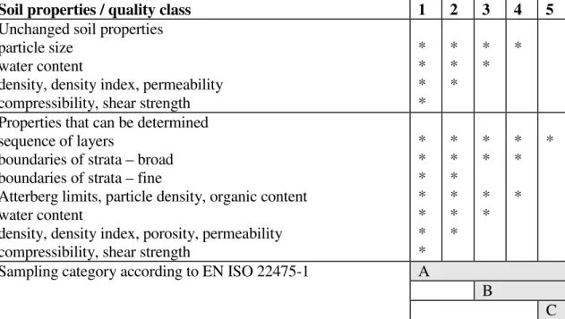
NOTE For laboratory testing purposes, soil samples are classified in five quality classes (see 3.4.1).
1.5.3.6
remoulded sample
sample of which the soil or rock structure is fully disturbed
1.5.3.7
remoulded specimen
fully disturbed specimen, at natural water content
1.5.3.8
re-compacted specimen
specimen forced into a mould with a rammer or under desired static stress state
1.5.3.9
reconstituted specimen
specimen prepared in the laboratory; for fine soils, it is prepared as a slurry (at or above the liquid limit) and then consolidated (sedimented); for coarse soils, it is either poured or pluviated in dry (dried) or wet conditions and compacted, or consolidated
1.5.3.10
re-consolidated specimen
specimen compressed in a mould or cell under static pressure while allowing drainage to take place
1.5.3.11 sample
portion of soil or rock recovered from the ground by sampling techniques
1.5.3.12 specimen
part of a soil or rock sample used for a laboratory test
1.5.3.13
strength index test
test of a nature that yields an indication of the shear strength, without necessarily giving a representative value
NOTE The results of such a test are subject to uncertainty.
1.5.3.14 swelling
expansion due to reduction of effective stress resulting from either reduction of total stress or absorption of (in general) water at constant total stress
NOTE Swelling includes the reverse of both compression and consolidation.
1.5.3.15
undisturbed sample
sample where no change in the soil characteristics of practical significance has occurred
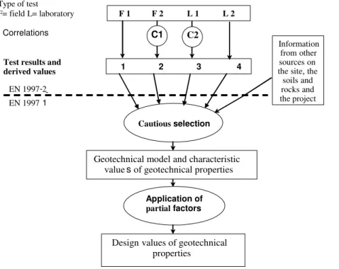
1.6 Test results and
derived values
(1) Test results and derived values form the basis for the selection of characteristic values of ground properties to be used for the design of geotechnical structures, in accordance with 2.4.3 of EN 1997-1:2004.
NOTE 1 The process of geotechnical design consists of a few successive phases (see Figure 1.1), the first of which covers the site investigation and testing, whereas the next one is devoted to the determination of characteristic values, and the last phase covers the design verification calculations. Rules for the first phase are given in the
present standard. The determination of characteristic values and the design of the structures are covered by EN 1997-1.
Figure 1.1 — General framework for the selection of derived values of geotechnical properties
(2) Test results can be experimental curves or values of geotechnical parameters. In Annex A, a list of test results is given to serve as a reference to test standards6.
(3) Derived values of geotechnical parameters and/or coefficients, are obtained from test results by theory, correlation or empiricism.
NOTE 2 The examplesof correlations used to determine derived values givenin the annexes to Section 4 of this standard are obtained from the literature. These correlations may correlate the value of a geotechnical parameter or coefficient with a test result, such as the qc-value of a CPT. They may also connect a geotechnical parameter to a test
result by means of theoretical considerations (for example, when deriving a value of the angle of shearing resistance
ϕ’ from pressuremeter test results or from the index of plasticity).
NOTE 3 In certain cases, the derivation of geotechnical parameters by means of a correlation is not made before the determination of the characteristic value, butafter the test results have been corrected or transformed into conservative estimates.
1.7 The link between EN 1997-1 and EN 1997-2
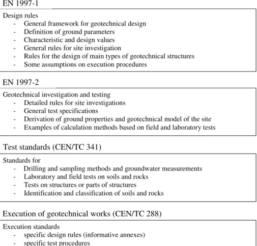
(1) Figure 1.2 presents the general architecture of the CEN standards related to geotechnical
engineering problems and those directly linked to EN 1997. The design part is covered by EN 1997-1. The present standard gives rules for ground investigations and obtaining geotechnical parameters or coefficients values to be used for determining the characteristic values (as specified in EN 1997-1). It gives also informative examples of calculation methods for spread and deep foundations. The implementation of EN 1997 needs information based on other standards, in particular those related to ground investigations and to the execution of geotechnical works.
6 Geotechnical test standards, yielding these results are prepared by CEN/TC341. Type of test
F= field L= laboratory
Correlations
Test results and
derived values 1 2 3 4
F 1 F 2 L 1 L 2
C1 C2
Cautious selection
Geotechnical model and characteristic values of geotechnical properties
Designvalues of geotechnical properties Application of partial factors Information fromother sourceson thesite, the
soilsand rocksand the project EN 1997 -1 EN 1997-2
Geotechnical investigation and testing - Detailed rules for site investigations - General test specifications
- Derivation of ground properties and geotechnical model of the site - Examples of calculation methods based on field and laboratory tests
EN 1997-2
Execution standards
- specific design rules (informative annexes) - specific test procedures
Execution of geotechnical works (CEN/TC 288)
Standards for
- Drilling and sampling methods and groundwater measurements - Laboratory and field tests on soils and rocks
- Tests on structures or parts of structures - Identification and classification of soils and rocks
Test standards (CEN/TC 341)
Design rules
- General framework for geotechnical design - Definition of ground parameters
- Characteristic and design values - General rules for site investigation
- Rules for the design of main types of geotechnical structures - Some assumptions on execution procedures
EN 1997-1
Figure 1.2 — General architecture of the CEN standards linked with EN 1997
1.8 Symbols and units
(1) For the purpose of EN 1997-2 the following symbols apply.
NOTE The notation of the symbols used is based on ISO 3898:1997.
Latin letters
Cc compression index
c' cohesion intercept in terms of effective stress cfv undrained shear strength from the field vane test cu undrained shear strength
Cs swelling index
cv coefficient of consolidation
Cα coefficient of secondary compression
Dn particle size such that n % of the particles by weight are smaller than that size e.g. D10, D15, D30, D60 and D85
E Young’s modulus of elasticity
E ' drained (long term) Young’s modulus of elasticity EFDT flexible dilatometer modulus
EM Ménard pressuremeter modulus
Emeas measured energy during calibration Eoed oedometer modulus
EPLT modulus from plate loading test Er energy ratio (= Emeas / Etheor ) Etheor theoretical energy
Eu undrained Young's modulus of elasticity E0 initial Young's modulus of elasticity
E50 Young's modulus of elasticity corresponding to 50 % of the maximum shear strength IA activity index
IC consistency index ID density index
IDMT material index from the flat dilatometer test
KDMT horizontal stress index from the flat dilatometer test IL liquidity index
IP plasticity index
ks coefficient of sub-grade reaction mv coefficient of compressibility
N number of blows per 300 mm penetration from the SPT
Nk cone factor for CPT, (see equation (4.1)) Nkt cone factor for CPTU, (see equation (4.2))
N10L number of blows per 10 cm penetration from the DPL
N10M number of blows per 10 cm penetration from the DPM
N10H number of blows per 10 cm penetration from the DPH
N10SA number of blows per 10 cm penetration from the DPSH-A N10SB number of blows per 10 cm penetration from the DPSH-B N20SA number of blows per 20 cm penetration from the DPSH-A N20SB number of blows per 20 cm penetration from the DPSH-B N60 number of blows from the SPT corrected to energy losses
(N1)60 number of blows from the SPT corrected to energy losses and normalized for effective
vertical overburden stress
pLM Ménard limit pressure qc cone penetration resistance
qt cone penetration resistance corrected for pore water pressure effects qu unconfined compressive strength
wopt optimum water content
Greek letters
α correlation factor for EOED and qc, (see Equation (4.3)) ϕ angle of shearing resistance
ϕ' angle of shearing resistance in terms of effective stress µ correction factor to derive cu from cfv, (see Equation (4.4)) ρd;max maximum dry density
σC unconfined compression strength of rock
σ'p effective pre-consolidation pressure σT tensile strength of rock
σv0 total vertical stress σ'v0 effective vertical stress
ν Poisson’s ratio
Abbreviations
CPT cone penetration test
CPTU cone penetration test with pore water pressure measurement
DMT flat dilatometer test
DP dynamic probing
DPL dynamic probing light
DPM dynamic probing medium
DPH dynamic probing heavy
DPSH-A dynamic probing superheavy, type A DPSH-B dynamic probing superheavy, type B
FDP full displacement pressuremeter
FDT flexible dilatometer test
FVT field vane test
MPM Ménard pressuremeter
PBP pre-bored pressuremeter
PLT plate loading test
PMT pressuremeter test
RDT rock dilatometer test
SBP self-boring pressuremeter
SDT soil dilatometer test
SPT standard penetration test
WST weight sounding test
(2) For geotechnical calculations, the following units or their multiples are recommended:
− force kN
− moment kNm
− mass density kg/m3
− weight density kN/m3
− stress, pressure, strength and stiffness kPa
− coefficient of permeability m/s
− coefficient of consolidation m2/s
Section 2
Planning of ground investigations
2.1 Objectives
2.1.1 General
(1)P Geotechnical investigations shall be planned in such a way as to ensure that relevant
geotechnical information and data are available at the various stages of the project. Geotechnical information shall be adequate to manage identified and anticipated project risks. For intermediate and final building stages, information and data shall be provided to cover risks of accidents, delays and damage.
(2) The aims of a geotechnical investigation are to establish the soil, rock and groundwater conditions, to determine the properties of the soil and rock, and to gather additional relevant knowledge about the site.
(3)P Careful collection, recording and interpretation of geotechnical information shall be made. This information shall include ground conditions, geology, geomorphology, seismicity and hydrology, as relevant. Indications of the variability of the ground shall be taken into account. (4) Ground conditions which may influence the choice of geotechnical category should be determined as early as possible in the investigation.
NOTE As a result of the geotechnical investigations, it may be necessary to change the geotechnical category of the project (see 1.1.2 (4)).
(5) Geotechnical investigations should consist of ground investigations, and other investigations for the site, such as:
− the appraisal of existing constructions, e.g. buildings, bridges, tunnels, embankments and slopes;
− the history of development on and around the site.
(6) Before designing the investigation programme, the available information and documents should be evaluated in a desk study.
(7) Examples of information and documents that can be used are:
− topographical maps;
− old city maps describing the previous use of the site; − geological maps and descriptions;
− engineering geological maps;
− hydrogeological maps and descriptions;
− geotechnical maps;
− aerial photos and previous photo interpretations; − aero-geophysical investigations;
− previous investigations at the site and in the surroundings; − previous experiences from the area;
− local climatic conditions.
(8) Ground investigations should consist of field investigations, laboratory testing, additional desk studies and controlling and monitoring, where appropriate.
(9)P Before the investigation programme has been drawn up the site shall be visually examined and the findings recorded and cross-checked against the information gathered by desk studies. (10) The ground investigation programme should be reviewed as the results become available so that the initial assumptions can be checked. In particular:
− the number of investigation points should be extended if it is deemed necessary to obtain an accurate insight into the complexity and the variability of the ground at the site;
− the parameters obtained should be checked to see that they fit into a consistent behavioural pattern for soil or rock. If necessary additional testing should be specified;
− any limitations in the data, revealed according to EN 1997-1:2004, 3.4.3 (1) should be considered.
(11) Special attention should be paid to sites that have been previously used, where disturbance of the natural ground conditions may have taken place.
(12)P An appropriate quality assurance system shall be in place in the laboratory, in the field and in theengineering office, and quality control shall be exercised competently in all phases of the investigations and their evaluation.
2.1.2 Ground
(1)P Ground investigations shall provide a description of ground conditions relevant to the proposed works and establish a basis for the assessment of the geotechnical parameters relevant for all construction stages.
(2) The information obtained should enable assessment of the following aspects, if possible: − the suitability of the site with respect to the proposed construction and the level of acceptable
risks;
− the deformation of the ground caused by the structure or resulting from construction works, its spatial distribution and behaviour over time;
− the safety with respect to limit states (e.g. subsidence, ground heave, uplift, slippage of soil and rock masses, buckling of piles, etc.);
− the loads transmitted to the structure from the ground (e.g. lateral pressures on piles) and the extent to which they depend on its design and construction;
− the foundation methods (e.g. ground improvement, whether it's possible to excavate, driveability of piles, drainage);
− the sequence of foundation works;
− the effects of the structure and its use on the surroundings;
− any additional structural measures required (e.g. support of excavation, anchorage, sleeving of bored piles, removal of obstructions);
− the effects of construction work on the surroundings;
− the type and extent of ground contamination on, and in the vicinity of, the site; − the effectiveness of measures taken to contain or remedy contamination.
2.1.3 Construction materials
(1)P Geotechnical investigations of soil and rock for use as construction materials shall provide a description of the materials to be used and shall establish their relevant parameters.
(2) The information obtained should enable an assessment of the following aspects: − the suitability for the intended use;
− the extent of deposits;
− whether it is possible to extract and process the materials, and whether and how unsuitable material can be separated and disposed of;
− the prospective methods to improve soil and rock;
− the workability of soil and rock during construction and possible changes in their properties during transport, placement and further treatment;
− the effects of construction traffic and heavy loads on the ground;
− the prospective methods of dewatering and/orexcavation, effects of precipitation, resistance to weathering, and susceptibility to shrinkage, swelling and disintegration.
2.1.4 Groundwater
(1)P Groundwater investigations shall provide all relevant information on groundwater needed for geotechnical design and construction.
(2) Groundwater investigations should provide, when appropriate, information on:
− the depth, thickness, extent and permeability of water-bearing strata in the ground, and joint systems in the rock;
− the elevation of the groundwater surface or piezometric surface of aquifers and their variation over time and actual groundwater levels including possible extreme levels and their periods of recurrence;
− the pore water pressure distribution;
− the chemical composition and temperature of groundwater.
(3) The information obtained should be sufficient to assess the following aspects, where relevant: − the scope for and nature of groundwater-lowering work;
− possible harmful effects of the groundwater on excavations or on slopes (e.g. risk of hydraulic failure, excessive seepage pressure or erosion);
− any measures necessary to protect the structure (e.g. waterproofing, drainage and measures against aggressive water);
− the effects of groundwater lowering, desiccation, impounding etc. on the surroundings; − the capacity of the ground to absorb water injected during construction work;
− whether it is possible to use local groundwater, given its chemical constitution, for construction purposes.
2.2 Sequence of ground investigations
(1)P The composition and the extent of the ground investigations shall be based on the
anticipated type and design of the construction, e.g. type of foundation, improvement method or retaining structure, location and depth of the construction;
(2)P The results of the desk studies and the site inspection shall be considered when selecting the investigation methods and locating the various investigation points. Investigations shall be targeted at points representing the variation in ground conditions for soil, rock and groundwater. (3) Ground investigations should normally be performed in phases depending on the questions raised during planning, design and construction of the actual project. The following phases are treated separately in Section 2:
− preliminary investigations for positioning and preliminary design of the structure (see 2.3); − design investigations (see 2.4);
− controlling and monitoring (see 2.5).
NOTE The provisions in this document are based on the premise that the results from investigations recommended in one phase are available before the next phase is started.
(4) In cases where all investigations are performed at the same time, 2.3 and 2.4 should be considered simultaneously.
NOTE The different stages of ground investigations, including laboratory and field work and the process of evaluating soil and rock parameters, can follow the schemes in B.1 and B.2.
2.3 Preliminary investigations
(1) The preliminary investigations should be planned in such a way that adequate data are obtained, if relevant, to:
− assess the overall stability and general suitability of the site;
− assess the suitability of the site in comparison with alternative sites; − assess the suitable positioning of the structure;
− evaluate the possible effects of the proposed works on surroundings, such as neighbouring buildings, structures and sites;
− identify borrow areas;
− consider the possible foundation methods and any ground improvements;
− plan the design and control investigations, including identification of the extent of ground which may have significant influence on the behaviour of the structure.
(2)A preliminary ground investigation should supply estimates of soil data concerning, if relevant:
− the type of soil or rock and their stratification; − the groundwater table or pore pressure profile;
− the preliminary strength and deformation properties for soil and rock;
− the potential occurrence of contaminated ground or groundwater that might be hazardous to the durability of construction material.
2.4 Design investigations
2.4.1 Field investigations 2.4.1.1 General
(1)P In cases where the preliminary investigations do not provide the necessary information to assess the aspects mentioned in 2.3, complementary investigations shall be performed during the design investigation phase.
(2) If relevant, field investigations in the design phase should comprise:
− drilling and/or excavations (test pits including shafts and headings) for sampling;
− groundwater measurements;
− field tests.
(3) Examples of the various types of field investigations are:
− field testing (e.g. CPT, SPT, dynamic probing, WST, pressuremeter tests, dilatometer tests, plate load tests, field vane tests and permeability tests);
− soil and rock sampling for description of the soil or rock and laboratory tests;
− groundwater measurements to determine the groundwater table or the pore pressure profile and their fluctuations;
− geophysical investigations (e.g. seismic profiling, ground penetrating radar, resistivity measurements and down hole logging);
− large scale tests, for example to determine the bearing capacity or the behaviour directly on prototype elements, such as anchors.
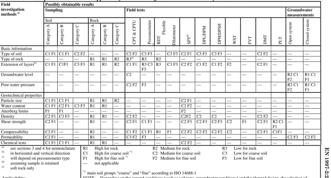
(4) To develop strategies for planning field investigations, Table 2.1 can be used as a guide to the applicability of the field investigations covered in Sections 3 and 4.
NOTE See also B.2.
(5)P Where ground contamination or soil gas is expected, information shall be gathered from the relevant sources. This information shall be taken into account when planning the ground
investigation.
Table 2.1 — Simplified overview of the applicability of field investigation methodsa) covered by Sections 3 and 4
Possibly obtainable results
Sampling Field tests Groundwater
measurements Soil Rock Field investigation methods a) C at eg or y A Cat eg or y B C at eg or y C C at eg or y A C at eg or y B C at eg or y C C PT & C PT U P re ss ur em et er c) R DT F le xi bl e Di la to m et er S PT d) DP L /DP M DP H/ DP SH W ST F VT DM T P L T Op en s ys te m Clo se d sy st em Basic information Type of soil C1 F1 C1 F1 C2 F2 — — — C2 F2 C3 F3 — C3 F3 C2 F1 C3 F3 C3 F3 — — C2 F2 — — — Type of rock — — — R1 R1 R2 R3e) R3 R2 — — — — — — — — — Extension of layersb) C1 F1 C1F1 C3 F3 R1 R1 R2 C1 F1 R3 C3 F3 R3 C3 F3 C2 F2 C1 F2 C1 F2 F2 — C2 F1 — — — Groundwater level — — — — — — C2 — — — — — — — — — — R2 C1 F2 R1 C1 F1 Pore water pressure — — — — — — C2 F2 F3 — — — — — — — — — R2 C1
F2 R1 C1 F1 Geotechnical properties Particle size C1 F1 C1 F1 R1 R1 R2 — — — — C2 F1 — — — — — — — — Water content C1 F1 C2 F1 C3 F3 R1 R1 — — — — — C2 F2 — — — — — — — — Atterberg limits F1 F1 — — — — — — — — F2 — — — — — — — — Density C2 F1 C3 F3 — R1 R1 — C2 F2 — — — C2F2 C2 C2 — — C2 F2 — — — Shear strength C2 F1 — — R1 — — C2 F1 C1 F1 — — C2 F3 C2 F3 C2 F3 C2 F1 C2 F1 R2 C1 F1 — — Compressibility C2 F1 — — R1 — — C1 F2 C1 F1 R1 F1 C2 F2 C2 F2 C2 F2 C2 — C2 F1 C1F1 — — Permeability C2 F1 — — R1 — — C3 F2 F3 — — — — — — — — — C2 F3 C2 F2 Chemical tests C1 F1 C1 F1 — R1 R1 — — — — — C2 F2 — — — — — — — —
a) see sections 3 and 4 for nomenclature b) in horizontal and vertical direction c) will depend on pressuremeter type d) assuming sample is retained e) soft rock only
Applicability:
R1 High for rock R2 Medium for rock R3 Low for rock C1 High for coarse soil *) C2 Medium for coarse soil C3 Low for coarse soil
F1 High for fine soil *) F2 Medium for fine soil F3 Low for fine soil
— not applicable
*) main soil groups “coarse” and “fine” according to ISO 14688-1
NOTE Depending on the ground conditions (such as soil type, groundwater conditions) and the planned design, the selection of investigation methods will vary and may deviate from this table.
25
(6)P If ground contamination or soil gas is detected in the course of ground investigations, this shall be reported to the client and the responsible authorities.
2.4.1.2 Field investigation programme
(1)P The field investigation programme shall contain:
− a plan with the locations of the investigation points including the types of investigation; − the depth of the investigations;
− the types of sample (category, etc.) to be taken including specifications for the number and depth at which they are to be taken;
− specifications on the groundwater measurement; − the types of equipment to be used;
− the standards to be applied.
2.4.1.3 Locations and depths of the investigation points
(1)P The locations of investigation points and the depths of the investigations shall be selected on the basis of the preliminary investigations as a function of the geological conditions, the dimensions of the structure and the engineering problems involved.
(2) When selecting the locations of investigation points, the following should be observed: − the investigation points should be arranged in such a pattern that the stratification can be
assessed across the site;
− the investigation points for a building or structure should be placed at critical points relative to the shape, structural behaviour and expected load distribution (e.g. at the corners of the foundation area);
− for linear structures, investigation points should be arranged at adequate offsets to the centre line, depending on the overall width of the structure, such as an embankment footprint or a cutting;
− for structures on or near slopes and steps in the terrain (including excavations), investigation points shouldalso be arranged outside the project area, these being located so that the stability of the slope or cut can be assessed. Where anchorages are installed, due consideration should be given to the likely stresses in their load transfer zone;
− the investigation points should be arranged so that they do not present a hazard to the
structure, the construction work, or the surroundings (e.g. as a result of the changes they may cause to the ground and groundwater conditions);
− the area considered in the design investigations should extend into the neighbouring area to a distance where no harmful influence on the neighbouring area is expected.
− for groundwater measuring points, the possibility of using the equipment installed during the ground investigation for continued monitoring during and after the construction period should be considered.
(3) Where ground conditions are relatively uniform or the ground is known to have sufficient strength and stiffness properties, wider spacing or fewer investigation points may be applied. In either case, this choice should be justified by local experience.
(4)P In cases where more than one type of investigation is planned at a certain location (e.g. CPT and piston sampling), the investigation points shall be separated by an appropriate distance.
26
(5) In thecase of a combination of, for example, CPTs and boreholes, the CPTs should be carried out prior to the boreholes. The minimum spacing should then be such that the borehole does not or is considered unlikely to encounterthe CPT hole. If the drilling is conducted first, the CPT should be carried out at a horizontalseparationof at least 2 m.
(6)P The depth of investigations shall be extended to all strata that will affect the project or are affected by the construction. For dams, weirs and excavations below groundwater level, and
where dewatering work is involved, the depth of investigation shall also be selected as a function of the hydrogeological conditions. Slopes and steps in the terrain shall be explored to depths below any potential slip surface.
NOTE For the spacing of investigation points and investigation depths, the values given in B.3 can be used as guidance.
2.4.1.4 Sampling
(1)P The sampling categories (see 3.4.1 and 3.5.1), and the number of samples to be taken shall be based on:
− the aim of the ground investigation; − the geology of the site;
− the complexity of the geotechnical structure.
(2)P Foridentification and classification of the ground, at least one borehole or trial pit with sampling shall be available. Samples shall be obtained from every separate ground layer influencing the behaviour of the structure.
(3) Sampling may be replaced by field tests if there is enough local experience to correlate the field tests with the ground conditions to ensure unambiguous interpretation of the results. (4) Further details on sampling are given in Section 3.
2.4.1.5 Groundwater
(1)P Groundwater measurements shall be planned and carried out in accordance with 3.6.
2.4.2 Laboratory tests 2.4.2.1 General
(1) Prior to setting up a test programme, the expected stratigraphy at the site should be
established and the strata relevant for design selected to enable the specification of the type and number of tests in each stratum. Stratum identification should be a function of the geotechnical problem, its complexity, the local geology and the required parameters for design.
2.4.2.2 Visual inspection and preliminary groundprofile
(1) Samples and trial pits should be inspected visually and compared with field logs of the drillings so that the preliminary ground profile can be established. For soil samples, the visual inspection should be supported by simple manual tests to identify the soil and to give a first impression of its consistency and mechanical behaviour.
(2) If distinct and significant differences in the properties between different portions of one stratum are found, the preliminary soil profile should be further subdivided.
(3) Where practicable, the quality of the sample should be assessed before laboratory tests are performed. Quality classes for soil samples are defined in Table 3.1.
2.4.2.3 Test programme
(1)P The type of construction, the type of ground and stratigraphy and the geotechnical parameters needed for design calculations shall be taken into account when setting up the laboratory test programme.
(2) The laboratory test programme depends in part on whether comparable experience exists. The extent and quality of comparable experience for the specific soil or rock should be established. The results of field observations on neighbouring structures, when available, should also be used. (3)P The tests shall be run on specimens representative of the relevant strata. Classification tests shall be used to check whether the samples and test specimens are representative.
NOTE This can be checked in an iterative way. In a first step, classification tests and strength index tests are performed on as many samples as possible to determine the variability of the index properties of a stratum. In a second step, an assessment of how representative the samples used for the strength and compressibility tests are of the stratum can be checked by comparing the results of the classification and strength index tests for the samples with all results from the classification and strength index tests for the stratum.
(4) The need for more advanced testing or additional site investigation as a function of the geotechnical aspects of the project, soil type, soil variability and computation model should be considered.
2.4.2.4 Number of tests
(1)P The necessary number of specimens to be tested shall be established depending on the homogeneity of the ground, the quality and amount of comparable experience with the ground and the geotechnical category of the problem.
(2) To allow for difficult soil, damaged specimens and other factors, additional test specimens should be made available, whenever possible.
(3) Depending on the test type, a minimum number of specimens should be investigated.
NOTE A recommended minimum number for some test types can be taken from the tables in Annexes L to W (except Annexes O and T). The annexes can also be used to check whether the extent of the testing was sufficient.
(4) The minimum number of tests may be reduced if the geotechnical design does not need to be optimised and uses conservative values of the soil parameters, or if comparable experience or combination with field information applies.
2.4.2.5 Classification tests
(1) Soil and rock classification tests should be performed to determine the composition and index properties of each stratum. The samples for the classification tests should be selected in such a way that the tests are approximately equally distributed over the complete area and the full depth of the strata relevant for design. Thus the results should give the range of index properties of the relevant layers.
(2) The results of the classification tests should be used to check if the extent of the investigations was sufficient or if a second investigation stage is needed.
(3) Suitable routine classification tests for ground samples with various degrees of disturbance are presented in Table 2.2. The routine tests are generally performed in all phases of the ground investigation (see 2.2 (3)).
2.4.2.6 Tests on samples
(1)P Samples for testing shall be selected so as to cover the range of index properties of each relevant stratum.
(2) For a fill or a stratum of sand or gravel, reconstituted specimens may be tested. Reconstituted specimens should have approximately the same composition, density and water content as in-situ material.
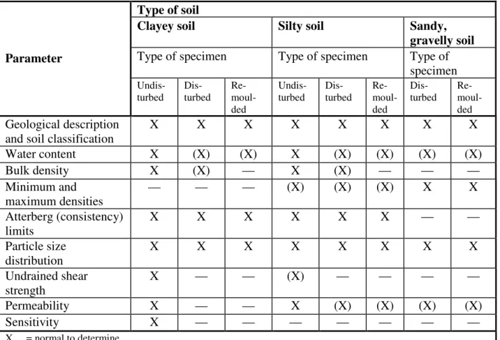
Table 2.2 — Soil classification tests Type of soil
Clayey soil Silty soil Sandy,
gravelly soil
Type of specimen Type of specimen Type of
specimen
Parameter
Undis-turbed Dis-turbed Re- moul-ded
Undis-turbed Dis- turbed Re- moul-ded
Dis-turbed Re- moul-ded
Geological description and soil classification
X X X X X X X X Water content X (X) (X) X (X) (X) (X) (X) Bulk density X (X) — X (X) — — — Minimum and maximum densities — — — (X) (X) (X) X X Atterberg (consistency) limits X X X X X X — — Particle size distribution X X X X X X X X Undrained shear strength X — — (X) — — — — Permeability X — — X (X) (X) (X) (X) Sensitivity X — — — — — — — X = normal to determine
(X) = possible to determine, not necessarily representative — = not applicable
NOTE For some types of soil,further tests may be considered, for example the determination of organic content, particle density and activity.
(3) Laboratory tests to determine parameters for geotechnical calculations are given in Table 2.3. (4) Suitable routine laboratory tests for rock samples giving the necessary basis for the
description of the rock material are as follows: − the geological classification;
− the density or bulk mass density (ρ) determination; − the water content (w) determination;
− the porosity (n) determination;
− the uniaxial compression strength (σC) determination;
− the Young’s modulus of elasticity (E) and Poisson’s ratio (ν) determination; − the point load strength index test (Is,50).
(5) The classification of rock core samples will normally comprise a geological description, the core recovery, the Rock Quality Designation (RQD), the degrees of induration, fracture log, weathering and fissuring. In addition to the routine te