1
Application of Pavement Condition Index (PCI) Methodology
in Pavement Distress Evaluation and Maintenance Prioritization
Kamal Masoud Mergi1 and Awad El Karim Mustafa Mohamed2
1National Roads & Bridges Corporation, Khartoum, Sudan 2Building and Road Research Institute, University of Khartoum, Sudan
Abstract: The study is concerned with the adaptation of visual condition survey methodology and implementation of Pavement Condition Index (PCI) in evaluation of pavement distress and prioritization of pavement maintenance of the Sudan paved road network. It is implemented on large part of the national road network (55% of the road network). The Sudan national highway has no enough budgets available for maintenance, and there is no standard priority method used to allocate the available pavement maintenance budget. The study aims to adapt assessment methodology and contribute in making better decisions with respect to expenditures of pavement maintenance in Sudan. In this research a comprehensive road visual condition survey for pavement distresses of the 60% of road network length (2780 km) is carried out and the study ranks the project according to its Index (PCI, excellent, very good, good, fair, bad, failed) and set initial priorities based on “the worst first” concept. The survey quantifies types, severity, density and percent of each distress on each road and determines its condition index, finally, a list of priorities and maintenance needs were generated. The study uses generated Polynomial equations instead of standard curves. The correlation between the data obtained from the standard curves and polynomials shows best fit condition (R2 more than 0.99).This paper presents the methodology and discusses the results of the visual condition survey.The visual condition survey methodology adopted to determine the pavement condition for Sudan paved road Network, based on ASTM Standard D6433, 2003. It provides a common method for describing distress on asphalt pavement in Sudan road network like cracks, bleeding, bump and sags, potholes, patching, raveling, swelling, etc…. It improves communication within pavement community, by fostering more uniform and consistent definitions of pavement distress. It increases the awareness of importance of road maintenance and rehabilitation and provides a tool for formulating rational bases for assessment of pavement condition and evaluation. Thus sets initial priorities for adopting roads project short list for rehabilitation in certain year. It can, therefore, play an important role in developing the strategic
2
planning of road maintenance, and when detailed surveys were conducted, the inventory data can be used at project level.The outcomes of this study are development of road numbering system; adaptation of pavement condition survey methodology; evaluation of (2782 km) pavement condition on the national roads and prioritizing the maintenance of road sections using PCI and worst first concept.
Keywords: Evaluation, Road Pavement, Identification System, Road Distress, Prioritization, Maintenance. لا صلختسم : عوضومب ثحبلا اذه َىِنُع / كًبُطو ،اهنٌب ةلضافملاو قرطلا فصر ةناٌص تاراٌخ تاٌمبسأ وأ تاٌولوأ نادوسلاب ةٌموملا قرطلا ةكبش نم ردمم ءزج ىلع ( 55 % ماعلا ًف قرطلا ةكبش نم 2005 م ) اهل رفوتت لا ًتلاو ، مادختساب ةدعالرٌوطت ىلإ صلخ ثٌح ةٌلوا تاناٌب ةدعال رٌوطت لاجمل قرطتو ،ةناٌصلا لامعلأ ةٌفاكلا ةٌنازٌملا ًف ةمهاسملل نلذو ،ةساردلا اهتلمش ًتلا نادوسلاب ةتلفسملا ةٌموملا قرطلاب فصرلا ةلاح لٌلحتل لسكإ جمانرب لٌهأتلاو ةناٌصلا تارامثتسا ىلع ةظفاحملاو قرطلا هذهل ةناٌصلا تارارل نٌسحت . ةمٌرط رٌوطت ثحبلا هذه ًف مت اهبوٌع ةجرد تددح ثٌح ةتلفسملا قرطلا بوٌعل لماش حسم ىلع لمتشاو ،ةٌموملا قرطلا مٌلرتو ةٌمستل ىلعو ًئاشنلإاو ًسدنهلا مٌمصتلا تامولعمل رصح ىلع لمتشا امك ،كٌرط لكب اهتفاثكو اهتدش ةبسنو اهتحاسمو ةدمل لماش يرورم رصح 24 ةعاس . بوساحلا جمانرب دوز مث نمو لامعلأا دونبل ةفلكتلا تامولعم عمج مت امك HDM-4 ًتلفسلأا فصرلا ةناٌص تاٌولولأ لوادجو ةٌنازٌملا لوادج ىلع ل ِصُحو اهلٌلحت دعب تامولعملا نلتب ةساردلا اهتلمش ًتلا قرطلل . ىلاوح يرصبلا حسملا ةسارد تلمش دملو ( 2780 ) ةتلفسملا قرطلا نم رتمولٌك ةلمج نم نادوسلاب 5000 أوسلأا أدبم ىلع ًاءانب ًئدبم تاٌولوا لودج ًف اهتلاح بسح قرطلا تبترو ،رتمولٌك ( راهنملا ) ًكٌمانٌدلا طورخملا تارابتخا نم ددعل ءارجا ىلع توتحا امك ،ًلاوأ DCP نم ةراتخم حسم تادحو ىلع ًناطٌربلا لمنلا ثوحب ربتخم نم رداص بوساح جمانرب مادختساب جئاتنلا تللحو ،قرطلا نلت TRL ًاٌئاصحا تللحو فصرلل ًئاشنلإا لماعملا جئاتن SNP فصرلا ةلاح لٌلد جئاتن عم PCI امهنٌب طابترلإا ةجرد تددحو ةدحولا سفنل . يرصبلا حسملا جئاتن لٌلحتل تاٌجمرب رٌوطت ًف ًلابمتسم مدختست نأ لجا نم تاجردلا ةددعتم تلاداعم رٌوطت متو فصرلا ةلاح لٌلد ةمٌرط عم ةمفرملا ةٌساٌملا تاٌنحنملا نع ًلادب PCI ةجرد نأ ةٌضاٌرلا تلاٌلحتلا تحضوأو ةرٌبك تناك طابترلإا ( 0,99 ) نٌتمٌرطلا مادختساب لٌلحتلا جئاتن تمباطتو . ىلاوح نأ ثحبلا صلخ دملو ( 17.4 )% نأو ،ةلجاع ةناٌصل جاتحٌو ةئٌدر ةلاح ًف ناك ةساردلا تلو هفوصرملا قرطلا نم ( 20.6 % ) قرطلا فصر نم نأو ،ةلوبمم ةلاح ًف ( 22.9 % ) نأو ةدٌج ةلاح ًف ( 39.1 % ) رشؤم طسوتم نأو ،ةزاتمم ىلإ ًادج ةدٌج ةلاح ًف ناك قرطلا فصر ةلاح ( 57 % ) ةلاحلا ًف يأ " لوبمم " ىلع ظافحلا لجأ نم رثكأ دوهج لذب بجوتسٌ امم ، أوسلأا ىلإ اهتلاح روهدتتس لاإو ،قرطلا . عاوناو اهل ةجاحلا ىدمو ةناٌصلا ةرادإ تاناٌب ملعل ثحبلا قرطتو مدختسملا ًلودلا ننبلا جمانرب نع هذبن ضرعو تاٌمبسلأا عضو تاٌنمتو ؤبنتلا جذامنل قرطتو ةبولطملا تاناٌصلا لٌلحتلا ًف . فصرلا ةناٌص ةاردا ًف ةمدختسملا تاناٌبلا ةٌافكو ةٌلوثوملا ةجرد ةٌمهأ ىلع ثحبلا نًمأ ثٌح
3 ًتلا تاٌوتسملا دٌدحتو فصرلا ةناٌص تاٌجٌتارتسا ىلع لوصحلل ةبولطملا تاناٌبلا نلت عاونأو تاٌوتسم ددحو فصرلا ةلاح رٌٌغتل ةددحملا تاناٌصلا لامعا ءارجاب اهدنع لخدتلا بجٌ ءارجاو اهمٌبطت ةٌفٌكو تاناٌصلا عاوناو بوساحلا جمانرب ةطساوب لٌلحتلا HDM-4 ًلودلا ننبلا لبل نم رداصلا . نكمٌ هنا ىلإ ًاضٌأ ثحبلا صلخو جمانرب مادختسا HDM-4 ًف همادختسا نكمٌ جمانربلا نأب ىصوو فصرلا ةناٌص تاٌجتارتسا رٌوطتل حاجنب فصرلا ةلاح ساٌمل ةٌكٌتاموتولأا ةزهجلاا نم تاناٌب مادختساب جمانربلا ةرٌاعم تمت اذإ ةناٌصلا تاعورشم لٌلحت فصرلا حطس ساٌل ةدعم لثم ةٌئاشنلإا هتولو RST فصرلا تامبط فارحنا ساٌل ةدعمو FWD . 1. Introduction
The total road network in the Sudan is estimated to be (30000) kilometers, (43%) (13000 kilometers) of them are considered to be as urgent needs, while the total paved kilometers up to end of 2006 is about (5000) km, most located in the northern and central parts of the country, (50%) of these roads were constructed during 1989 – 2005, and the remaining was constructed approximately during 1967-1989.
The Sudan paved road network is sub-divided into links which are uniform with respect to traffic, environment, geometry, and pavement type and construction history. The links were subdivided into sections which are uniform in respect of pavement condition then the sections were subdivided into sample units each of which of (5000m) length. For the purpose of this analysis the sample units were selected randomly in such way that not less than (60%) of each road section should be surveyed, and all type and severity of pavement distress were assessed by visual inspection for each sample unit and road section.
The distress data are used to calculate the PCI for each sample unit. The PCI of the pavement section is determined based on the PCI of the inspected sample units within the section.
The PCI is a numerical indicator that rates the surface condition of the pavement is adopted to measure the present condition of the pavement based on the distress observed on the surface of the surveyed sample units.
This procedure cannot measure directly the structural capacity nor does it provide direct measurement of skid resistance or roughness. It provides an objective and rational basis for determining maintenance and repair needs and priorities. Continuous monitoring of the PCI is used to establish the rate of pavement deterioration, which permits early identification of major rehabilitation needs. The PCI provides feedback on pavement performance for validation or improvement of current pavement design and maintenance procedures.
4 2. Road Identification Systems
Road identification numbering system is considered one of the essential parts in the road management systems and related information systems, in order to link each road section with their information files containing geometric properties, history, traffic pavement and non-pavement elements, pavement condition and other necessary information used for road maintenance and rehabilitation or improvement programming or prediction of road pavement condition in the future and generating of maintenance and rehabilitation strategies using software.
2.1 Methodology of Road’s Identification
The existing roads network and tracks used by the vehicles and trans-Africa roads linking the Sudan with border countries in transverse and longitudinal direction were identified, then the road network is grouped in to two groups:
- East- West routes, perpendicular to River Nile with a major route starting from east of Kasala city at Eastern Sudan- Eritrea country border passed Khartoum city and ends at the Western of the Sudan – Chad country border.
- North – South routes, parallel to River Nile with a major route starting from Wadi Halfa city at Northern of Sudan- Egypt country border passed Khartoum city and ends at Nomoli town at the southern of Sudan – Uganda country border.
The number of routes in each direction are (17) routes, each of which composed of many road links subdivided to road sections subdivided to many sample units.
The road link is a branch or a major road which has same history, construction year, and year of opening which linked between two major cities, while the section is a subdivision from it which have similar traffic counts or maintenance history linking towns and small cities along the alignment. The sample unit is a subdivision of sections of certain length, which should be decided by maintenance and planning directorate for the purpose of visual condition evaluation of pavements. But for this study the length of the sample unit is taken as (5) km.
It is decided to assign odd numbers for the East – West (transverse) routes starting from extreme Northern of the country, and the even numbers for North-South (longitudinal) routes starting from extreme eastern of the country.
The road identification code (ID) is composed from (3) to (6) characters: - First two characters are the route or link number.
5
- The third digit is a letter (E, W, N or S) shows the link location with respect to the major routes described above.
For example the identification number of the major route North-South (Wadi Halfa-Nomoli) is (13) the first road link is Wadi Halfa- al Selaim should have an ID of 13N1 and the second road link is Dongla- Umm Durman should have the ID 13N2 and the third link is Khartoum – J.Aulia its ID will be 13S1 (S: South the transverse major route, Kassala-Khartoum-ALFashir).
If the road link composed from more than one section other digit should be added to describe section number within the road link separated from the original (ID) Digits with ( / ) sign.
The identification numbers of other road secondary links/roads located diagonally in-between the longitudinal and/or transverse roads and link them should determined by using the second digits from the (ID) number of each linked road, e.g (ID) number of Dillinj –Habila secondary road will be (59) in addition to third number explain it’s serial number in these road category.
Each regional sector annually will receive a list, which provides all the sections to be rated. The network level sections are listed in order by highway links and by reference post log number. Raters should thoroughly familiarize themselves with the visual survey methodology in order to establish reliable data for ratings, it will not be necessary to survey all entire length of highway at one time. Each rater should carefully familiar with the area to be covered for a given study.
Table 1.1 shows the Identification Number (ID) for the road section included in this research
3. Definitions of Terms
• Additional sample: Non-representative sample unit inspected in addition to the random sample units to include in the determination of the pavement condition. This includes very poor or excellent samples that are not typical of the section sample units, containing unusual distress (e.g. utility cut). If a sample unit containing an unusual distress is chosen at random it should be counted as an additional sample unit and another random sample unit should be chosen. If every sample unit is surveyed, then there are no additional sample units.
• Pavement link: a link is an identifiable part of the pavement network that is a single entity and has a distinct function. For example, each roadway is a separate link.
• Pavement condition index (PCI): a numerical rating of the Pavement condition that ranges from (0) to (100) with (0) being the worst possible condition and 100 being the best possible condition.
6
• Pavement condition rating: a verbal description of pavement condition as a function of the PCI value that varies from “failed” to “excellent”
• Pavement distress: external indicators of pavement deterioration caused by loading, environmental factors, construction deficiencies, or a combination thereof. Typical distresses are cracks, rutting, and weathering of the pavement surface. Distress types and severity levels detailed in this methodology for AC pavements must be used to obtain an accurate PCI value.
• Pavement sample unit: a subdivision of a pavement section that has a standard length of (5000) continuous linear meter, if the unit lies at the end of pavement section, its length should be selected to accommodate field condition.
• Pavement section: a contiguous pavement area having uniform construction, maintenance, usage history, and condition. A section should have the same traffic volume and load intensity. • Random sample: a sample unit of the pavement section selected for inspection by random sampling techniques, such as a random number table or systematic random procedure.
• Spalling: Refer to further breaking of pavement or loss of materials around cracks and joints.
4. Types of Distress on Asphalt Pavement
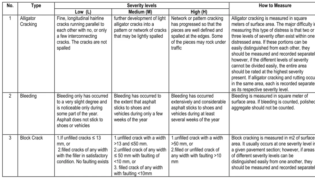
Nineteen distress images are identified and their types, severity and methods of measurements are shown in Table 1.2 in the Appendix.
These distresses can be summarized as: 1. Alligator Cracking (Fatigue)
2. Bleeding
3. Block Cracking
4. Upheaval and Settlements
5. Corrugation
6. Depression
7. Edge Cracking
8. Lane/Shoulders Drop-off
9. Longitudinal and Transverse cracking
10. Patching
7 12. Potholes 13. Railroad Crossings 14. Raveling 15. Reflection Cracks 16. Rutting 17. Shoving 18. Slippage Cracks 19. Swell
4.1 Alligator Cracking (Fatigue)
Alligator or fatigue cracking is a series of interconnecting cracks caused by fatigue failure of the asphalt concrete surface under repeated traffic loading. Cracking begins at the bottom of the asphalt surface, or stabilized base, where tensile stress and strain are highest under a wheel load. The cracks propagate to the surface initially as a series of parallel longitudinal cracks. After repeated traffic loading, the cracks connect, forming many sided, sharp-angled pieces that develop a pattern resembling chicken wire or the skin of an alligator. The pieces are generally less than 0.5 m on the longest side. Alligator cracking occurs only in areas subjected to repeated traffic loading, such as wheel paths. Pattern-type cracking that occurs over an entire area not subjected to loading is called “block cracking,” which is not a load associated distress.
4.2 Bleeding
Bleeding is a film of bituminous material on the pavement surface that creates a shiny, glasslike, reflecting surface that usually becomes quite sticky. Bleeding is caused by excessive amounts of asphalt cement or tars in the mix, excess application of a bituminous sealant, or low air void content, or a combination thereof. It occurs when asphalt fills the voids of the mix during hot weather and then expands onto the pavement surface. Since the bleeding process is not reversible during cold weather, asphalt will accumulate on the surface.
4.3 Block Cracking
Block cracks are interconnected cracks that divide the pavement into approximately rectangular pieces. The blocks may range in size from approximately (0.3) by (0.3) m to (3) by (3) m. Block cracking is caused mainly by shrinkage of the asphalt concrete and daily temperature cycling, which results in daily stress/strain cycling.
8
It is not load-associated. Block cracking usually indicates that the asphalt has hardened significantly. Block cracking normally occurs over a large portion of the pavement area, but sometimes will occur only in non-traffic areas. This type of distress differs from alligator cracking in that alligator cracks form smaller, many-sided pieces with sharp angles. Also, unlike block, alligator cracks are caused by repeated traffic loadings, and therefore, are found only in traffic areas, that is, wheel paths.
4.4Upheaval and Settlements
Upheavals are small, localized, upward displacements of the pavement surface. They are different from shoves in that shoves are caused by unstable pavement. Bumps, on the other hand, can be caused by several factors, including:
Infiltration and buildup of material in a crack in combination with traffic loading (sometimes called “tenting”).
Settlements are small, abrupt, downward displacements of the pavement surface. If bumps appear in a pattern perpendicular to traffic flow and are spaced at less than (3) m, the distress is called corrugation. Distortion and displacement that occur over large areas of the pavement surface, causing large or long dips, or both, in the pavement should be recorded as “swelling.”
4.5 Corrugation
It is a series of closely spaced ridges and valleys (ripples) occurring at fairly regular intervals, usually less than (3) m along the pavement. The ridges are perpendicular to the traffic direction. This type of distress usually is caused by traffic action combined with an unstable pavement surface or base.
4.6 Depression
Depressions are localized pavement surface areas with elevations slightly lower than those of the surrounding pavement. In many instances, light depressions are not noticeable until after a rain, when ponding water creates a “birdbath” area; on dry pavement, depressions can be spotted by looking for stains caused by ponding water. Depressions are created by settlement of the foundation soil or are a result of improper construction. Depressions cause some roughness, and when deep enough or filled with water, can cause hydroplaning.
4.7 Edge Cracking
Edge cracks are parallel to and usually within (0.3) to (0.5) m of the outer edge of the pavement. This distress is accelerated by traffic loading and can be caused by weak base or Subgrade near
9
the edge of the pavement. The area between the crack and pavement edge is classified as raveled if it is broken up (sometimes to the extent that pieces are removed).
4.8 Lane/Shoulders Drop-off
Lane/shoulder drop-off is a difference in elevation between the pavement edge and the shoulder. This distress is caused by shoulder erosion, shoulder settlement, or by building up the roadway without adjusting the shoulder level.
4.9 Longitudinal and Transverse cracking
Longitudinal cracks are parallel to the pavement’s centerline or lay down direction. They may be caused by:
• A poorly constructed paving lane joint.
• Shrinkage of the AC surface due to low temperatures or hardening of the asphalt, or daily temperature cycling, or both.
• Transverse cracks extend across the pavement at approximately right angles to the pavement centerline or direction of lay down. These types of cracks are not usually load-associated.
4.10 Patching
A patch is an area of pavement that has been replaced with new material to repair the existing pavement. A patch is considered a defect no matter how well it is performing (a patched area or adjacent area usually does not perform as well as an original pavement section). Generally, some roughness is associated with this distress.
4.11 Polishing
This distress is caused by repeated traffic applications. Polished aggregate is present when close examination of a pavement reveals that the portion of aggregate extending above the asphalt is either very small, or there are no rough or angular aggregate particles to provide good skid resistance. When the aggregate in the surface becomes smooth to the touch, adhesion with vehicle tires is considerably reduced. When the portion of aggregate extending above the surface is small, the pavement texture does not significantly contribute to reducing vehicle speed.
This type of distress is indicated when the number on a skid resistance test is low or has dropped significantly from a previous rating. No degrees of severity are defined; however, the degree of polishing should be clearly evident in the sample unit in that the aggregate surface should be smooth to the touch.
10 4.12 Potholes
Potholes are small - usually less than (760) mm in diameter - bowl-shaped depressions in the pavement surface. They generally have sharp edges and vertical sides near the top of the hole. When holes are created by high-severity alligator cracking, they should be identified as potholes, not as weathering.
4.13 Railroad Crossings
Railroad crossing defects are depressions or bumps around, or between tracks, or both.
4.14 Raveling
Weathering and raveling are the wearing away of the pavement surface due to a loss of asphalt or tar binder and dislodged aggregate particles. These distresses indicate that either the asphalt binder has hardened appreciably or that a poor-quality mixture is present. In addition, raveling may be caused by certain types of traffic, for example, tracked vehicles. Softening of the surface and dislodging of the aggregates due to oil spillage also are included under raveling.
4.15 Reflection Cracks
This distress occurs only on asphalt surfaced pavements that have been laid over a PCC slab and include reflection cracks from any other type of base, that is, cement- or lime-stabilized; these cracks are caused mainly by thermal- or moisture-induced movement of the pavement layer beneath the AC surface. This distress is not load-related; however, traffic loading may cause a breakdown of the AC surface near the crack. If the pavement is fragmented along a crack, the crack is said to be spalled.
4.16 Rutting
A rut is a surface depression in the wheel paths. Pavement uplift may occur along the sides of the rut, but, in many instances, ruts are noticeable only after a rainfall when the paths are filled with water.
Rutting stems from a permanent deformation, in any of the pavement layers or Subgrade, usually, caused by consolidated or lateral movement of the materials due to traffic load.
4.17 Shoving
Shoving is a permanent, longitudinal displacement of a localized area of the pavement surface caused by traffic loading. When traffic pushes against the pavement, it produces a short, abrupt wave in the pavement surface. This distress normally occurs often in unstable liquid asphalt mix (cutback or emulsion) pavements.
11 4.18 Slippage Cracks
Slippage cracks are crescent or half moon shaped cracks, usually transverse to the direction of travel. They are produced when braking or turning wheels cause the pavement surface to slide or deform. This distress usually occurs in overlaps when there is a poor bond between the surface and the next layer of the pavement structure.
4.19 Swell
Swell is characterized by an upward bulge in the pavement’s surface, a long, gradual wave more than (3) m long. Swelling can be accompanied by surface cracking.
This distress usually is caused by frost action in the Subgrade or by swelling soil.
5. Distress Measurements
5. 1 Distresses Measured by Ride Quality
Ride quality must be evaluated in order to establish a severity level only for the following distress types:
• Bumps. • Corrugation. • Railroad crossings. • Shoving.
To determine the effect of these distresses on ride quality, the inspector should drive at the normal operating speed and use the following severity-level definitions of ride quality:
Low Severity (L): Vehicle vibrations, for example, from corrugation, are noticeable, but no reduction in speed is necessary for comfort or safety. Individual bumps or settlements, or both, cause the vehicle to bounce slightly, but create little discomfort.
Medium Severity (M): Vehicle vibrations are significant and some reduction in speed is necessary for safety and Comfort. Individual bumps or settlements, or both, cause the vehicle to bounce significantly, creating some discomfort.
High Severity (H): Vehicle vibrations are so excessive that speed must be reduced considerably for safety and comfort. Individual bumps or settlements, or both, cause the vehicle to bounce excessively, creating substantial discomfort, safety hazard, or high potential vehicle damage. The inspector should drive a car at the normal speed in a representative section during normal traffic
12
flow. Pavement sections near stop signs should be rated at a deceleration speed appropriate for the intersection.
5.2 Other Types of Distresses
Excluding Bumps, Corrugation, Railroad crossings and Shoving all other types of distress either measured in linear meter or square meter.
Table 1.2 shows the method of measurements of the different distress types of asphalt pavement.
6. Distress Identification and Rating Procedure 6.1 Sampling and Sample Units
The following procedure shall be followed in order to identify branches of the pavement with different uses such as roadways on the network layout plan.
Divide each branch into sections based on the pavements design, construction history, traffic, condition and according to network coding and numbering system.
Divide the pavement sections into sample units. Individual sample units to be inspected should be marked or identified in a manner to allow inspectors and quality control personnel to easily locate them on the pavement surface. Paint marks along the edge and sketches with locations connected to physical pavement features are acceptable. It is necessary to be able to accurately relocate the sample units to allow verification of current distress data, to examine changes in condition with time of a particular sample unit, and to enable future inspections of the same sample unit if desired. Select the sample units to be inspected. The number of sample units to be inspected may vary from the following: all of the sample units in the section, a number of sample units that provides a (95%) confidence level, or a lesser number.
The minimum number of sample units (n) that must be surveyed within a given section to obtain a statistically adequate estimate (95 % confidence) of the PCI of the section is calculated using the following formula and rounding (n) to the next highest whole number (see equation 1-1).
n
NS
2/((
e
2/
4
)(
N
1
)
S
2)
-(1-1) Where,e = acceptable error in estimating the section PCI; commonly, e = ±5 PCI points; s = standard deviation of the PCI from one sample unit to another within the section.
13
When performing the initial inspection the standard deviation is assumed to be ten for AC pavements. This assumption should be checked as described below after PCI values are determined. For subsequent inspections, the standard deviation from the preceding inspection should be used to determine n; and,
N = total number of sample units in the section.
f obtaining the 95 % confidence level is critical, the adequacy of the number of sample units surveyed must be confirmed.
The number of sample units was estimated based on an assumed standard deviation as recommended by ASTM Standard.
n t s iPCI
n
PCI
S
1 2 / 1 2))
1
/(
)
(
(
- (1-2) Where:PCIi = PCI of surveyed sample units i,
PCIs = PCI of section (mean PCI of surveyed sample units), and n = total number of sample units surveyed.
Fig 1.1: Pavement Condition Index (PCI) and Rating Scale Source: ASTM Standard D6433, 2003
14
Individually inspect each sample unit chosen. Sketch the sample unit, including orientation. Record the branch and section number and the number and type of the sample unit (random or additional). Record the sample unit size measured with the hand odometer or measuring tape. Once the number of sample units to be inspected has been determined, compute the spacing interval of the units using systematic random sampling. Samples are spaced equally throughout the section with the first sample selected at random.
The spacing interval (I) of the units to be sampled is calculated by the following formula rounded to the next lowest whole number:
I
N
/
n
- (1-3) Where:N = total number of sample units in the section, and n = number of sample units to be inspected.
The first sample unit to be inspected is selected at random from sample units (1) through (i). The sample units within a section that are successive increments of the interval after the first randomly selected unit also are inspected. Additional sample units only to be inspected when no representative distresses are observed as defined before. These sample units are selected by the user.
Conduct the distress inspection by walking over the sidewalk/shoulder of the sample unit being surveyed, measuring the quantity of each severity level of every distress type present, and recording the data. Each distress must correspond in type and severity to that described in this methodology the method of measurement is included with each distress description. Repeat this procedure for each sample unit to be inspected.
1. Add up the total quantity of each distress type at each severity level, and record them in the “Total Severities” section. For example, Table 1.3 shows five entries for the alligator cracking, edge cracking, patching, potholes and rutting with different severities. The distress at each severity level is summed and entered in the “Total Severity” of low severity or medium severity or high severities. The units for the quantities shall be in square meters, linear meters, or number of occurrences, depending on the distress type.
2. Divide the total quantity of each distress type at each severity level as determined above by the total area of the sample unit and multiply by 100 to obtain the percent density of each distress type and severity.
15
3. Determine the deduct value (DV) for each distress type and severity level combination from the distress deduct value equations in Appendix.
4. Determine the Maximum Corrected Deduct value (CDV) according to the following procedure: • If none or only one individual deduct value is greater than two, the total value is used in place of the maximum CDV in determining the PCI; otherwise, maximum CDV must be determined using the procedure described in the following.
• List the individual deducts values in descending order. For example, in Table 1.5 this will be 25, 20, 8,7,5,4 and 3.
• Determine the allowable number of deducts (m), using the following (1-4):
PCI
S
(
N
A
)(
PCI
R)
/
N
A
(
PCI
A)
/
N
- (1-4) Where:m = Allowable number of deducts including fractions (must be less than or equal to ten), and HDV = Highest individual deduct value.
For example in Table 1.4, m = 1 + (9/98) (100-25) = 7.9).
The number of the individual deduct values is reduced to the (m) largest deduct values, including the fractional part. For example in Table 1.3, the values are 25, 20, 8, 7, 5, 4 and 3 (the number of deduct values available in this example is less than (m) deduct values, in this case use all of the deduct values without a reduction of the last deduct value, (see Table 1).
In the second case ( using data Table 1.5), the number of deduct values will be greater than the (m) value, the reduction shall be calculated as follows: reduce the last value by multiplying it with the difference between calculated (m) value and the number of deduct values less than the allowable ones, (See Table 1.6).
1. Determine total deduct value by summing individual deduct values. The total deduct value is obtained by adding the individual deduct values in Example (1) is (72) and in Example (2) is = (88.7).
2. Determine q as the number of deducts with a value greater than 2.0. For examples in Table 1.3 = 7 and in Table 1.5, q =8.
3. Determine the CDV from total deduct value and (q) by looking up the appropriate correction curve for asphalt concrete pavements in Fig. 20 in Appendix
16
4. Reduce the smallest individual deduct value greater than 2.0 to 2.0 and repeat the last three steps until q = 1.
5. Maximum CDV is the largest of the CDV.
Calculate PCI by subtracting the maximum CDV from 100: PCI = 100-max CDV.
6.3 Determination of Section PCI
If all surveyed sample units are selected randomly or if every sample unit is surveyed then the PCI of the section is the average of the PCI of the sample units. If additional sample units, as defined in before, are surveyed then a weighted average is used as follows:
N
PCI
A
N
PCI
A
N
PCI
S
(
)(
R)
/
(
A)
/
Where:PCIS = weighted PCI of the section,
N = total number of sample units in the section, A = number of additional sample units,
PCIR = mean PCI of randomly selected sample units, and PCIA = mean PCI of additional selected sample units.
Determine the overall condition rating of the section by using the section PCI and the condition rating scale in Fig. 1.1.
A summary report was developed for each section. The summary lists all section location, size, total number of sample units, the sample units inspected, the PCIs obtained, the average PCI for the section, and the section condition rating these data shall be stored on the available data base. Note:
m = 1+ (9/98) (100-25)-7.9 < 8
Use highest 7 deducts without a reduction of the eighth deduct Because the number of deducts less than the allowable
Max CDV = 41
PCI = (100-Max CDV) = 59, Rating = Good Note:
m = 1+ (9/98) (100-25)-7.9 < 8
Use highest 7 deducts and multiply the eighth deduct with the difference of (7.9-7) = 0.9x3= 2.7 Max CDV = 48
17 6.4 Analysis of the Results
Four groups composed of (15) persons were selected for the implementation of this survey. The survey personnel attained training course for three days as part of this research in order to be familiar with the survey methodology and data collection, then the survey starts at the same days in each section previously determined using the adopted methodology presented in this chapter. The survey includes (33) sections from the road network with total length of (2782) km; the survey covers at least (60%) from the length of each section in order to assure the reliability of the data. The visual condition survey is completed in (21) days and the row data were collected, analyzed, and interpreted and the results are presented hereafter.
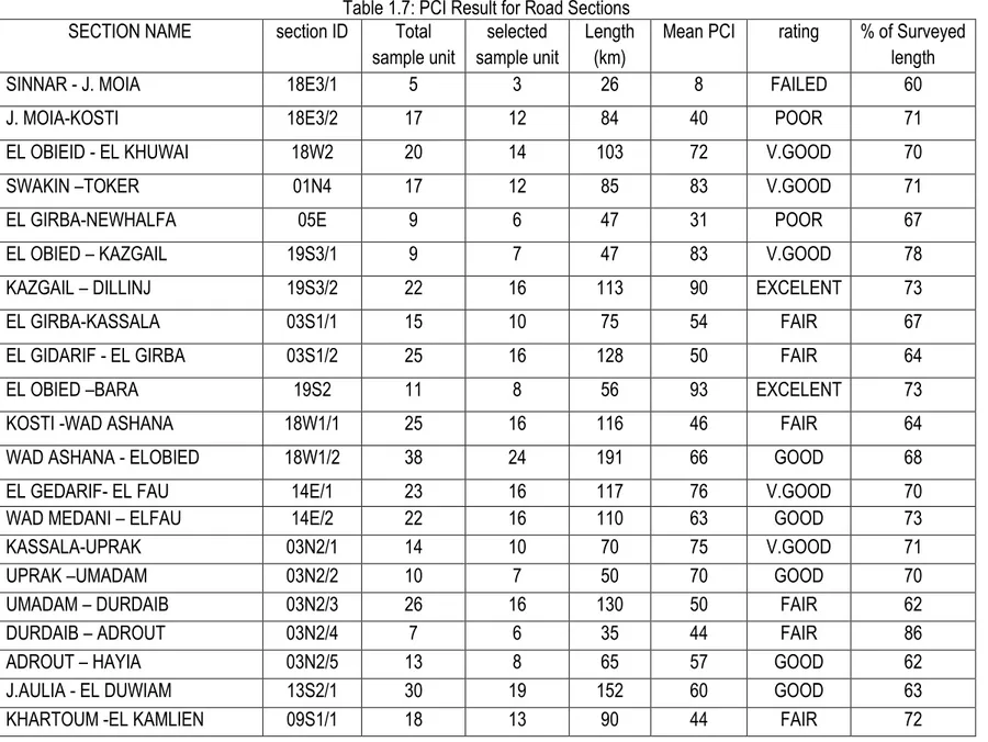
Table 1.7 shows the PCI values for the road sections included in this study, Figure 1.2 shows the average pavement condition index (PCI) value in each road link, Figure 1.3 shows the relative percentage of each distress compared to the paved surface area of all length covered by the visual survey.
The results of the Visual Condition Survey presented in the above figures and graphs reveal the following:
- 17.4 % of the road length (482 km) subjected to visual condition evaluation their condition is failed to very poor and it needs urgent rehabilitation or overlay.
- 20.6 % of road length (574) km is in fair condition. - 22.9 % of road length (638) km is in good condition.
- 39.1 % of road length (1088) km is in satisfactory condition (excellent to very good). Table 1.8 shows that some distress are of low percentage coverage (less than 0.05%) relative to total area of all roads these are slippage cracks, swelling, corrugations and upheaval and settlement. And some other distresses cover large percent of road surface area like raveling, block cracks and bleeding (more than 2 %) of total area, however the largest percent of distress was found to be is polishing (4.3%) as percent of surface area and the lane/shoulder drop off (21.5%) of the road length each road Figure 1.3 shows the relative percent of distress compared to all surveyed roads surface area.
6.5 Individual Deduct Value Polynomials
The individual Deduct value as in Table 1.3 and Table 1.4 is recalculated using the polynomial equations generated using Excel software are listed in Appendix These equations show high reliability (R2 value in each equation is 0.99). Derivation of these equations will ease the tasks for
18
further analysis and developing of visual condition analysis oracle database (software). The use of software will contribute positively in the pavement condition prediction and the results can be presented using Geographical Information System (GIS). As an example Table 1.9 shows analysis of distress type and density data and the degree of correlation between the deduct values calculated by polynomial equations and those interpreted from ASTM standard charts.
Conclusion
1. The study shows that there are 17.4% of the roads are in bad condition “very poor to failed”; 20.6% of roads are in “fair” condition; 22.9% of roads are in “good” condition; 39.1% of roads are in satisfactory condition (excellent – very good) and the greater percentage of distress in all road sections is found to be the lane/shoulder drop off.
2. The target pavement condition index selected as a threshold or intervention for screening and prioritization is the calculated average condition “fair” at (PCI=57%). All roads sections should be maintained in a condition equal to or greater than this value “Fair Condition”, based on the worst-first objective.
3. The use of PCI for prioritizing the road sections give good results when applied by the NHA, because the methodology adopted in the visual condition survey and in calculation of this index depends on direct measurements of each distress on pavement not on just visual rating. 4. The generated polynomial for deduct value calculation is found to be valid enough to be used instead of charts.
7. Recommendations
1. Comprehensive road inventory should be carried every two years to provide satisfactory pavement data including pavement thickness, drainage, roughness, distress …etc.
2. Oracle data base shall be developed for storing analysis, predicting and modeling the visual pavement inspection data, using the polynomial equation generated for each distress type and severities in this thesis.
3. An effort should be made – in the future- from the National Highway Authority for provision of automated data collection equipments for calibration purposes like, Falling Weight Deflectometer (FWD), Road Profiler (RST or ARAN) and Ground Penetration Radar (GPR) for measurement of pavement deflection or structure number, pavement condition and roughness measurement, and pavement thickness measurements respectively.
19
4. As found from pavement condition survey, greater percentage of distress in all road sections is found to be the lane/shoulder drop off; therefore the national highway Authority should make policy to pave all unpaved shoulder in the paved road sections
5. All road sections having PCI less than 57% should be rehabilitated during the coming two years, and an overlay of (4-5) cm should be constructed over the road sections exhibit “fair” condition after the third year.
6. More researches should be carried in the fields of prioritization methods including first, second and third generation methods.
Table 1.1: Road Section Name and ID Number
NUMBER SECTION NAME SECTION ID LENGTH
( km)
1 SINNAR - J. MOIA 18E3/1 26
2 J. MOIA-KOSTI 18E3/2 84 3 EL OBIEID - EL KHUWAI 18W2 103 4 SWAKIN –TOKER 01N4 85 5 EL GIRBA-NEWHALFA 05E 47 6 EL OBIED – KAZGAIL 19S3/1 47 7 KAZGAIL – DILLINJ 19S3/2 113 8 EL GIRBA-KASSALA 03S1/1 75 9 EL GIDARIF - EL GIRBA 03S1/2 128 10 EL OBIED –BARA 19S2 56
11 KOSTI -WAD ASHANA 18W1/1 116
12 WAD ASHANA - ELOBIED 18W1/2 191
13 EL GEDARIF- EL FAU 14E/1 117
14 WAD MEDANI – ELFAU 14E/2 110
15 KASSALA-UPRAK 03N2/1 70 16 UPRAK –UMADAM 03N2/2 50 17 UMADAM – DURDAIB 03N2/3 130 18 DURDAIB – ADROUT 03N2/4 35 19 ADROUT – HAYIA 03N2/5 65 20 J.AULIA - EL DUWIAM 13S2/1 152
21 KHARTOUM -EL KAMLIEN 09S1/1 90
22 EL KAMLIEN -WAD MADANI 09S1/2 70
23 EL JAILI-SHENDI 07N5 129
24 SHENDI –ATBARA 07N4 138
25 ATBARA – BARBAR 07N3 35
26 ELDUWAIM-ASALAIA 13S3/1 90
20
28 SINJA-WAD ELNAIAL 09S4/1 87
29 WAD EL NAIAL- DAMZIEN 09S4/2 84
30 SINNAR-SINJA 09S3 65
31 WAD MADANI - SINNAR 09S2 105
32 RABAK -AL JABALIAN 13S4 69
Table .3: Distress Severity and Method of Measurements
No. Type Severity levels How to Measure
Low (L) Medium (M) High (H)
1 Alligator
Cracking Fine, longitudinal hairline cracks running parallel to each other with no, or only a few interconnecting cracks. The cracks are not spalled
further development of light alligator cracks into a pattern or network of cracks that may be lightly spalled
Network or pattern cracking has progressed so that the pieces are well defined and spalled at the edges. Some of the pieces may rock under traffic
Alligator cracking is measured in square meters of surface area. The major difficulty in measuring this type of distress is that two or three levels of severity often exist within one distressed area. If these portions can be easily distinguished from each other, they should be measured and recorded separately; however, if the different levels of severity cannot be divided easily, the entire area should be rated at the highest severity present. If alligator cracking and rutting occur in the same area, each is recorded separately as its respective severity level.
2 Bleeding Bleeding only has occurred
to a very slight degree and is noticeable only during some part of the year. Asphalt does not stick to shoes or vehicles
Bleeding has occurred to the extent that asphalt sticks to shoes and vehicles during only a few weeks of the year
Bleeding has occurred extensively and considerable asphalt sticks to shoes and vehicles during at least several weeks of the year
Bleeding is measured in square meter of surface area. If bleeding is counted, polished aggregate should not be counted.
3 Block Crack 1.If unfilled cracks ≤ 13
mm, or
2.filled cracks of any width with the filler in satisfactory condition. No faulting exists
1.unfilled crack with a width >13 and ≤50 mm.
2.unfilled crack of any width ≤ 50 mm with faulting of <10 mm, or
3. filled crack of any width with faulting <10mm
1.unfilled crack with a width >50 mm, or
2.filled or unfilled crack of any width with faulting >10 mm
Block cracking is measured in m2 of surface area. It usually occurs at one severity level in a given pavement section; however, if areas of different severity levels can be
distinguished easily from one another, they should be measured and recorded separately
No. Type Severity levels How to Measure
Low (L) Medium (M) High (H)
4 Upheaval &
settlement causes low-severity ride quality causes medium-severity ride quality causes high-severity ride quality measured in linear meters. If the bump occurs in combination with a crack, the crack also is recorded.
5 Corrugation Corrugation produces
low-severity ride quality Corrugation produces medium-severity ride quality
Corrugation produces
high-severity ride quality Corrugation is measured in square meters of surface area
6 Depression 13 to 25 mm 25 to 50 mm More than 50 mm Depressions are measured in square meters
of surface area.
7 Edge
Cracking Low or medium cracking with no breakup or raveling Medium cracks with some breakup and raveling Considerable breakup or raveling along the edge Edge cracking is measure in linear meters.
8 Lane / Shoulder
Drop-off the difference in elevation between the pavement edge and shoulder is > 25 mm and< 50 mm
the difference in elevation
is > 50 mm and < 100 mm the difference in elevation is > 100 mm Lane/shoulder drop-off is measured in linear meters.
9 Longitudinal /
Transverse Cracking
1.filled crack width is less than 10 mm, or 2.filled crack of any width (filler in satisfactory condition).
1. .non-filled crack width is greater than or equal to 10 mm and less than 75 mm; 2. non-filled crack is less than or equal to 75 mm surrounded by light and random cracking; or, 3. filled crack of any width surrounded by light cracks
1. any crack filled or unfilled surrounded by medium- or .high-severity random cracking;
2. unfilled crack greater than 75 m; or,
3. a crack of any width where approximately 100 mm of pavement around the crack is severely broken.
Longitudinal and transverse cracks are measured in linear meters. The length and severity of each crack should be recorded. If the crack does not have the same severity level along its entire length, each portion of the crack having a different severity level should be recorded separately.
No. Type Severity levels How to Measure
Low (L) Medium (M) High (H)
and satisfactory. Ride quality is rated as low severity or better
deteriorated, or ride quality is rated as medium
severity, or both
or ride quality is rated as high severity, or both; needs replacement soon
however, if a single patch has areas of differing severity, these areas should be measured and recorded separately.
For example, 2.5 m2 patch may have 1 m2 of medium severity and 1.5 m2 of low severity 11 Polishing No degrees of severity are defined; however, the degree of polishing should be clearly
evident in the sample unit in that the aggregate surface should be smooth to the touch
Polished aggregate is measured in square meters of surface area. If bleeding is counted, polished aggregate should not be counted.
12 Potholes Max. depth of pothole Average diameter 100 - 200 mm 200 - 450 mm 450 to 750 mm 13 to ≤ 25 mm L M > 25 and ≤ 50 mm L M H > 50 mm M M H
If the pothole is more than 750 mm in diameter, the area should be determined in square meter and divided by 0.5 m2 find the equivalent
number of holes. If the depth is 25 mm or less, the holes are considered me ium-severity. If the depth is more than 25 mm, they are considered high-severity
Potholes are measured by counting the number that are low-, medium-, and high-severity and recording them separately.
No. Type Severity levels How to Measure
Low (L) Medium (M) High (H)
Crossings causes low-severity ride quality
medium-severity ride quality severity ride quality
square meters of surface area. If the crossing does not affect ride quality, it should not be counted. Any large bump created by the tracks should be counted as part of the crossing
14 Raveling Aggregate or binder
has started to wear away. In some areas, the surface is starting to pit. In the case of oil spillage, the oil stain can be seen, but the surface is hard and cannot be penetrated with a coin.
Aggregate or binder has worn away. The surface texture is moderately rough and pitted. In the case of oil spillage, the surface is soft and can be penetrated with a coin.
Aggregate or binder has been worn away considerably. The surface texture is very rough and severely pitted. The pitted areas are less than 10 mm in diameter and less than 13 mm deep; pitted areas larger than this are counted as potholes. In the case of oil spillage, the asphalt binder has lost its binding effect and the aggregate has become loose.
Raveling are measured in square meters of surface area
15 Reflection
Cracks 1.Unfilled crack width is less than 10 mm , or 2. filled crack of any width (filler L
satisfactory condition).
1.Unfilled crack width is greater than or equal to 10mm and less than 75 mm; no
2. filled crack less than or equal to 75 mm surrounded by light secondary cracking; or, filled crack of any width surrounded by light secondary cracking
1.Any crack filled or unfilled surrounded by medium or high-severity secondary cracking; unfilled cracks greater than 75 mm or,
2. a crack of any width where approximately100 mm of pavement around the crack are severely raveled or broken
Reflection cracking is measured in linear meters. The length and severity level of each crack should be identified and recorded separately. For example, a crack that is 15 m long may have 3 m of high severity cracks, which are all recorded separately. If a Bump occurs at the reflection crack, it is recorded also.
No. Type Severity levels How to Measure
Low (L) Medium (M) High (H)
rut depth) surface area, and its severity is determined by the mean depth of the rut. The mean rut depth is calculated by laying a straight edge across the rut, measuring its depth along the length of the rut to compute its mean depth in millimeters.
17 Shoving Shove causes
low-severity ride quality
Shove causes medium-severity ride quality
Shove causes high-severity ride quality
Shoves are measured in square meters of surface area. Shoves occurring in patches are rated with the patch, not as a separately
18 Slippage Cracks Average crack width is
< 10 mm
One of the following conditions exists average crack width is ≥ 10 and < 40 mm, or the area around the crack is moderately spalled, or surrounded with secondary cracks.
One of the following conditions exists the average crack width is > 40 mm, or the area around the crack is broken into easily removed pieces.
The area associated with a given slippage crack is measured in square meters and rated according to the highest level of severity in the area.
19 Swelling Swell causes low severity
ride quality. Low severity swells are not always easy to see but can be detected by driving at the speed limit over the pavement section. An upward motion will occur at the swell if it is present.
Swell causes medium-severity ride quality.
Swell causes high-severity ride quality.
The surface area of the swell is measured in square meters
Table 1-3: Sample unit……… Section……… Link ... Sample area……… Date ……… Surveyed by:…... 15. Reflection Cracks 16. Rutting 17. Shoving 18. Slippage cracks 19. Swell 10. Patching 11. Polishing 12. Potholes 13. Rail/Road cross. 14. Raveling 5. Corrugation 6. Depression 7. Edge cracks 8. Lane/shoulder drop off
9. Long. & Trans. Cracks 1. Alligator cracks 2. Bleeding 3. Block cracks 4. Upheaval & Settlement Deduct value Density % Total Quantity Distress Severity 7 0.56 3.9 1X1.2 1X1.2 1X1.5 1L 25 0.67 4.7 1X2 1X2.7 1H 4 3.1 22 4 6 5 7 8L 20 0.94 6.6 2X1.5 3X1.2 10H 3 0.14 1 1 12L 8 0.96 6.7 2.5X1 3X1 1X1.2 18L 5 12 84 84X1 14L 100 M
Table 1.4: Follow Example (1) Calculation CDV q Total Deduct Values No. 34 7 72 3 4 5 7 8 20 25 1 32 6 71 2 4 5 7 8 20 25 2 35 5 69 2 2 5 7 8 20 25 3 37 4 66 2 2 2 7 8 20 25 4 39.5 3 61 2 2 2 2 8 20 25 5 41 2 55 2 2 2 2 2 20 25 6 35 1 37 2 2 2 2 2 2 25 7 8 9 10 Notes:
- (Y) Parameter in the following 57 equations is the required deduct value and the (X) parameter is the log of the distress density at each case of severity Low, Medium & high.
- The degree of reliability between the original ASTM standard curves and the curves drawn by derived 57 equations., is illustrated by the R2 values for each curve which is minimum value is 99%
(1) Alligator Cracks Deduct Values Calculation at Low (L), Medium (M) & high (H) Severity Equations
y L= 1.397x4 - 4.6379x3 + 6.8218x2 + 19.384x + 10.585 yM = -0.0638x4 - 0.5927x3 + 5.2326x2 + 20.517x + 21.755 yH = 1.5001x4 - 5.5434x3 + 5.0192x2 + 30.77x + 30.71
(2) Bleeding Deduct Values Calculation at Low (L), Medium (M) & high (H) Severity Equations yL = 0.4393x4 + 0.853x3 + 1.0064x2 + 0.9359x + 0.3221
yM = -0.6454x4 + 2.4842x3 + 5.1154x2 + 3.9666x + 2.3776 y H= -0.9966x4 + 4.7297x3 + 8.153x2 + 6.0005x + 5.5388
(3) Block Cracks Deduct Values Calculation at Low (L), Medium (M) & high (H) Severity Equations
y L= 0.0656x4 + 0.7511x3 + 3.3785x2 + 3.3583x + 0.6692 y M= 0.1336x4 - 0.36x3 + 5.5667x2 + 8.8723x + 2.797 yH = -1.1616x4 + 2.6643x3 + 9.4188x2 + 12.475x + 6.8307
(4) Upheaval & settlement Deduct Values Calculation at Low (L), Medium (M) & high (H) Severity Equations
y L= 0.2632x4 + 7.4952x3 + 0.7129x2 + 6.0943x + 3.3233 yM = 9.4947x4 - 7.8903x3 + 8.3794x2 + 18.892x + 12.065 yH = -1.0613x4 + 6.6118x3 + 1.6375x2 + 29.948x + 34.919
(5) Corrugation Deduct Values Calculation at Low (L), Medium (M) & high (H) Severity Equations
y L= -0.697x4 + 2.292x3 + 5.2715x2 + 4.4065x + 2.0851 y M= 0.8146x4 - 2.2378x3 + 5.6499x2 + 19.983x + 15.292 yH= -1.6381x4 + 3.0978x3 + 3.9497x2 + 22.562x + 33.367
(6) Depression Deduct Values Calculation at Low (L), Medium (M) & high (H) Severity Equations
y L= -4.2595x4 + 8.3212x3 + 12.058x2 - 0.2915x + 3.1068 yM = -5.2644x4 + 8.3357x3 + 16.161x2 + 2.5143x + 7.9068 yH = -5.717x4 + 8.3319x3 + 17.178x2 + 7.0203x + 15.895
(7) Edge Cracks Deduct Values Calculation at Low (L), Medium (M) & high (H) Severity Equations
yL = 0.7172x4 + 0.3921x3 - 0.4611x2 + 3.1783x + 1.5663 yM = -1.5729x4 + 3.1185x3 + 4.7354x2 + 3.479x + 4.9747 yH = -6.6773x4 + 14.517x3 + 6.5253x2 + 0.9131x + 9.2965
(8) Lane Shoulder Drop off Deduct Values Calculation at Low (L), Medium (M) & high (H) Severity Equations
yL = -6.8547x4 + 28.066x3 - 30.342x2 + 13.471x + 0.1248 yM= 8.0818x4 - 19.476x3 + 22.092x2 - 7.2014x + 4.6611 y H= 0.0774x4 + 5.766x3 + 3.4491x2 - 0.6096x + 6.0547
(9) Longitudinal & Transverse Cracks Deduct Values Calculation at Low (L), Medium (M) & high (H) Severity Equations
yL = -0.8866x4 + 2.5999x3 + 5.1912x2 + 0.4677x - 0.462 yM = -0.7905x4 + 0.4055x3 + 8.6141x2 + 8.0206x + 1.8647 y H= -3.8165x4 + 10.914x3 + 6.7645x2 + 12.295x + 8.3707
(10) Patching Deduct Values Calculation at Low (L), Medium (M) & high (H) Severity Equations yL = 1.7314x4 - 4.4139x3 + 6.2813x2 + 30.347x + 19.97
yM = -2.9537x4 - 0.7005x3 + 17.173x2 + 41.25x + 31.305 yH = -1.2003x4 - 5.1354x3 + 11.916x2 + 47.728x + 51.812
(11) Polishing Deduct Values Calculation at Low (L), Medium (M) & high (H) Severity Equations
(12) Potholes Deduct Values Calculation at Low (L), Medium (M) & high (H) Severity Equations y L= 1.7314x4 - 4.4139x3 + 6.2813x2 + 30.347x + 19.97
y M= -2.9537x4 - 0.7005x3 + 17.173x2 + 41.25x + 31.305 y H= -1.2003x4 - 5.1354x3 + 11.916x2 + 47.728x + 51.812
(13) Rail – Road Crossing Deduct Values Calculation at Low (L), Medium (M) & high (H) Severity Equations
y L= -8.4612x4 + 15.399x3 + 5.4898x2 - 2.3181x + 2.0393 y M= 24.898x4 - 85.837x3 + 97.372x2 - 5.8123x + 7.1725 yH = 4.3476x4 - 38.532x3 + 63.803x2 + 16.108x + 20.099
(14) Raveling Deduct Values Calculation at Low (L), Medium (M) & high (H) Severity Equations y L= 0.7914x4 - 2.9971x3 + 5.0546x2 + 16.274x + 8.443
yM = 0.4965x4 - 1.6364x3 + 5.6968x2 + 21.002x + 18.157 y H= -0.6792x4 - 1.3087x3 + 7.2891x2 + 27.634x + 26.723
(15) Reflection Cracks Deduct Values Calculation at Low (L), Medium (M) & high (H) Severity Equations
yL = 1.1135x4 - 3.793x3 + 9.0619x2 + 0.5905x - 0.9266 yM = -4.3403x4 + 10.855x3 + 3.1365x2 + 4.4199x + 3.278 yH = -11.755x4 + 29.669x3 + 0.7732x2 + 5.4559x + 8.6428
(16) Rutting Deduct Values Calculation at Low (L), Medium (M) & high (H) Severity Equations y L= 0.367x4 - 1.4838x3 + 5.9195x2 + 11.743x + 3.9726
yM = -1.638x4 + 1.1235x3 + 12.905x2 + 14.999x + 8.7988 y H= -4.2064x4 + 4.0181x3 + 15.537x2 + 18.276x + 17.911
(17) Shoving Deduct Values Calculation at Low (L), Medium (M) & high (H) Severity Equations yL = 0.367x4 - 1.4838x3 + 5.9195x2 + 11.743x + 3.9726
yM = -1.638x4 + 1.1235x3 + 12.905x2 + 14.999x + 8.7988 yH = -4.2064x4 + 4.0181x3 + 15.537x2 + 18.276x + 17.911
(18) Slippage Cracks Deduct Values Calculation at Low (L), Medium (M) & high (H) Severity Equations
yL= 1.492x6 - 2.436x5 - 5.5809x4 + 5.5352x3 + 13.593x2 + 10.681x + 4.2723 y M= 0.3841x6 + 2.0804x5 - 10.367x4 + 1.2921x3 + 22.393x2 + 17.285x + 10.248 y H= 0.7493x6 + 1.5562x5 - 10.762x4 - 3.0824x3 + 26.416x2 + 32.464x + 18.53
(19) Swelling Deduct Values Calculation at Low (L), Medium (M) & high (H) Severity Equations y L= -2.5071x4 + 10.694x3 - 10.967x2 + 14.114x + 0.8957
yM = -2.5653x4 + 7.795x3 - 3.3653x2 + 22.701x + 11.012 y H= -15.364x4 + 46.305x3 - 32.727x2 + 21.848x + 33.0
Table 1.5: Example (2)
Sketch Asphalt Road Condition Survey Data Sheet
Sample unit……… Section……… Link ... Sample area……… Date ……… Surveyed by:…... 15. Reflection Cracks 16. Rutting 17. Shoving 18. Slippage cracks 19. Swell 10. Patching 11. Polishing 12. Potholes 13. Rail/Road cross. 14. Raveling 5. Corrugation 6. Depression 7. Edge cracks 8. Lane/shoulder drop off
9. Long. & Trans. cracks 1. Alligator cracks 2. Bleeding 3. Block cracks 4. Upheaval & Settlement Deduct value Density % Total Quantity Distress Severity 7 0.56 3.9 1X1.2 1X1.2 1X1.5 1L 25 0.67 4.7 1X2 1X2.7 1H 4 3.1 22 4 6 5 7 8L 20 0.94 6.6 2X1.5 3X1.2 10L 3 0.14 1 1 12L 8 0.96 6.7 2.5X1 3X1 1X1.2 18L 5 12 84 84X1 14L 17 1.6 11 5 2 3 7H 100 M 7 M 100 M
Table 1.6: Follow Example (2) Calculation CDV q Total Deduct Values No. 42 8 88.7 2.7 4 5 7 8 17 20 25 1 41 7 88 2 4 5 7 8 17 20 25 2 45 6 86 2 2 5 7 8 17 20 25 3 48 5 83 2 2 2 7 8 17 20 25 4 44 4 78 2 2 2 2 8 17 20 25 5 47 3 72 2 2 2 2 2 17 20 25 6 42.5 2 57 2 2 2 2 2 2 20 25 7 37 1 39 2 2 2 2 2 2 2 25 8 9 10
Table 1.7: PCI Result for Road Sections
SECTION NAME section ID Total
sample unit
selected sample unit
Length (km)
Mean PCI rating % of Surveyed
length
SINNAR - J. MOIA 18E3/1 5 3 26 8 FAILED 60
J. MOIA-KOSTI 18E3/2 17 12 84 40 POOR 71
EL OBIEID - EL KHUWAI 18W2 20 14 103 72 V.GOOD 70
SWAKIN –TOKER 01N4 17 12 85 83 V.GOOD 71
EL GIRBA-NEWHALFA 05E 9 6 47 31 POOR 67
EL OBIED – KAZGAIL 19S3/1 9 7 47 83 V.GOOD 78
KAZGAIL – DILLINJ 19S3/2 22 16 113 90 EXCELENT 73
EL GIRBA-KASSALA 03S1/1 15 10 75 54 FAIR 67
EL GIDARIF - EL GIRBA 03S1/2 25 16 128 50 FAIR 64
EL OBIED –BARA 19S2 11 8 56 93 EXCELENT 73
KOSTI -WAD ASHANA 18W1/1 25 16 116 46 FAIR 64
WAD ASHANA - ELOBIED 18W1/2 38 24 191 66 GOOD 68
EL GEDARIF- EL FAU 14E/1 23 16 117 76 V.GOOD 70
WAD MEDANI – ELFAU 14E/2 22 16 110 63 GOOD 73
KASSALA-UPRAK 03N2/1 14 10 70 75 V.GOOD 71
UPRAK –UMADAM 03N2/2 10 7 50 70 GOOD 70
UMADAM – DURDAIB 03N2/3 26 16 130 50 FAIR 62
DURDAIB – ADROUT 03N2/4 7 6 35 44 FAIR 86
ADROUT – HAYIA 03N2/5 13 8 65 57 GOOD 62
J.AULIA - EL DUWIAM 13S2/1 30 19 152 60 GOOD 63
Table 1.7, (Continued)
SECTION NAME section ID Total
sample unit
selected sample unit
Length (km)
Mean PCI rating % of Surveyed
length
EL KAMLIEN -WAD MADANI 09S1/2 14 10 70 60 GOOD 71
EL JAILI-SHENDI 07N5 25 18 129 82 V.GOOD 72
SHENDI –ATBARA 07N4 27 22 138 85 V.GOOD 81
ATBARA – BARBAR 07N3 7 5 35 87 EXCELENT 71
ELDUWAIM-ASALAIA 13S3/1 18 12 90 92 EXCELENT 67
ASALAIA-RABAK 13S3/2 4 3 20 10 FAILED 75
SINJA-WAD ELNAIAL 09S4/1 17 14 87 23 V.POOR 82
WAD EL NAIAL- DAMZIEN 09S4/2 17 12 84 29 POOR 71
SINNAR-SINJA 09S3 13 9 65 31 POOR 69
WAD MADANI - SINNAR 09S2 21 15 105 90 EXCELENT 71
RABAK -AL JABALIAN 13S4 13 9 69 33 POOR 69
STANDARD DEVIATION OF PCI 24.64
AVERAGE PCI 57.63
34
Table 1.8: Distress Percentages Compared to the Total surface area of Surveyed Roads (2782 km)
Type of Distress % of Distress /total area of 2782 km
ALLIG. CRACKS 1.28 BLOCK CRACKS. 2.20 CORRUGATIONS 0.04 UPHEVAL.& SETTLEMENT 0.03 BLEEDING 2.29 DEPRESSION 0.80 EDGE CRACK 1.81
LANE /SH.DROP 21.5 % of road length
LONG.& TRANS. CR. 1.55 PATCHING 0.48 POLISHING 4.27 RAIL/ROAD CROS. 1.84 POTHOLES 0.13 RAVELING 2.53 REFLECTION CR. 0.15 RUTTING 0.18 SHOVING 0.22 SLIPAGE CRACKS 0.00 SWELLING 0.01
Table 1.9: Correlation between results of polynomial equation and ASTM deduct curve Distress type Density Log density =X Deduct value (polynomial result) =y Deduct value ASTM Difference (R2) 1L 0.56 -0.252 6.216 6.5 -0.2839 0.99 1H 0.67 -0.174 25.538 25 0.5379 8L 3.1 0.491 2.348 2.5 -0.1518 10H 0.94 -0.027 50.538 50 0.5381 12L 0.14 -0.854 2.306 3 -0.6945 18L 0.96 -0.018 4.087 3.5 0.5872 14L 12 1.079 29.199 29 0.1989
35
Figure 1.2: PCI Values on Road Sections
PCI OF ROADS SECTIONS
0 10 20 30 40 50 60 70 80 90 100 S IN N A R J . M O IA J . M O IA -K O S T I E L O B IE ID E L K H U W A I S W A K IN -T O K E R E L G IR B A -N E W H A L F A E L O B IE D K A Z G A IL K A Z G A IL D IL L IN J E L G IR B A -K A S S A L A E L G ID A R IF E L G IR B A E L O B IE D -B A R A K O S T I -W A D A S H A N A W A D A S H A N A E L O B IE D E L G E D A R IF - E L F A U W A D M E D A N I - E L F A U K A S S A L A -U P R A K U P R A K -U M A D A M U M A D A M D U R D A IB D U R D A IB A D R O U T A D R O U T H A Y IA J .A U L IA E L D U W IA M K H A R T O U M -E L K A M L IE N E L K A M L IE N -W A D M A D A N I E L J A IL I-S H E N D I S H E N D I -A T B A R A A T B A R A B A R B A R E L D U W A IM -A S A L A IA A S A L A IA -R A B A K S IN J A -W A D E L N A IA L W A D E L N A IA L - D A M Z IE N S IN N A R -S IN J A W A D M A D A N I - S IN N A R SECTION NAME P C I
36
Figure 1.3: Percent of surface area covered by distresses on the road sections
References
[1] National Highway Authority, “Road sector Management Program Report”, Sponsored by SIDA, Swedish Agency. 2005.
[2] Paterson, W.D., “Choosing an appropriate information system for a Road Management”.
In: PIARC- 19th World congress of PIARC, Marrakesh,. Paris: Permanent International Association of Road Congresses. September 1991.
[3] Deighton, R.A., and Blake, D.G, “Improvement to Utah’s location referencing system to allow data integration”. In: TRB –Third International Conference in Managing Pavements, San Antonio, Texas, 22-25 May 1994, Precedence volume 1. Washington DC: National Academe Press, 97-107. 1994.
[4] Haas,R., “Generically Based Data Needs and Priorities for Pavement Management”, ASTM STP 1121, Frank B., Holt and Wade L. Garmling, Eds., 1992.
[5] Paterson, W. D., “Choosing an appropriate information system for a Road Management”. In: PIARC- 19th World congress of PIARC, Marrakesh. Paris: Permanent International Association of Road Congresses. September 1991.
[6] Robinson, R. Danielsson U., and Snaith M.S, “Road Management: Concepts and Systems”. Basingstoke and London: Palgrave Press, Britain. 1998.
[7] TRL Overseas Unit, “Maintenance Management for District Engineer”, Road Note No. 1,
Crowthorne: Transport and Road Research Laboratory, third Edition. 2003.
[8] OCED, “Road maintenance Management System in Developing Countries”. Paris:
Organization of Economic Co-Operation and Development. 1995.
[9] Ritchie, S.G.et al., “Development of an expert system for pavement rehabilitation decision-making”. Transportation Research Record 1070. Washington DC: Transportation Research Board, 96-103. 1986.
[10] Evdorides, H.T. and Snaith, M.S. Knowledge – based analysis process for road pavement condition assessment’. Proceedings of the Institution of Civil Engineers, Transportation, 117, 202-210. 1996.
37
[11] FHWA, “Federal-Aid Highway Program Manual” Federal Highway Administration, U.S. Department of Transportation, Washington, D.C., March 6, 1989.
[12] M.Y.Shahin, “Pavement Management for Airports, Roads, And Parking Lots”, Chapman and Hall, NY, 1994.
[13] Brooks, D M, R. Robinson and K. P. O'Sullivan. “Priorities in improving road maintenance overseas: a check list for project assessment”. In: Proceedings Institution of Civil Engineers, Part 1, 1989, 86, Dec., 1 12,9- 114 1. 1989.
[14] Robinson, R. Danielson U., and Snaith M.S, “Road Management: Concepts and Systems”. Basingstoke and London: Macmillan Press. 1998.
[15] .Newtech & Norconsult, “Pavement Management System, Data Collection Report” -Sudan. 1992.