Procunier Remodel Project
724 Orinda Ln, Walnut Creek,CA 94597
Jeret Berger Chris Chinn Brooke Lipsey
Architectural Engineering Department
California Polytechnic State University, San Luis Obispo Advisor: Dr. Craig Baltimore, PhD, SE
Table of Contents
Introduction ... 1
Scope of the Report ... 2
Project Introduction and Owner Meeting ... 3
City Coordination and Submittal Requirements ... 5
Architectural Design ... 8
Structural Design ... 12
Estimating Cost ... 17
Scheduling ... 18
Coordinating Consultants ... 19
Appendix A: Cost Estimate ... 20
Appendix B: Submittal Matrix ... 21
Appendix C: Example of Minutes ... 22
Appendix D: Example of Agenda... 24
Appendix E: Architectural Drawings ... 25
List of Figures
Figure 1 - Condition of Existing Foundations……….3
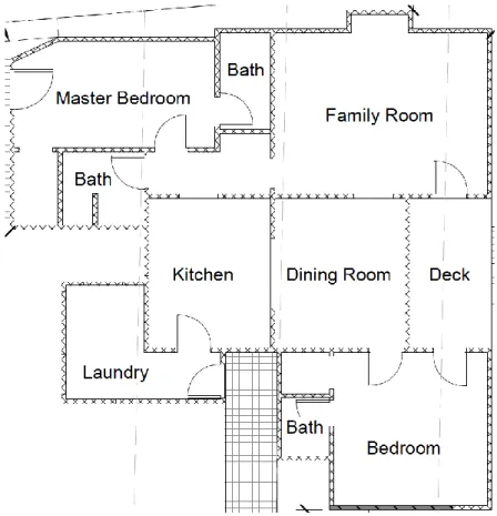
Figure 2 - Floor Plan of Original Structure………..5
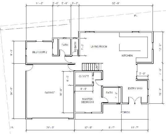
Figure 3 - First Iteration of the First Floor………8
Figure 4 - First Iteration of the Second Floor………..9
Figure 5 - Engineered Wood Joists………13
Figure 6 - Typical Allan Block Retaining Wall………..…14
Figure 7 - Detail of Interior Stair Supports………14
1
Introduction
724 Orinda Lane is a single family home in Walnut Creek, California. Originally built in 1942, the house is currently in a state of disrepair. Time and neglect have created structural issues in the foundation and roof. Uneven settlement has damaged architectural finishes and caused the floors to slope in various directions. Furthermore, the original owner made several additions to the property that left it cluttered and inefficient. The current owner, Nancy Procunier, has decided to remodel the house for her own personal use.
Unlike many senior projects, 724 Orinda Lane represents a real world problem with a client to answer to, a city permitting department to respond to, and professional consultants to
coordinate. In order for this to be a successful project, the team needed to learn how structural engineering fits into the larger scope of construction as a whole. The work went well beyond just creating a structural calculations package and exposed the team to the professional practices of real engineers in the industry.
The goal of the remodel was to create a custom home for Nancy that fit her particular
requirements. These requirements included a separate upstairs quarters for either a caretaker or to rent out as an Airbnb. The only way to accommodate these requests was to perform a complete teardown and rebuild of the original house.
There were two main phases to the project, the design phase and the planning permit phase. The design phase required a site visit as well as continuous communication with Nancy. As the process progressed, acquisition and coordination of consultants became a priority. The planning permit phase played a background role throughout the design process, acting as a guiding hand for major design decisions. Once design was complete, the final task was to ensure that
everything was in accordance with permitting requirements. Finding a city contact in the planning department was critical to avoiding any major hang ups throughout the process.
In order to accomplish the task at hand, work had to be broken down and divided amongst the team. Jeret Buerger, referred to as Jeret in this report, acted as the city contact point. Chris Chinn, referred to as Chris in this report, acted as the construction manager and scribe. Brooke Lipsey, referred to as Brooke in this report, acted as the as the architectural designer as well as the contact point between Nancy and the team. Dr. Craig Baltimore, referred to Dr. Baltimore, was the advisor for this project. The structural design for the project was performed by all group members. Weekly meetings were held in order to keep everyone on schedule as well as to clarify problems and set goals.
2
Scope of the Report
The report is divided into five sections. These sections reflect the disciplines and major events of a building project.
This report summarizes the preconstruction process for a single-family home remodel in the city of Walnut Creek. The first step in this process was for the team to familiarize themselves with the project by performing an initial site visit to see the existing condition and meet the Nancy. She was able to give her vision for the project and the team was able to start an initial
architectural design.
Architectural design was always one step ahead of structural design, similar to professional projects where the architecture drives the structure of a building. The team worked on both sets of drawings simultaneously. Structural calculations moved along hand in hand with the structural drawings.
Throughout the design process, it was critical to coordinate with the many consultants on the project. The first of these consultants contacted were local contractors to confirm the feasibility of the project. Simultaneously, contact was made with the Walnut Creek Planning Department in order to ensure a smooth submittal process. As the project developed, mechanical, electrical, plumbing, and title 24 consultants were brought on in order meet building permit requirements. Clear lines of communication between all of these consultants needed to be developed for this project to succeed.
3
Project Introduction and Owner Meeting
On September 16th, 2017 the team made an initial site visit in order to speak with Nancy about her vision for the project, record dimensions of the existing structure, and assess the overall condition of the house to determine what portions of the house, if any, could be used in the renovated structure.
Upon arrival at the property, the team began to record dimensions of the existing building. Creating existing plans required planning and exhaustive measurement. Since the project site was not local, the number of possible site visits was limited. It was important to get a complete set of measurements the first time. The team meticulously measured each room as well as the exterior of the house. Special care was taken to get accurate distances from the house to the property lines. These measurements were combined to create existing plans, which would later become demolition plans. After an existing floor plan was drawn by hand, the team began to investigate the integrity of the structure.
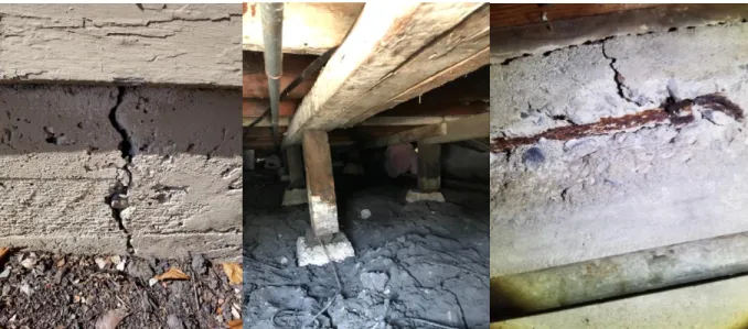
Overall, the house was in poor condition. Apart from the wear and tear that comes with a 70 year old house, there were severe structural concerns. Nancy informed the team that the original owner was a contractor who had made several additions to the house while he lived there. The result was a host of poor construction practices. Large cracks were found throughout the foundation of the house and many of the posts supporting the floor were either completely corroded or were no longer attached to their footings. This created problems with the floor above which was severely warped due to the settlement of the foundation. Upon inspecting the roof framing, it was discovered that there was no actual roof diaphragm connecting the lateral system components. Wood shingles were nailed directly to the rafters. These wood shingles were eventually covered in at least one layer of asphalt shingles.
Figure 1: Condition of Existing Foundations
4
At the end of the site visit, the team had a discussion with Nancy about what she wanted for the project. Nancy had already hired a professional surveyor and was able to provide the team with the completed survey of the property, as well as some original plans of the house.
Originally, the team planned to keep one corner of the front room, about 30 linear feet of wall line, and rebuild the renovated house around these existing walls. However, after seeing the condition of the existing structure, this plan had to be amended to keep just one wall, about 12 linear feet. That being said, this original wall was still in need of repairs and would require not only a new foundation but also a new roof.
5
City Coordination and Submittal Requirements
Communication with the city planning and building departments represented the one of greatest obstacles throughout this process. Since the last day of fall quarter, December 4th, 2017, was the hard deadline for this project, it was important that the team had clear communication with the city in order to ensure that the final submittal was complete.
On August 1st, before the start of the senior project, Nancy had a meeting with representatives from the Walnut Creek planning and building divisions. The team received a copy of the city’s original comments from this meeting. This document outlined areas of concern for the project, and guided the team through the beginning of the project. The City’s main concern was that the existing house was touching the property line on the north end of the plot, and did not comply with the required 10 foot property line offset. The original sketch of the remodel that Nancy brought into the planning division for review placed the remodeled house 3 feet away from this property line. Because this 3 foot offset was short of the 10 foot city minimum, the project would have to be submitted as a ‘variance’ project. Classification as a ‘variance’ project required the team to submit additional documents for review and permitting, including site photographs, a vicinity map, and detailed site plan of the existing and proposed buildings.
6
Haley Croffoot, an associate planner in the Walnut Creek Planning Division who was present at Nancy’s initial meeting, was the primary city contact for the team. The week following the site visit to the property was the first time the team was in touch with a Walnut Creek representative. Based on the city’s comments from the original meeting, the team had a basic understanding of the process of applying for a building permit. On September 20th, Jeret called Haley Croffoot to confirm the team’s understanding of the documents required for submittal.
After talking to the city representative, the team discovered that in order to apply for a building permit from the building division, projects had to first be approved by the planning division. The planning approval process is to verify that the building conforms to zoning requirements, architectural design requirements, and property line offset requirements. After the project is approved by the planning division, a full set of construction documents and structural
calculations can be submitted to the building division for building permitting and construction approval.
This two-phase approval process was an unexpected complication, and required the team to change the parameters of the project. At the start of the project, the original goal was to create a set of construction documents and structural calculations for Nancy to submit for a building permit by the end of December 2017. However, because the city would take roughly 2 months to review and approve the planning submittal, the team would not have enough time to submit for planning approval, receive the approved documents, and then submit for building permit approval. The goal of the project shifted from submitting for a building permit to submitting for planning approval by December 4th and assembling a complete set of construction documents and structural calculations for Nancy to submit for a building permit upon planning division approval. After fall quarter ended, the senior project would be finished but the team would continue to work on the project as consultants as required.
For the most part, the city was responsive to the team’s questions and clarified the required items for approval. In some instances, communication was slow and created a bottleneck in the process: until we heard back from the city about submittal requirements, the team could not advance with the design process. The most notable of these information bottlenecks was the requirements to qualify the project as a ‘remodel’ vs. ‘new construction.’ In order to meet the budget Nancy set, the team needed to confirm that the project would be considered a remodel, which is significantly cheaper than the permitting process for new construction. The primary concern was that the new floor plan, with only 12 feet of the original wall retained from the previous structure, did not retain enough of the existing structure to qualify as a remodel. After multiple phone calls and over a week of waiting for a response, the team found out that because over 50% of the structure would be replaced, the project could not be approved at staff level, and Nancy would have to apply for ‘design review’ in addition to the ‘variance’ submittal.
Applying for design review required another fee as well as additional documents to be submitted with planning approval.
For design review application, a complete set of architectural plans needed to be submitted. In addition to the site photographs, vicinity map, and detailed site plan required for the variance
7
application, the team would also need to provide impervious surface plans, floor plans, roof plans, elevations, architectural details, an arborist report, material samples, and colored drawings. Most of these additional requirements for planning submittal were self-explanatory, but some of the more obscure submittal requirements such as “arborist report” and “material samples” required clarification. As these questions came up, Jeret would call Haley Croffoot and clarify what the city was looking for.
In addition to the architectural constraints from Nancy, the city requirements served as another set of constraints for the project. The submittal requirements guided the team through the design process. Many of the decisions about the exterior dimensions of the house were driven by the property line offset requirements, which in turn affected the interior space and guided some decisions for the layout of rooms. The specific submittables required for approval provided a checklist to go down and served as a barometer to keep the team on track to complete the project. See appendix B for the submittal checklist provided by the city.
8
Architectural Design
Schematic Design
The schematic design phase is period in which the architect and the client work together to define the goals and requirements for the project. From here, an initial rough design can be laid out so the client can see what spatial relationships they prefer.
During the initial site visit to Walnut Creek, the team was able to discuss Nancy's ideas for the remodel. Nancy had several specific elements that she wanted in the new structure, which allowed the design team to start the brainstorming process with those items in mind. Nancy wanted a two story, 3 bed, 3 bath home with the master bedroom upstairs and an open kitchen and living area downstairs. She also requested a two car garage and a deck on the second floor. Initial schematics were drawn out during this meeting to see what floor plan layouts Nancy preferred. With these layouts in mind, the design team left this meeting with a good
understanding of Nancy’s intent for the home and several suggestions of what she hoped to see in the initial design. Her many ideas provided a good outline for the architectural design and allowed the team to find a way to combine all these elements into an aesthetically pleasing, cost effective home.
9
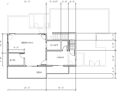
Figure 4: First Iteration of the Second Floor
Design Development
In the design development phase the architect and engineer add more detail to the initial design from the schematic design phase. Plans are solidified and materials and member sizes are chosen.
After this first meeting, the rest of the communication between Nancy and design team was carried out between Brooke and Nancy through email and phone call. Iterations of the drawings were sent via email for Nancy to review and respond to. This worked relatively well with the exception of some struggles trying to describe locations on the plans over phone. Nancy’s lack of architectural vocabulary created some confusion. The team quickly learned to speak very directly and ask lots of clarifying questions to make sure all parties were on the same page regarding design changes.
There were several constraints to keep in mind during the architectural design process. These include, but were not limited to: property line offsets, ensuring safety of oak trees on the property, parking requirements, remodel requirements, cost, and structural stability.
Several of these requirements were mandated by The City of Walnut Creek. As mentioned previously, Nancy had met with the city for a preliminary review. A summary report was created after this meeting and given to the design team. This document communicates the requirement of two parking spaces on the property as well as a variance to allow the house to be 3 feet from the property line. Additionally, through communication with the city, the design team found that the only requirement for a remodel is to keep some part of the existing structure. This can be repair and replace if needed, meaning that the building can be completely demolished as long
10
as one part of the building is rebuilt to match the original structure. The design team decided to repair and replace one wall due to the broken down state of the house.
The most restrictive requirements were cost and structural design. Because of the budget, the team tried to keep the design as efficient as possible. For example, the team attempted to share plumbing walls, walls in which the bathroom and kitchen pipes flow through, with adjacent rooms or rooms above. Additionally, the footprint of the house was generally kept in the same location to limit that amount of excavation for the foundation. Like these examples, many decisions in the design process were driven by price. There were also many limitations due to location of shear walls, the walls that resist wind and earthquake forces. Nancy prefered many openings (windows and doors), which provides less possible shear wall space. This proved to be a problem as Nancy wanted to expand windows after the structural design was finished.
The architectural design went through many iterations and changes, but kept the general layout originally agreed upon in the first meeting. The final design features a great room upon entering with a large living space blending into the kitchen area. The kitchen’s focal point is a large island in the center. Four panel sliding glass doors allow for light to flow in from the side of the house. This great room connects to one bedroom with a bathroom attached in the front of the house and a bedroom and bathroom at the back of the house. Here there is also an entrance to a double car garage as well as the stairway leading to the second story. The second story features an office space with a large window to the front of the house. Attached to this is the master bedroom with a bathroom and walk in closet. Double doors lead out to the deck with exterior stairs down to the side yard. To see the architectural drawings see Appendix E.
Construction Documents
During theconstruction document phase, drawings are developed to the level of detail at which they can be used to construct the building. The drawing packet will included an architectural set of drawings which are described here and a structural set of drawings which are described in the Structural Design section.
The architectural set of drawings included a vicinity map, site plan, floor plans, a roof plan, elevations, 3D views and architectural details. The vicinity map and site plan give an overview of the site showing locations of landscaping, driveways, patios, and building footprints. The floor plans show much of the design information, communicating locations of walls, openings, stairs, and plumbing. The plans also shows the chosen repair and replace wall.
The elevations begin to show the character of the exterior of the building by showing different materials to be used as well as floor heights. The 3D views help the viewer develop a more solid idea of what the building is to look like. Finally, the details clarify some small elements the the design team wanted to specify. These include many flashing details to keep water from settling or getting through cracks. There are also several details showing the layering of materials between walls and floors.
11
The drawings took many hours to complete, however the design team learned the necessity of making sure every detail of these drawings are clear and correct. The drawings will be the only item the design team will pass on to the contractor, so it is imperative that they are easy to understand.
12
Structural Design
Schematic Design
After finishing the architectural design, the team was able to start on the structural design. As mentioned before, the architecture was planned with the location of structural walls in mind. In addition to confirming that the lateral system (structural walls) were sufficient, the foundation, framing system (beams), diaphragm (roofing), stairs, posts, and retaining wall needed to be designed.
Early on the design team asked Nancy which foundation system she would prefer, slab-on-grade or a raised foundation. A raised foundation typically requires excavation to pour the foundations and the erection of a short concrete wall up to the ground level for the floors and walls to be built upon. A slab-on-grade is a type of foundation where a relatively thin layer of concrete is poured under the entire footprint of the house with some areas of thicker concrete where there are heavier loads. The design team explained to Nancy that the slab-on-grade was the least expensive option initially, yet recommended the raised foundation to allow easy access to electrical and plumbing fixtures in case of a repair or modification. Nancy decided on a raised foundation.
Another early decision was to use pre-manufactured trusses. Pre-manufactured trusses are designed by an outside party based on loads given by the engineers. These companies can design and build these trusses very quickly and efficiently. The trusses are relatively
inexpensive because of their ability to use several small members to span long distances. The design team had not used pre-manufactured trusses before, but was aware that most single family homes made use of these trusses because of their efficiency.
Design Development
During the design development phase of the structural design, the team had the opportunity to apply much of their structural engineering knowledge to design a real world structure. This was both and exciting and informative learning experience. The team had to continually design and redesign to meet owner’s needs and create the most efficient system.
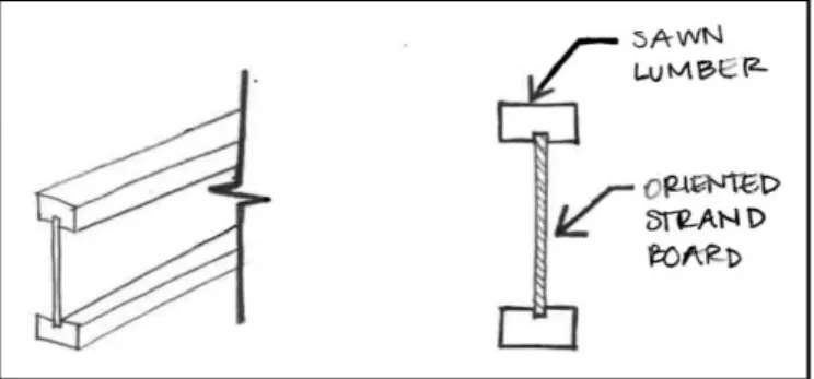
Early on Nancy requested that the noise transfer from footfalls on level two be kept to a
minimum. Based on a recommendation from the design team’s advisor, Dr. Baltimore, the team looked into using engineered wood joists to support the floors. An image of engineered wood joists are shown below. Engineered wood joists limit the amount of creaking in floors as opposed to typical sawn lumber. Sawn lumber begins to creak as it shrinks over time.
Engineered wood joists limit the amount of shrinkage because they are composed of smaller manufactured pieces of wood that shrink less than a large sawn lumber cross section. Because of the efficient shape of the engineered wood joist and the ability to use many small members, they are also able to span further distances. This helped the design team when designing the large first floor open room. Another additional measure that was taken to limit the sound of footfalls was a thick subfloor that acts as a sort of cushion when walking across the floor.
13
Figure 5: Engineered Wood Joists
After an initial layout of the structural framing (the beams and joists supporting the floors) was completed, the design team went through each section and began to design member sizes and connections. While doing this, the team tried to align their design with each previous section that had been designed. The connections became increasingly complicated. The main problem was that the double top plate, the member that lays flat along the top of the wall studs, was
supposed to wrap around the entire building and acts a sort of band. However, in the design the top plate was at different elevations to meet different needs. The design team spent time over two days designing specialized connections so that the force could travel from one top plate to another. After struggling through some of these connections with Dr. Baltimore, he helped the team realize that the design would be much simpler with the top plate all at the same level. After this realization, the complete design of the house became much simpler as well. This is
important because there was now less room for error and a more continuous “band” wrapping around the structure, holding it together. This realization showed the team that questioning your design can lead to a better, more efficient structure.
One unexpected element the design team encountered was the amount of upward wind force on the eaves and overhangs. Based on the design code for wind, the upward wind force overcame the gravity force on the posts. The posts in this project are located on the front patio as well as the second floor deck. The concern was the posts failing in tension as opposed to a typical column where the concern is the post failing in compression. Luckily, the upward wind force was not too strong and the design team was able to use reasonably sized posts.
The team knew that the retaining wall on the west side of the property was going to have to be fairly large. It had to be at least 7 feet tall to hold back the existing soil and also had to support the extra load from the structure on the other side of the property line. After considering these loads and doing some research, the team decided that a block type wall would be more cost efficient than a concrete retaining wall. Similar to the pre-manufactured trusses, the block wall is designed by the manufacturer based on loads provided. This was a simple solution to a large design challenge.
14
Figure 6: Typical Allan Block Retaining Wall
What revealed itself to be one of the more complicated elements of the house was the interior stairs. This may have been attributed to the fact that stairs, unlike many of the other elements in the house, are not covered in the Cal Poly Architectural Engineering design classes. The design team used their knowledge of other structures to come up with a support systems for the stairs that limited movement as people ascended. Some post were required here, but other than that the stairs were supported by the studs already in the walls. This caused these studs to be the most likely to fail because they had the stairs attached, but also extended from the ground floor up to the top of level two. Therefore, the studs were designed for loads coming from the stairs, floor two and the roof at the same time.
Each of these elements posed a new challenge for the design team that they enjoyed working through. With each challenge came a new learning experience that helps to prepare the team for working on projects outside of school.
15
Construction Documents
After the design was established, the team needed to create drawings to communicate the design to the contractor. It was important for each element to be well labeled. This became an issue as there was so much information to fit onto every sheet. One way structural engineers avoid overcrowding of drawings is by referring to details on other sheets. Details show a more complex representation of a certain area on the plans.
Details took the most time of any of the drawings. Working out how to best draw a detail to show every element can often be challenging. Additionally, it is important to show each piece of hardware and appropriately label it. Though it may be the most tedious work, time spent on details can really improve the project. The team learned that details can be the difference between a good and bad quality building. For example, there is a detail of plywood layout around openings to ensure that the typical cracks that occur around openings will not happen over time. Additionally, the stairs are detailed to prevent deflection or movement of the members which in turn limits creaking. Many of the other details show how timber or concrete members joint to other members. These connections are important because the design is only as strong as the connection. Even if a strong beam is chosen it still may not be able to hold much load if there is a bad connection. The structural drawing packet comprised about 50% of the drawings when finished.
A set of general notes also had to be developed for this set of plans. General notes specify any necessary information that does not appear on the drawings and serve as a set of instructions for the contractor. Not only do the general notes specify the quality of materials for the
contractor to use on the project, it notifies the contractor of his responsibilities during construction. These responsibilities range from safe construction site practices to clear
communication with the engineer of record of any problems or changes that may occur during construction. There is a section for each type of material used on the project that lets the contractor know how to properly store, handle, and install each material in order to insure structural integrity.
One element of the construction document phase the team was unfamiliar with was the drawings for the pre-manufactured trusses that were mentioned previously. For the
manufacturers to be able to produce adequate trusses the team had to draw an outline of what they wanted the truss to look like and show the loads that would be acting on the trusses. One of our truss outlines is shown below.
16
Figure 8: Truss Loading Diagram
The design team was very proud of the final set of drawings. It is a great feeling to see all the work you have done summarized into a well drafted packet. The team spent many hours on these drawings making them as clear and precise as possible. To see the structural drawings see Appendix E.
17
Estimating Cost
Cost was the final obstacle that could prevent the remodel from proceeding. It was important to get an accurate estimate early on in the design process in order to make sure the project was actually viable. Nancy had a firm budget that could not be exceeded.
Initially, contact was made with the residential construction professors in the construction management department to see if they had any resources that could help with the estimation process. Unfortunately, none of the professors had any way to estimate the project accurately. They said that the only truly accurate method would be to get pricing information directly from contractors; however, none of the professor knew anyone who could help.
The next attempted method was to contact local contractors directly. Over the next few weeks, emails and calls were sent to over ten firms in Walnut Creek area with very limited success. Of the few firms that responded, only one agreed to speak with the team. In the brief phone call with the one of the firm's managers, while he was driving between job sites, it quickly became apparent that he had neither the time nor the resources to help come up with an estimate for the project. The residential housing market in Walnut Creek was so busy that a half of a million dollar project, which is not a small project, was not worth most contractors’ time. Timing plays a major role in the cost of construction, and at that time it was better to be a contractor rather than an owner.
With limited success and several weeks gone by, it was time for a new approach. Chris
contacted an old boss from a previous internship to see if they knew anyone who could help. It turned out that he knew an estimator, Norman Ho, with experience in Walnut Creek who would be willing to help. Chris reached out Norman and was eventually able to come up with a proper estimate for the project, as seen in Appendix A.
Several weeks later, Nancy received a rough estimate for the project from a contractor bidding the job. To the team’s surprise, the estimate was over 150% of the projected cost. After some research into the current market conditions, it was discovered that demand for contractors was at an all-time high. Companies were up charging significantly simply because they could and there was nothing that the team could do about it. Additionally, a recent fire in the Santa Rosa area had drastically increased the demand for contractors. The fire, called the Tubbs Fire, destroyed 5,636 homes and about half of them were in the city of Santa Rosa, according to Cal Fire Incident Information. The thousands of people displaced by the fire will need places to live and the only way that will happen is if more structures get built. This high level of demand increases the cost of everything from construction labor to raw materials. There are always aspects of a project that are completely out of the control of the team and the fire is good example of one of them. Ultimately it was Nancy’s decision as to whether or not the project would continue to move forward, but if the project was going to get built, it was going to cost a premium.
18
Scheduling
In order to keep the project on schedule, the team started off by meeting biweekly. The first meeting was to set goals for the week and the second meeting was to check on the progress of those goals. The day before each of these meetings, Chris would talk to each team member and come up with an agenda for the following day. An example agenda can be found in Appendix D. Each agenda was separated into two sections, old items and new items. The old items were from past weeks and would include whether or not they had been completed yet. New items came from any new information that the team received from outside consultants or Nancy. The agendas acted as a general measuring tool for progress and gave structure to the meetings.
During each of these weekly meetings, all items on the agenda were discussed and goals for the coming week were set. In order to ensure that nothing that was said was forgotten, Chris acted as the scribe for the meetings and provided minutes. An example of these minutes can be found in Appendix C. In the minutes, tasks were assigned to team members by placing their initials after items that needed to be completed.
As the deadline for the project approached, it became clear that the team was not going to finish at their current rate of work. Dr. Baltimore made the decision to start meeting every day for the last two weeks of the quarter in order to increase productivity. As a result of this decision, the team started to devote more time to the project and substantial progress was made. By December 10th, the entire project had been completed, reviewed, and sent to Nancy.
An important lesson from scheduling this project was that it is important to keep an eye on the final goal. Even though the team had kept up with the original biweekly meetings, the project fell behind. The problem was that the goals set at each of the meetings were not ambitious enough. Additionally, some of the earlier iterative processes, such as general architectural design, continued much longer than originally anticipated. A key skill to have is knowing when
something is good enough to move on. Nothing is perfect in professional design, and the only way projects ever leave the conceptual phase is when someone decides that the design is good enough.
19
Coordinating Consultants
Just like a project in the professional world, this project required the attainment and coordination of consultants. After talking to the city, the team discovered that a stamp would be required for mechanical, electrical, and plumbing plans. A full set of Title 24 calculations would also be required. Outside firms would need to be hired for these work items.
For Title 24, In Balance Green was hired based off of a professor’s recommendation. Dr. Baltimore found Thoma Electric to perform the electrical portion of the design. BMA Mechanical + was hired for the mechanical and plumbing design after being recommended by a local firm. Ideally all of these tasks would have been hired out to a single firm, in order to simplify contracts and communication, but no such firm could be found. Once all of these companies were hired onto the project, all that remained was to coordinate the work.
Coordinating work between three firms had the potential to become very complicated, luckily very few issues arose throughout the entire process. Much of this success had to do with having clear lines of communication. From the start the team was honest about our experience level and made sure to always ask clarifying questions if anything appeared vague. In turn, the firms were generally very responsive and understanding. Keeping everyone on the same page and making sure everyone understood their role on the project kept the work moving smoothly.
20
Appendix A: Cost Estimate
Cost Description Cost Description Cost Description
16.55
CONCRETE
FOUNDATION 0.72 FINISH - HARDWARE 0.00 WARDROBE DOORS
0.00 METHANE BARRIER 5.47 ROOFING 0.43 MIRRORS - MED CABS
0.09 TERMITE PRE-TREAT 0.00 SOLAR 0.33
SHOWER DOORS - TUB ENCLOSURE
18.56 PLUMBING 1.50 INSULATION 0.26 PREP & DETAIL
0.17 SAFETY RAILS 5.10 PAINTING 0.66 FINISH CLEAN
25.94 FRAMING LUMBER 8.01 DRYWALL 1.23 FLOORING - CARPET
3.12 FRAMING TRUSSES 19.82 STUCCO 0.99
FLOORING - CERAMIC TILE
17.34 FRAMING LABOR 0.00 DECK COATING 1.22 FLOORING - HARDWOOD
1.20 ROUGH CLEAN 4.66 CABINETS 0.00 LANDSCAPE
0.00 N/A 0.74 STAIRS 0.00 FINISH GRADING
5.17 WINDOWS 0.00 MASONRY 0.00 FENCING
0.00
WINDOWS
INSTALLATION 0.45 ORNAMENTAL IRON 5.10 Contingency 3%
5.00 ELECTRICAL 0.00 CERAMIC TILE 174.93 TOTAL DIRECTS
2.42 FIRE SPRINKLERS 1.78 GRANITE
7.18 MECHANICAL HVAC 2.78 MARBLE
1.36 FINISH CARPENTRY 0.00 FIREPLACE MANTEL
2.51
MILLWORK - INTERIOR
DOORS 0.69 GARAGE DOORS
1.08
MILLWORK - EXTERIOR
DOORS 1.51
ELECTRICAL FIXTURES
21
22
24
25
27