Abstract
Complex products such as airplanes and automobiles are designed by networks of design teams working on different components, often across organizations. The challenge in managing these networks is to decompose the project into manageable pieces but then coordinate the entire network to produce the best overall design. In this chapter, Manuel Sosa offers insights on this challenge. He examines the design structure matrix (DSM) as a project management tool for planning complex development efforts and discusses the engineering and managerial implications of considering complex products as networks of interconnected subsystems and components. In particular, he considers the impact of modularity on interactions among subcomponents. Finally, he examines organizational communications, overlaying product interfaces with communications interfaces of devel-opment teams to understand where communication links may be missing or unnecessary. The discussion offers insights on any complex design and coordination challenge, where networks of individuals or teams work together to contribute to a larger whole.
Designing new and complex products requires the interplay of processes, products, and structures across networks of individuals and organizations. From a network perspective, processes are networks of design tasks, products are networks of inter-connected components, and organizations are networks of developers or design teams that interact when executing design tasks to develop new products. Because managing
165
Coordination Networks in Product Development
Manuel E. Sosa
interdependences is fundamental to developing new products, taking a network per-spective can advance our understanding of how to coordinate resources in complex development efforts.
Coordination is the result of both system decomposition and system integration. For example, in developing a product such as an airplane, managers decompose the overall project into manageable pieces. Hundreds of specialized cross-functional teams each work on a different component or subsystem of the airplane. Of course, these teams can-not work in isolation; they must integrate and coordinate their efforts to ensure that the system works as a whole. In planning a complex product development process, project managers need to plan and specify just which resources and information different teams will need from each other at particular stages of the project (Sosa, Eppinger, and Rowles 2007b, Sosa 2008).
As we discuss in this chapter, product development managers in large organizations such as Airbus, Ford, or BMW often find themselves lost in their web of design activities and engineering teams, all trying to do the best they can to design their individual piece of the system. Only by taking a network perspective can we navigate the intricate web of activities associated with the design of each of the product components, which is what determines how designers ultimately communicate among themselves during the devel-opment effort.
This chapter is structured in three sections: First, I review the product development literature focused on the use of the design structure matrix (DSM) as a project manage-ment tool that captures developmanage-ment processes as a web of design tasks. Second, I dis-cuss the engineering and managerial implications of considering complex products as networks of interconnected subsystems and components. Finally, I turn to the informal organizational structure to understand how design teams establish and manage their technical communication networks during the design of complex systems.
The Development Process as a Web of Design
Activities
In the early 1980s, BMW used to take about six years to complete a new vehicle development. A particularly important milestone in such a long process used to occur 18 months before product launch. That was the date on which the vehicle concept would be frozen so that detailed engineering could be completed, final prototypes built,
and production ramp-up started. During the development of the first 7 Series in the mid-1980s, managers at BMW decided to widen the entire vehicle by 40 millimeters just two months before completely freezing the design of the car. This, of course, required redesigning more than one-third of the parts in the vehicle. Yet managers at BMW have agreed that, although costly, carrying out such a major design iteration was strictly nec-essary to avoid making the car too “cramped.” Without such a costly decision, the origi-nal 7 Series “would never have succeeded in the market like it has” (Pisano 1996, 6). Although I will not discuss here the specific causes behind this design decision at BMW, this example helps us to illustrate vividly what design iterations are as well as their cost and performance consequences.
Design iterations are the repetition of design tasks due to the arrival of new or more complete information during the development of a new system. Complex products are particularly vulnerable to design iterations because they are complex engineering efforts involving many highly interdependent design activities (Smith and Eppinger 1997b; Mihm, Loch, and Huchzermeier 2003; Sosa, Eppinger, and Rowles 2004). Which design activities are likely to be involved in design iterations? What can managers do to mitigate the negative effects of design iterations? Who is more likely to be involved in design iter-ations? These are some of the questions that product development managers need to address when planning the development of complex systems such as automobile, air-planes, or jet engines.
Traditional project manager tools such as PERT charts and IDEF diagrams have been typically used during the planning of complex projects. However, because these tools have been devised to plan more sequential engineering efforts such as the ones encountered in the construction industry, they are limited in their capability to explicitly portray design iterations (Eppinger 2001). To address such limitations, Steward (1981) introduced a matrix-based tool called the design structure matrix (DSM), which cap-tures the web of design activities in a product development process. Eppinger et al. (1994) extended the use of DSM-based models to improving complex product develop-ment efforts by highlighting the task dependencies that managers can encounter in the process.
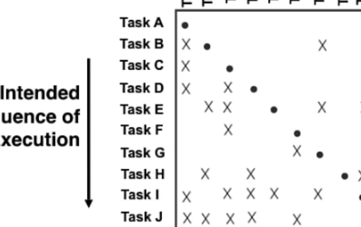
A DSM is a square matrix whose rows and columns are identically labeled with the design tasks of a development process (see Figure 10-1). In its simpler form, the nonzero cells of a DSM indicate the existence of an information requirement between
two development activities. That is, a mark in cell (i,j) indicates that task ineeds
infor-mation produced by task j in order to be completed. Hence, by examining row i of a
by examining column j, managers can easily determine which other tasks are using the
information produced by task j.As a result, the DSM captures in a compact and visual
manner the web of activities that form a development process as determined by the development tasks and their task dependencies. For a review on the various uses of the DSM to improve product development efforts, refer to Eppinger et al. (1994), Eppinger (2001), and Browning (2001).
Figure 10-1 A generic design structure matrix
The DSM also captures the order in which activities are sequenced. Typically, the rows (and columns) are ordered in the chronological sequence in which activities are to be executed, from product planning to product launch. Such a chronological arrange-ment of the rows (and columns) of the DSM allows managers to distinguish between marks below and above the diagonal. Whereas marks below the diagonal are considered feed-forward dependencies because they occur between activities that can be executed in a sequential manner, marks above the diagonal represent feed-back dependencies because they indicate that a design task requires information from another task that will be executed in the future. Therefore, marks above the diagonal represent sources of design iterations because they indicate the arrival of new or updated information that may trigger the rework of a series of design activities. For example, task B in Fig-ure 10-1 would need information from tasks G and J, which are to be executed later in the process. Hence, the arrival of new or updated information to task B may force the team responsible for such a task to revise or rework part of the activities associated with it, which, in turn, can trigger other changes in other design tasks that depend on task B.
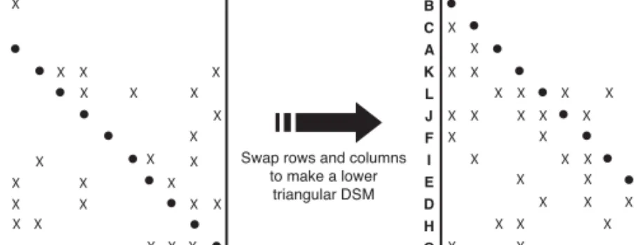
Of course, some of these sources of design iterations can be removed by simply rese-quencing the DSM to minimize marks above the diagonal (Steward 1981; Eppinger et al. 1994), that is, making the development process as sequential as possible (see Figure 10-2). By examining the resequenced (or optimally partitioned) DSM (see Figure 10-3), managers can identify the set of activities that could be executed in a serial fashion (sequential dependency) or those that are independent from each other (parallel dependency). More interesting, managers can also identify the set of design activities that depend on each other in a cyclical manner (coupled dependency). Those are the interdependent (or coupled) development activities that are likely to result in design iterations (Smith and Eppinger 1997a,b).
X X X X X X X X X X X X X X X X X X X X X X X X X X X X X X X A B C D E F G H I J K L A B C D E F G H I J K L X X X X X X X X X X X X X X X X X X X X X X X X X X X X X X B C A K L J F I E D H G B C A K L J F I E D H G
Swap rows and columns to make a lower
triangular DSM
Figure 10-2 Partitioning a DSM into a low triangular DSM
X X X X X X X X X X X X X X X X X X X X X X X X X X X X X X B C A K L J F I E D H G B C A K L J F I E D H G Sequential Parallel Coupled
An Example from Automobile Design
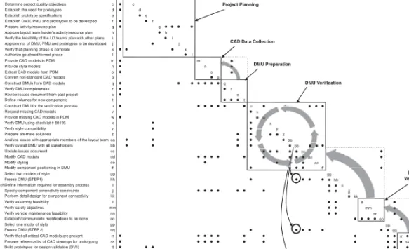
As an example, Ulrich and Eppinger (2004) examine the task structure used by Fiat to develop the digital mock-up of its engine compartments, as shown in Fig-ure 10-4. The blocks along the diagonal of such a DSM highlight the groups of “activities that are executed together (in parallel, sequentially, and/or iteratively) within each phase.” As evident from Figure 10-4, an important contribution of a DSM representa-tion is the simple and explicit representarepresenta-tion of complex and iterative processes in which design iterations can be easily highlighted.
Responsible Activity abcde f ghi j k lmnopqrs t uv wx yz aa bb cc dd ee ff gg hh ii jjkkll mm nn oo pp qq rr ss tt uu vv ww xx Top Management Approve product architecture/configuration aa a
b b m a e t t u o y a l d e d n e t x e e n i f e D r e d a e L m a e T t u o y a L b c s e v i t c e j b o y t il a u q t c e j o r p e n i m r e t e D s m e t s y S c c d s e p y t o t o r p r o f d e e n e h t h s il b a t s E r e d a e L m a e T t u o y a L d d e s n o i t a c i f i c e p s e p y t o t o r p h s il b a t s E s m e t s y S e e
Layout Team Leader Establish DMU, PMU and prototypes to be developed f f f g n a l p e c r u o s e r / y t i v i t c a e r a p e r P r e d a e L m a e T t u o y a L g g
Systems Approve layout team leader's activity/resource plan h h h Planning Verify the feasibility of the LO team's plan with other plans i i I Systems Approve no. of DMU, PMU and prototypes to be developed j j j
k e t e l p m o c s i e s a h p g n i n n a l p t a h t y f i r e V r e d a e L m a e T t u o y a L k k l e s a h p t x e n o t d a e h a o g e z i r o h t u A r o t c e r i D m r o f t a l P l l m M D P n i s l e d o m D A C e d i v o r P g n i r e e n i g n E t n e r r u c n o C m m n s l e d o m e l y t s e d i v o r P r e t n e C g n il y t S n n o M D P m o r f s l e d o m D A C t c a r t x E m a e T t u o y a L e r o C o o p s l e d o m D A C d r a d n a t s -n o n t r e v n o C g n i r e e n i g n E t n e r r u c n o C p p q s l e d o m D A C m o r f s U M D t c u r t s n o C m a e T t u o y a L e r o C q q r s s e n e t e l p m o c U M D y f i r e V m a e T t u o y a L e r o C r r
Layout Team Leader Review issues document from past project s s s t s t n e n o p m o c w e n r o f s e m u l o v e n i f e D m a e T t u o y a L e r o C t t
Core Layout Team Construct DMU for the verification process u u u v s l e d o m D A C g n i s s i m t s e u q e R r e d a e L m a e T t u o y a L v v w M D P n i s l e d o m D A C g n i s s i m e d i v o r P g n i r e e n i g n E t n e r r u c n o C w w x 5 9 1 0 8 # t s il k c e h c g n i s u U M D y f i r e V m a e T t u o y a L e r o C x x y y t il i b i t a p m o c e l y t s y f i r e V m a e T t u o y a L e r o C y y z s n o i t u l o s e t a n r e t l a e r a p e r P m a e T t u o y a L e r o C z z
Core Layout Team Analyze issues with appropriate members of the layout team aa aa aa Extended Layout Team Verify overall DMU with all stakeholders bb bb bb
c c t n e m u c o d s e u s s i e t a d p U m a e T t u o y a L e r o C cc cc d d s l e d o m D A C y f i d o M g n i r e e n i g n E t n e r r u c n o C dd dd e e g n il y t s y f i d o M r e t n e C g n il y t S ee ee f f U M D n i g n i n o i t i s o p t n e n o p m o c y f i d o M m a e T t u o y a L e r o C ff ff g g e l y t s f o s l e d o m o w t t c e l e S t n e m e g a n a M p o T gg gg h h ) 1 P E T S ( U M D e z e e r F m a e T t u o y a L e r o C hh hh
Layout TL/Production TechDefine information required for assembly process ii ii ii Core Layout Team Specify component connectivity constraints jj jj jj Concurrent Engineering Perform detail design for component connectivity kk kk kk
ll y t il i b i s a e f y l b m e s s a y f i r e V y g o l o n h c e T n o i t c u d o r P ll ll m m s e v i t c e j b o y t e f a s y f i r e V r e t n e C y t e f a S mm mm n n y t il i b i s a e f e c n a n e t n i a m e l c i h e v y f i r e V e c n a n e t n i a M e l c i h e V nn nn
Layout Team Leader Establish/communicate modifications to be done oo oo oo p p e l y t s f o l e d o m e n o t c e l e S t n e m e g a n a M p o T pp pp q q ) 2 P E T S ( U M D e z e e r F m a e T t u o y a L e r o C qq qq
Core Layout Team Verify that all critical CAD models are present rr rr rr Core Layout Team Prepare reference list of CAD drawings for prototyping ss ss ss Testing Build prototypes for design validation (DV1) tt tt tt
u u s e p y t o t o r p n o s t n e m i r e p x e n u R g n i t s e T d a o R uu uu v v s e v i t c e j b o y t il a u q t c e j o r p y f i r e V m a e T t u o y a L e r o C vv vv w w e s a h p t x e n o t d a e h a o g e z i r o h t u A r o t c e r i D m r o f t a l P ww ww x x ) 3 P E T S ( U M D e z e e r F m a e T t u o y a L e r o C xx xx abcdef gh j i k lmnopq rs t uvw xy z aa bb cc dd ee ff gg hh ii jjkkll mm nn oo pp qq rr ss tt uu vv ww xx DMU Verification CAD Data Collection
Extended Verifications Project Planning
DMU Preparation
Figure 10-4 Process to develop digital mock-ups at Fiat (courtesy of Steven Eppinger, Ulrich and Eppinger 2004, p. 356;© The McGraw-Hill Companies, Inc.)
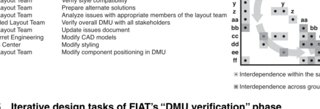
Figure 10-5 provides a closer look at the highly iterative set of activities involved in one phase, “DMU verification.” It shows which organizational group is responsible for executing each design activity. Note that the group of design activities exhibited in Fig-ure 10-5 forms a highly interdependent network of tasks. As a result, managers must pay particular attention to facilitating the information exchanges between the people responsible for this set of activities. Some information exchanges require more manage-rial support than others. In particular, managers have to be more actively involved in
cross-boundary coordination, when iteration is across people from different
Figure 10-5 Iterative design tasks of FIAT’s “DMU verification” phase
In addition to identifying the subset of highly interdependent design activities that are likely to generate design iterations, managers need to understand the specific nature and criticality of the task dependencies of these coupled activities. In the FIAT example, to manage the interdependent design tasks shown in Figure 10-5, managers needed to know which specific engine components and CAD models were involved and how they were connected to one another. In other words, executing the development process shown in Figures 10-4 and 10-5 depends largely on the specific configuration of the product under development, as well as the organization and experience of the people involved. Hence, to effectively manage design iterations in product development, man-agers have to examine the architecture and organizational structure associated with the development process. This approach illustrates how a network view of product and orga-nizational structures can improve the design and execution of complex product develop-ment processes. We now shift our view from the organizational processes to considering the products themselves.
Complex Products as Networks of Components
While complex products result from a network of interlinked design activities, as discussed previously, the products themselves can be seen as networks of intercon-nected components (Simon 1981). Product decomposition determines the architecture of the product, which is the way components interface with each other, so the product can fulfill its functional requirements (Ulrich 1995, Ulrich and Eppinger 2004). More-over, the product architecture results in identifiable design interfaces between its vari-ous components (Henderson and Clark 1990; Ulrich 1995; Sosa, Eppinger, and Rowles 2007a). These interfaces, in turn, are the main source of technical interdependencies
aa bb cc dd ee ff aa bb cc dd ee ff
Core Layout Team Layout Team Leader Concurrent Engineering Core Layout Team Core Layout Team Core Layout Team Core Layout Team Extended Layout Team Core Layout Team Concurret Engineering Styling Center Core Layout Team
Construct DMU for the verification process Request missing CAD models Provide missing CAD models in PDM Verify DMU using checklist #80195 Verify style compatibility Prepare alternate solutions
Analyze issues with appropriate members of the layout team Verify overall DMU with all stakeholders
Update issues document Modify CAD models Modify styling
Modify component positioning in DMU
Responsible Activity
Interdependence within the same group Interdependence across groups
u v w x y z u v w x y z u v w x y z aa bb cc dd ee s c d w
between the design teams responsible for the development of such components, requir-ing coordination between them (Thompson 1967, Galbraith 1973).
Considering products as networks of components has resulted in two important streams of research in engineering design:
1. Product decomposition—Researchers decompose complex products using graphs, trees, and matrices (Michelena and Papalambros 1995; Chen, Ding, and
Li 2005), paying particular attention to the identification of clusters of similarly
dependent components (also called modules) to facilitate integration efforts
dur-ing the design process (Pimmler and Eppdur-inger 1994; Gershenson, Prasad, and Allamneni 1999; Sharman and Yassine 2004).
2. Design change propagation—Researchers also have used product-based DSMs to examine how design changes propagate through interconnected components during the design process (Clarkson, Simons, and Eckert 2004; Eckert, Clarkson, and Zanker 2004). Because components are connected with each other to fulfill the functional requirements of the product as a whole, engineering changes in one component are likely to affect other components.
Although the two areas of research previously described have had a great influence in the way complex engineered products are architected and developed, the focus has been on studying the product network as a whole rather than on structural properties of the components as a function of their connectivity with other components. To address this limitation, Sosa, Eppinger, and Rowles 2007a examine “modularity” of a compo-nent, defined as its level of independence from the other components. By doing so, we
are able not only to quantify component modularity as a function of the lack of
central-ityof the component with respect to other components in the product (Freeman 1979,
Wasserman and Faust 1994), but also to relate how the modularity of product compo-nents relates to important design decisions such as component redesign.
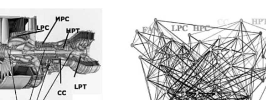
Two important, and challenging, considerations when modeling complex products as networks of components are (1) defining the level of granularity at the node level; and (2) defining the various types of linkages between any two given components. To illus-trate how we have addressed these challenges, consider the architecture of a large com-mercial aircraft engine developed by Pratt & Whitney (Sosa, Eppinger, and Rowles 2003, 2007a). Figure 10-6 shows both a cross-sectional diagram of the engine studied and its network representation. According to our interviews with systems architects at the research site, the engine was decomposed into eight subsystems, each of which was
further decomposed into 5 to 10 components, for a total of 54 components. As a result, there are 54 nodes in the network map shown in Figure 10-6. The nodes are colored to illustrate the eight subsystems that composed the engine: Fan, Low-Pressure Compres-sor (LPC), Pressure CompresCompres-sor (HPC), Combustion Chamber (CC), High-Pressure Turbine (HPT), Low-High-Pressure Turbine (LPT), Mechanical Components (MC), and External and Controls (EC). Because this was the third engine derived from the same basic engine design, the product decomposition into subsystems and components was well understood by our informants, and corresponded with the level of granularity used to establish the organizational structure that designed each of the 54 components. Using a higher level of granularity at the subsystem level would have resulted in a net-work of only eight nodes corresponding to the eight subsystems of the engine, while using a lower level of granularity would have resulted in several hundreds (perhaps thousands) of parts whose individual functionality did not correspond with any impor-tant functional requirement of the engine. Using the engine component, also called
engineering chunks(Ulrich and Eppinger 1994), as the unit of analysis allowed us to
represent the engine based on individual elements associated with important functional requirements with dedicated cross-functional teams responsible for their design and development.
Figure 10-6 Cross-sectional view and network diagram of the PW4098 aircraft engine
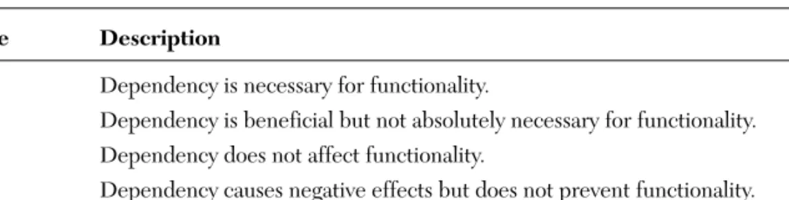
After documenting the general decomposition of the product, we identified the net-work of design dependencies among the 54 components of the engine. We distinguished five types of design dependencies to define the design interfaces (or linkages) of the physical components (see Table 10-1). In addition, we used a five-point scale to capture the level of criticality of each dependency for the overall functionality of the component in question (see Table 10-2), which captures positive or negative design dependencies between components, those that either enable or hinder the component’s functionality
(Jarratt, Clarkson, and Eckert 2004). We consider three levels of criticality: indifferent (0), weak (-1,+1), and strong (-2,+2), because we assume that negative component inter-actions indicate equally important design dependencies to be addressed as positive ones. For additional details on metrics and linkages between product components in complex products, refer to Sosa, Eppinger, and Rowles (2003, 2007a).
TABLE 10-1 Types of Design Dependency Dependency Description
Spatial Functional requirement related to physical adjacency for alignment, orientation,
serviceability, assembly, or weight
Structural Functional requirement related to transferring loads or containment
Material Functional requirement related to transferring airflow, oil, fuel, or water
Energy Functional requirement related to transferring heat, vibration, electric, or noise energy
Information Functional requirement related to transferring signals or controls
TABLE 10-2 Level of Criticality of Design Dependencies Measure Description
(+2) Dependency is necessary for functionality.
(+1) Dependency is beneficial but not absolutely necessary for functionality.
(0) Dependency does not affect functionality.
(-1) Dependency causes negative effects but does not prevent functionality.
(-2) Dependency must be prevented to achieve functionality.
Those components that are less connected to other engine components are more
modularbecause they have more degrees of freedom to fulfill their functional require-ments independently of the state of other engine components. Less modular compo-nents, which are more integrally connected (via nonstandardized interfaces) to other engine components, are more dependent on other components to fulfill their functional requirements. Interestingly, components in complex products exhibit large variation in terms of their interconnectivity within the product. Figure 10-7 shows two engine com-ponents with extreme levels of component modularity.
Figure 10-7 Two engine components with the low and high levels of connectivity
Modularity is important because managers should consider the connectivity of com-ponents with other comcom-ponents when making important design decisions such as out-sourcing or redesigning product components. For example, we found that those components of the engine that were more (directly and indirectly) connected to “trans-mit forces” (an important engine functional requirement) to other components were the ones that exhibited higher levels of component redesign, whereas those components that were more connected due to spatial consideration (an important design constraint) were the ones that exhibited lower levels of component redesign. Hence, the modularity of a component in a complex product can be associated with both high and low levels of component redesign. Managers can use the knowledge of linkages among components
to propagate design decisions or to avoid redesigning some components to prevent
propagating design constraints that could disrupt certain functional requirements of the product (Baldwin and Clark 2000; Sosa, Eppinger, and Rowles 2007a).
In addition to understanding how process networks and networks of components come together in designing complex products such as an airplane or automobile, managers
also have to understand how the organizationactually coordinates the technical interfaces
between the components they design (Allen 1977), as considered in the next section.
The Informal Communication Network of
Design Teams
Communication among design teams working on specific product components is crucial to success, as can be illustrated by two cases. In 1999, the Ford Explorer went from being the number one sport utility vehicle (SUV) sold in USA to the least desired one due to quality problems associated with the suspension system of the Ford Explorer
and the design of its Bridgestone/Firestone tires. Ford and Bridgestone/Firestone lost billions of dollars after their failure to coordinate the vehicle design of the Ford Explorer with the design of its tires (Pinedo, Sehasdri, and Zemel 2000). Similarly, Airbus’s devel-opment of the A380 “superjumbo” suffered major delays and cost overruns because of late-emerging incompatibilities in the design of the electrical harnesses of various sec-tions of the plane’s fuselage. In this case, the electrical harnesses team in Germany and its counterpart team in France, which were responsible for different sections of the fuselage, were not properly communicating about their design interface specifications (Gumbel 2006). These mistakes likely contributed to the resignation of CEOs and the loss of other senior executives’ jobs at both Ford and Airbus.
Although attention to technical interfaces is crucial for successful product develop-ment, teams typically ignore (or pay marginal attention to) a number of interfaces during the development process (Sosa, Eppinger, and Rowles 2004). Some level of neglect is perhaps unavoidable given the cognitive and resource limitations of teams (Simon 1947). Although lack of attention to noncritical or standardized interfaces may not be significant (Sosa, Eppinger, and Rowles 2004), the neglect of critical interfaces can have serious negative consequences (Henderson and Clark 1990).
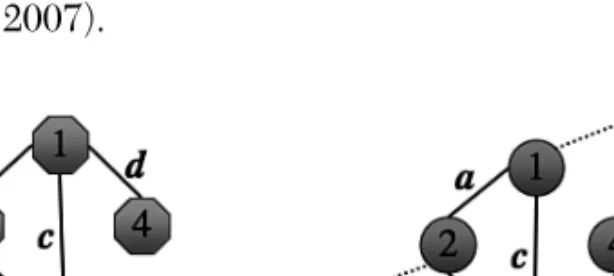
To address this challenge, we need to examine both the architecture of the product and the informal organizational structure. The technical interfaces among product com-ponents define the coordination requirements, and technical communication among design teams constitutes one of the primary coordination mechanisms. Figure 10-8 shows a network of technical interfaces between four components and a network of technical communications between six teams, four of which are in charge of designing these components and two others of which are in charge of integration activities (Sosa, Gargiulo, and C. Rowles 2007).
By superimposing the maps of product interfaces onto the technical communication structure, we can understand where communications links are missing or may be
unnec-essary. Managers can identify not only the technical interfaces that are matchedby
tech-nical team interactions (links a, b,and c) but also the cases of mismatchesof component
interfaces and team interactions. There are two types of mismatches: unmatched
inter-faces,also called unattended interfaces, such as link din Figure 10-8, in which a techni-cal interface is not attended by technitechni-cal communication between corresponding design
teams; and unmatched interactionssuch as link ein Figure 10-8, in which teams
com-municate for technical reasons even though the system architects had not identified
technical interfaces between their components. Finally, there are also external
interac-tionsthat occur when teams that are not directly responsible for the design of a compo-nent interact with teams designing compocompo-nents. This may be the case with teams that are in charge of overseeing the integration among different aspects of the design but are not responsible for designing any specific component, as is the case with teams 5 and 6 in Figure 10-8.
Most of the complex development projects we have studied in the automobile and aerospace industries exhibit this quasi-direct mapping of product architecture and orga-nizational structure; that is, component X is designed by team X with a few system inte-gration teams in charge of evaluating product-level requirements (for example, the fuel economy of an automobile or the weight requirements of an airplane). In some projects such as software development, however, mapping the architecture and organization is far from one-to-one. (In such cases, we can still adapt the approach described in this chapter; refer to Sosa 2008 for details.)
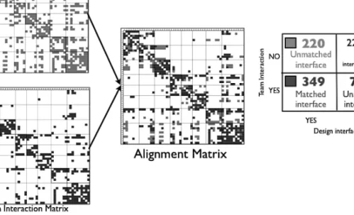
Although Figure 10-8 shows a simple example, overlaying the actual maps of product and organizational interfaces for a product such as the Pratt & Whitney engine we have studied is a daunting task (see Figure 10-9). As a result, we use a matrix representation to compare complex product and organizational networks, as illustrated in Figure 10-10.
Figure 10-10 A structure approach to map product and organizational structures
In this case, a design interface matrixis a 54×54 square with labels corresponding to
the 54 engine components while its nonzero cells correspond to the 569 design
inter-faces among them. In the organizational domain, a similar 54×54 team interaction
matrix captures how the product component teams represented in the rows request technical information from the teams represented in the columns. Note that both
matri-ces are sequenced in a similar manner so that the component labeling row i(and column
i) in the design interface matrix has its corresponding design team labeling row i(and
column i) in the team interaction matrix. Finally, to systematically identify matches and
mismatches of interfaces and interactions, we overlay the design interface matrix and
team interaction matrix to obtain the alignment matrix. Because both design interface
and team interaction matrices are binary matrices, a cell in the alignment matrix has to be a matched interface, an unmatched interface, an unmatched interaction, or a lack of interdependence. (The original team interaction matrix was of size 60 because it included six integration teams, but we excluded these teams from the comparisons of mismatches. We did, however, take these integration teams into account when analyzing the reasons why mismatches occurred.)
As shown in Figure 10-10, 90% of the cases in the alignment matrix were expected cases (either matched interfaces or lack of interdependences), yet the 10% of mis-matched cases are important. Of the 569 design interfaces, 39% of them were unat-tended by team interactions; of the 423 team interactions, over 17% of them were not
associated with design interfaces. Sosa, Eppinger, and Rowles (2004) analyzed the prod-uct and organizational factors associated with the systematic occurrence of these mismatches and found that both interface criticality and group boundary matter signifi-cantly. Most of the unattended interfaces uncovered in the alignment matrix were low-criticality interfaces. The unmatched interfaces and interactions between team boundaries were at higher risk of being both unattended by team interactions and unidentified by system architects. Sosa, Eppinger, and Rowles (2007b) discuss the man-agerial implications of this approach in more detail.
By taking a closer look at design interfaces for specific components, we observed that some components had 100% of their design interfaces attended by team
interac-tions while others exhibited less than 40% of their interfaces attended. Why are some
teams better than others at attending the technical interfaces of the components they design? Is it because of attributes of the components they design, or because of the struc-ture of the communication networks with other teams in the organization, or both?Sosa, Gargiulo, and C. Rowles (2007) found that after controlling for component and team attributes, both the connectivity of product components and the structure of the com-munication network of design teams matter. Interestingly, these network properties matter in different ways depending on whether the focal team acts as a provider or receiver of technical information.
Components appear to have an impact because teams working on highly indirectly
connected components have trouble paying attention to technical requests from others because such teams are the ones more likely to suffer excessive and unforeseeable work-load due to heavy design iterations. The team’s communication network structures also have an effect because, on one hand, teams with sparse communication networks were more likely to search and acquire the technical information about the interfaces of the components they design, and, on the other hand, those teams that were surrounded by a more cohesive communication network structure were the ones that exhibited higher capability to attend the technical requests from other design teams in the network. (This is presumably because such teams enjoyed the benefits of the collaborative environment associated with close and cohesive networks.)
Conclusions and Future Directions
As Simon (1981) suggested, complex systems are difficult to understand because the behavior of the whole depends in nontrivial ways on how its elements interact. This chapter has outlined how a network view of processes, products, and organizations can help us understand how complex product development systems draw together components that form complex systems such as automobiles or aircraft engines. By con-sidering processes not as a sequential set of activities but instead as a web of tasks, some of which can be highly interdependent, we have uncovered the reason design iterations occur. By modeling complex products as networks of interconnected components, we have learned how to cluster components into modules in a more efficient way to make complex systems nearly decomposable systems (Simon 1981). In addition, by taking a network approach to analyzing complex products, we can then consider structural prop-erties of product components that are defined by the patterns of technical interfaces with other components. Finally, by mapping the network of components that form a product with the communication network of teams that design such components, we have been able to evaluate systematically why some interfaces are at higher risk of being unattended than others.
Only by taking a network perspective have we been able to uncover these findings and insights. Yet there is more to learn. Two promising areas in product development that would certainly benefit from a network perspective are product-organizational dynamics and innovation networks. To study the coevolution of product and organizational struc-tures, our current research efforts focus on examining open source software development (Sosa, Browning, and Mihm 2007). One of the advantages of studying the architecture of software products is that their architecture is relatively easy to capture because it is prop-erly codified in their source code (Sangal et al. 2005; MacCormack, Rusnack, and Bald-win 2006). In addition, software products are complex and fast-evolving, which makes them our ideal “fruit flies” to investigate how complex systems evolve over time.
Understanding creativity is imperative for effective innovation management. Cre-ativity is no longer considered an individual attribute but a social activity, yet we are just beginning to understand the role of social networks in the creative process (Fleming, Mingo, and Chen 2007; Sosa 2007). Which attributes of the knowledge exchanged in organizational networks like the ones discussed in this chapter influence creative out-comes? Are more talkative teams more likely to generate more novel and useful ideas than less talkative teams? These are some of the questions innovation managers need to address as they also embark on the challenge of understanding the social networks they are managing.
Finally, as pointed out by Nambisan and Sawhney in Chapter 9, “Network-Centric Innovation: Four Strategies for Tapping the Global Brain,” different models for net-work-centric innovation require different types of coordination and communication. Whether the process is more centralized (such as the Orchestra model) or more decen-tralized (such as the Global Bazaar model) will determine the type of interfaces that are needed in the network of design teams, the level of creativity that is desired, and the types of communication flows.
As product development increasingly depends on networks of design teams,
net-work thinkingwill be a useful capability for managers in building more successful prod-uct development organizations. The frameworks presented in this chapter offer valuable tools for understanding and improving how these networks are structured, communi-cate, and evolve.
References
Allen, T. J. 1977. Managing the Flow of Technology.Cambridge, MA: MIT Press.
Baldwin, C. Y., and K. B. Clark. 2000. Design Rules: Volume 1: The Power of Modularity.
Cambridge, MA: MIT Press.
Browning, T. R. 2001. Applying the design structure matrix to system decomposition
and integration problems: A review and new directions. IEEE Transactions on
Engineering Management48 (3), 292-306.
Chen, L., Z. Ding, and S. Li. 2005. A formal two-phase method for decomposition of
complex design problems. ASME J. Mech. Des.127, 184-195.
Clarkson, P. J., C. S. Simons, and C. M. Eckert. 2004. Predicting change propagation in
complex design. ASME Journal of Mechanical Design126 (5), 765-797.
Eckert, C. M., P. J. Clarkson, and W. Zanker. 2004. Change and customization in
com-plex engineering domains. Research in Engineering Design15 (1), 1-21.
Eppinger, S. D. 2001. Innovation at the speed of information. Harvard Business Review.
Eppinger, S. D., D. E. Whitney, R. P. Smith, and D. A. Gebala. 1994. A model-based
method for organizing tasks in product development. Research in Engineering
Design6 (1), 1-13.
Fleming, L., S. Mingo, and D. Chen. 2007. Brokerage and collaborative creativity.
Freeman, L. 1979. Centrality in social networks. Conceptual clarification. Social Networks1, 215-239.
Galbraith, J. R. 1973. Designing Complex Organizations.Reading, MA: Addison-Wesley
Publishing.
Gershenson, J. K., G. J. Prasad, and S. Allamneni. 1999. Modular product design: A
life-cycle view. Journal of Integrated Design and Process Science3 (4), 13-26
Gumbel, P. 2006. Trying to untangle wires. Time,October 16 (European edition), 36-37.
Henderson, R., and K. Clark. 1990. Architectural innovation: The reconfiguration of
existing product technologies and the failure of established firms. Administrative
Science Quarterly 35 (1), 9-30.
Jarratt, T., J. Clarkson, and C. Eckert. 2005. Engineering Change. In Design Process
ImprovementA Review of Current Practices,266-285.
MacCormack, A., J. Rusnack, and C. Baldwin. 2006. Exploring the structure of complex
software designs: An empirical study of open source and proprietary code.
Manage-ment Science52 (7), 1015-1030.
Michelena, N., and P. Y. Papalambros. 1995. A network reliability approach to optimal
decomposition of design problems. ASME Journal of Mechanical Design 117 (3),
433-440.
Mihm, J., C. Loch, and A. Huchzermeier. 2003. Problem-solving oscillations in complex
engineering projects. Manag. Sci.46 (6), 733-750.
Pimmler, T. U., and S. D. Eppinger. 1994. Integration analysis of product
decomposi-tions. ASME Conference on Design Theory and Methodology,in Minneapolis, MN,
343-351.
Pinedo, M., S. Sehasdri, and E. Zemel. 2000. The Ford-Firestone case. Teaching case.
Department of Information, Operations, and Management Sciences, Stern School of Business, NYU.
Pisano, G. 1996. BMW: The seven series project. HBS case 9-692-083.
Sangal, N., E. Jordan, V. Sinha, and D. Jackson. 2005. Using dependency models to
manage complex software architecture, Proceedings of the 20th Annual ACM
SIG-PLAN Conference on Object Oriented Programming, Systems, Languages, and Applications,in San Diego, CA.
Sharman, D., and A. Yassine. 2004. Characterizing complex products architectures.
Systems Engineering7 (1), 35-60.
Simon, H. A. 1947. Administrative Behavior: A Study of Decision-making Processes in
Administrative Organizations.Chicago, IL: Macmillan.
Simon, H. A. 1981. The Science of the Artificial.2nd ed. Cambridge, MA: MIT Press.
Smith, R. P., and S. D. Eppinger. 1997a. A predictive model of sequential iteration in
engineering design. Manag. Sci.43 (3) 276-293.
Smith, R. P., and S. D. Eppinger. 1997b. Identifying controlling features of engineering
design iteration. Manag. Sci.43 (8) 1104-1120.
Sosa, M. E. 2007. Where do creative interactions come from? The role of tie content
and social networks. INSEAD working paper 2007/49/TOM.
Sosa, M. E. 2008. A structured approach to predicting and managing technical
interac-tions in software development. Research in Engineering Design 19(1) 47-70.
Sosa, M. E., T. Browning, and J. Mihm. 2007. Studying the dynamics of the architecture
of software products. Proceedings of the 19th ASME Design Theory and
Methodol-ogy Conference.
Sosa, M. E., S. D. Eppinger, and C. M. Rowles. 2003. Identifying modular and
integra-tive systems and their impact on design team interactions. ASME Journal of Mech.
Design125 (2), 240-252.
Sosa, M. E., S. D. Eppinger, and C. M. Rowles. 2004. The misalignment of product
architecture and organizational structure in complex product development.
Man-agement Science50 (12), 1674-1689.
Sosa, M. E., S. D. Eppinger, and C. M. Rowles. 2007a. A network approach to define
modularity of components in complex products. ASME Journal of Mechanical
Design129 (11), 1118-1129.
Sosa, M. E., S. D. Eppinger, and C. M. Rowles. 2007b. Are your engineers talking to one
another when they should? Harvard Business Review,November.
Sosa, M. E., M. Gargiulo, and C. Rowles. 2007. Component connectivity, team network structure, and the attention to technical interfaces in complex product development.
INSEAD working paper 68/TOM/OB.
Steward, D. 1981. The design structure matrix: A method for managing the design
of complex systems. IEEE Transactions on Engineering Management EM-28 (3),
Thompson, J. D. 1967. Organizations in Action.New York: McGraw-Hill.
Ulrich, K. T. 1995. The role of product architecture in the manufacturing firm. Res.
Policy.24, 419-440.
Ulrich, K. T., and S. D. Eppinger. 2004. Product Design and Development.3rd ed. New
York: McGraw Hill.
Wasserman, S., and K. Faust. 1994. Social Network Analysis. New York: Cambridge