DOTTORATO DI RICERCA IN INGEGNERIA ELETTROTECNICA
_______________________
Ciclo XXVII
Settore Concorsuale di afferenza:
09E2
Settore Scientifico disciplinare: ING-IND/33
MODELLING AND ANALYSIS OF NETWORKED CONTROL STRATEGIES
IN SMART POWER DISTRIBUTION GRIDS: DEVELOPMENT OF
CO-SIMULATION TOOLS
Presentata da:
RICCARDO BOTTURA
Coordinatore Dottorato
Relatore
Prof. Domenico Casadei
Prof. Alberto Borghetti
Correlatore
Prof. Carlo Alberto Nucci
I
NDEX
EQUATION
CHAPTER
1 SECTION 1
Figure Index ... III
Chapter 1 Introduction ... 1
Chapter 2 ICT and Power System Co-simulation platform ... 5
2.1 Architecture ... 7
2.2 EMTP-RV model ... 8
2.3 OPNET Riverbed programming ... 9
2.4 Illustrative test case ... 11
Chapter 3 Analysis of Communication-based Volt/Var Optimization in Distribution Feeders ... 13
3.1 Aim of the study ... 13
3.2 Volt – Var Optimization (VVO) of distribution feeders ... 14
3.2.1 Multi agent system approaches for VVO ... 14
3.2.2 Implemented Gossip-like VVO Procedure ... 15
3.2.2.1 Evaluation for the reactive power compensation ... 16
3.2.2.2 Subsequent activation of couples of agents ... 21
3.2.2.3 Countermeasures against the loss of packets and communication latency ... 22
3.2.3 Algorithm ... 23
3.2.3.1 Measurement, information exchange and calculation of ΔQ ... 23
3.2.3.2 Implementation of ΔQ ... 24
3.2.3.3 Selection of the new couple of agents ... 25
3.3.1 Communication model ... 26
3.3.2 Power distribution feeder model ... 28
3.3.2.1 Control of the OLTC transformers ... 29
3.3.2.2 Reactive power compensators ... 30
3.3.2.3 Local voltage control function ... 31
3.4 Simulation results ... 32
3.4.1 IEEE 37 Node Test Feeder ... 34
3.4.2 IEEE 123 Node Test Feeder ... 42
3.5 Reactive power control of photovoltaic units over wireless UMTS cellular networks ... 46
3.5.1 Multi-agent PV inverter based voltage/var control ... 47
3.5.1.1 Gossip-Like VVC algorithm adapted for the PV units ... 47
3.5.2 Wireless cellular based ICT – Power System co-simulation platform ... 49
3.5.2.1 UMTS network model ... 50
3.5.3 Power distribution feeder model ... 52
3.5.4 Simulation results ... 53
Chapter 4 Integration of traffic and grid simulator for the analysis of e-mobility impact on power distribution networks ... 59
4.1 Motivation and aim of the research ... 59
4.2 Architecture of the co-simulation platform ... 60
4.2.1 Traffic simulator ... 61
4.2.2 Power distribution system simulator ... 62
4.2.3 Communication network simulator ... 63
4.3 Multi agent system for the distributed control of charging stations ... 63
4.4 Simulation Results ... 65
Chapter 5 Conclusion ... 72
F
IGURE
I
NDEX
Figure 1.1 Smart grid technologies and applications [1] ... 1
Figure 1.2 Illustrative figure of a distribution system with networked monitoring, control and protection devices. [1] ... 2
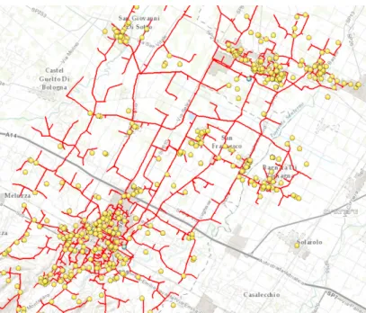
Figure 1.3 Scheme of the medium voltage distribution network of Imola with the indication of clients with generation capability (data curtesy of Hera Multiutility Company). ... 3
Figure 2.1. Architecture of the HLA co-simulation platform. ... 7
Figure 2.2 Synchronization mechanism ... 8
Figure 2.3 - Example of a symbol for a user- defined DLL ... 8
Figure 2.4. a) Extended TCP client-server model; b) esys module associated to the “cosim_client_server” module. ... 9
Figure 2.5 ESD Model ... 10
Figure 2.6. Example of a SD file. ... 10
Figure 2.7. Electrical and corresponding Communication system ... 11
Figure 2.8. Comparison between the behavior of the current at relay 1 for the three scenarios of communication traffic of Table 2.I. ... 12
Figure 3.1 Equivalent network obtained through the Kron’s reduction technique ... 18
Figure 3.2 Agents (red dotted) of the equivalent reduced network equipped with a bus voltage sensor that incorporates the PMU function ... 23
Figure 3.3 Measurement, information exchange from node h to node k – step 3 ... 24
Figure 3.4 Measurement, information exchange, calculation and injection of ΔQ ... 25
Figure 3.5 Correspondent example of bi-directional information exchange in the IEEE 37 and 123 node test feeders ... 25
Figure 3.6 Selection of the new couple of agents ... 26
Figure 3.7. a) TCP and b) UDP extended node models. hub_rx and hub_tx: physical layer; mac (Media Access Control) and arp (Address Resolution Protocol): link layer; ip (Internet Protocol) and ip_encap (which encapsulates packets into IP datagrams): internet layer; tcp or udp and transport_interface: transport layer. ... 27
Figure 3.8 Correspondent Internet based communication network of the IEEE 37 node Test Feeder ... 28
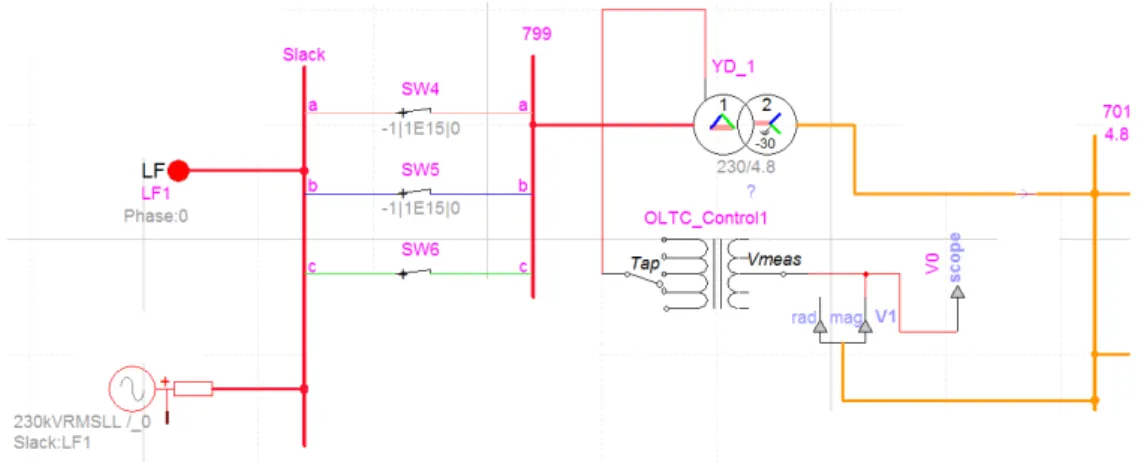
Figure 3.9 EMTP-rv model design of the substation fed by a three-phase voltage generator and control by an OLTC transformer ... 29
Figure 3.10 OLTC model ... 30
Figure 3.11 EMTP-rv model design of the compensators ... 31
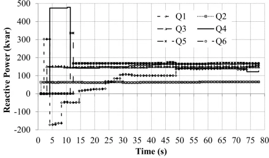
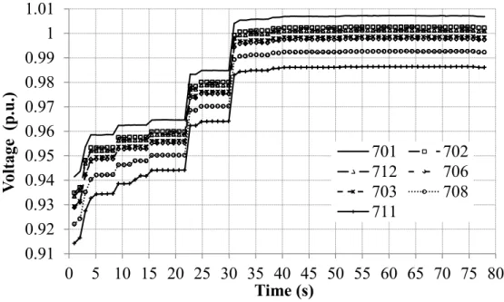
Figure 3.13 TF1: power feeder in black and communication network in red. Red dots indicate the agents associated to compensators whilst the blue one indicates an agent that does not directly adjust the output of any compensator. ... 33 Figure 3.14 TF2: power feeder in black and communication network in red. Red dots indicate the agents associated to compensators whilst the blue ones indicate agents that do not directly adjust the output of any compensator. ... 33 Figure 3.15 Power loss variation in TF1 for different BT levels and PDR by using TCP and UDP. ... 37 Figure 3.16 Variations of reactive power outputs of the compensators in TF1 for BT1-PDR0 case with UDP. ... 38 Figure 3.17 Bus voltage variations in TF1 for BT1-PDR0 case with UDP. ... 38 Figure 3.18 Power loss variation in TF1 with active OLTC for different BT levels and PDR by using TCP and UDP. ... 39 Figure 3.19 Bus voltage variations in TF1 with active OLTC for case BT1-PDR0 with UDP. ... 39 Figure 3.20 Comparison of power loss variation in TF1 with blocked OLTC by using the MAS procedure, by using only the local controllers and by using both regulations (case BT1-PDR0 with UDP). ... 40 Figure 3.21 Comparison of bus voltage variations in TF1 with blocked OLTC by using the MAS procedure, by using only the local controllers and by using both regulations (case BT1-PDR0 with UDP). ... 41 Figure 3.22 Comparison of power loss variation in TF1 with blocked OLTC by using compensators of different size (case BT1-PDR0 with UDP). ... 41 Figure 3.23 Power loss variation in TF2 with blocked OLTCs for two different BT and PDR levels by using TCP and UDP. ... 44 Figure 3.24 Voltage variations in TF2 with blocked OLTCs for BT2 by using UDP. ... 45 Figure 3.25 Power loss variation in TF2 with the OLTCs in operation for two different BT levels by using TCP and UDP. ... 45 Figure 3.26 Voltage variations in TF2 with the OLTCs in operation for BT1 by using UDP. ... 46 Figure 3.27 Active power value Pi determined by the MPPT algorithm [71] ... 49 Figure 3.28 Screenshot during the simulation in debugging mode of the correspondent UMTS
communication model of the IEEE 37 Node Test feeder ... 50 Figure 3.29 Screenshot during the simulation in debugging mode of the correspondent UMTS
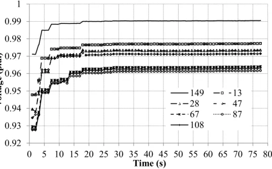
communication model of the IEEE 123 Node Test feeder ... 51 Figure 3.30 Extended UDP node model of UMTS UE. ... 51 Figure 3.31 TF1: one-line diagram of power feeder (in black) and UMTS communication network (dotted red lines represent wireless channels, solid red lines represent wired channels). The dots represent 7 networked controllers (agents). The green circles indicate the estimated coverage areas of the Node B antennas. ... 53 Figure 3.32 TF2: one-line diagram of power feeder, UMTS communication network and location of the agents. ... 54 Figure 3.33 UMTS communication network of the IEEE 37 node test feeder with UEs that send “Mobile User traffic model” to the Interactive Content Receiver and the Gaming app Receiver ... 55 Figure 3.34 UMTS communication network of the IEEE 123 node test feeder with UEs that send “Mobile User traffic model” to the Interactive Content Receiver and the Gaming app Receiver ... 55 Figure 3.35 Power loss variation in TF1 for different BT and BLER levels ... 57
Figure 3.36 Variations of reactive power outputs of the PV inverters of TF1 for BLER0, BT0 and normal load levels ... 58 Figure 3.37 Voltage variations of the PV inverters of TF1 for BLER0, BT0 and normal load levels. ... 58 Figure 4.1 Data exchange between the traffic simulator, the power distribution simulator and
communication network simulator. ... 61 Figure 4.2 Use of the SIB for the exchange of information and the WS for platform synchronization. ... 61 Figure 4.3 a) mobility simulator framework b) example of SUMO environment with correspondent electric vehicle (green), electric vehicle in charging (yellow) and fuel vehicle (red). ... 62 Figure 4.4 EMTP model of the aggregate EVSE ... 62 Figure 4.5 Top view of the map of Bologna with the indication of parking lots with EVSE clusters (red bullets), of HV/MV substations (blue rectangles), the two 15kV feeders of substation SB_A (in red) that connects the EVSE clusters denoted as EVSE_1, EVSE_2, EVSE_3, and EVSE_4 and the correspondent UMTS communication network (dotted black lines represent wireless channels, solid black lines represent wired channel). The green circles indicate the estimated coverage areas of the Node B antennas. ... 65 Figure 4.6 Number of EVs in charge in each of the considered clusters. ... 67 Figure 4.7 Power requested by each EVSE cluster. (Δt = 1 s). ... 67 Figure 4.8 Current value measured by the IEDs associate to the first branch of the two considered feeders. (Δt = 1 s). ... 68 Figure 4.9 Congestion index variations sent by the two IEDs to the agents (Δt= 1 s). ... 68 Figure 4.10 Congestion indexes independently calculated by each agent of an EVSE cluster. (Δt = 1 s). ... 68 Figure 4.11 Power requested by each EVSE cluster (Δt = 3 s). ... 69 Figure 4.12 Current value measured by the IEDs associate to the first branch of the two considered feeders (Δt = 3 s). ... 69 Figure 4.13 Congestion index variations sent by the two IEDs to the agents (Δt = 3 s). ... 70 Figure 4.14 Congestion indexes independently calculated by each agent of an EVSE cluster (Δt = 3 s). .... 70
Chapter 1
I
NTRODUCTION
The technological progress of the last decade has facilitated the development of distributed generation (DG). Some of these DG technologies offer the possibility of co-generation or tri-generation.
DG, together with the use of distributed storage technologies, the integration of the hybrid electric cars, the widespread use of intermittent renewable energy sources and the development of demand response programs, can generate complex interactions among different energy systems and calls for the increased use of information and communication technologies (ICT) and requires a major reassessment of the function of the distribution network, which is transforming itself from a passive to an active network.
The concept of Smart Grid is recently used to describe the increased application of new ICT-based monitoring, control and protection approaches in electrical power grids. In its most encompassing form, implementation of a Smart Grid adds intelligence to all areas of the power system infrastructure that will interoperate with end-use applications and loads.
The main characteristics of a smart grid are the following: sensing and metering technologies, two-way communications infrastructure, control methods, software system architecture with improved interfaces, decision support, analytics, and advanced visualization. As illustrated in Figure 1.1 smart grid technologies span the entire electric grid.
Figure 1.1 Smart grid technologies and applications [1]
This thesis is focused on the applications in medium voltage distribution networks. Figure 1.2 illustrates this scenario in which various types of communications links to the remote terminal
units (RTUs) are used. These communications links are now becoming more IP based using open protocols. The network is typically operated with the help of a SCADA (supervisory control and data acquisition) master hardware and software located at the control center.
Figure 1.2 Illustrative figure of a distribution system with networked monitoring, control and protection devices. [1]
For the development of new applications it appears useful the availability of simulation tools able to model dynamic behavior of both the power system and the communication network. Such a co-simulation environment would allow the assessment of the feasibility of using a given network technology to support communication-based Smart Grid control schemes on an existing segment of the electrical grid, and, conversely, to determine the range of control schemes that different communications technologies can support.
This thesis presents a co-simulation platform that has been specifically built by linking the Electromagnetic Transients Program - Restructured Version Simulator (EMTP RV Works v3.0) with a Telecommunication Network Simulator: Optimized Network Engineering Tools (OPNET-Riverbed v18.0). The simulator is used to design and analyze a coordinate use of Distributed Energy Resources (DERs) for the voltage / var control (VVC) of the medium voltage distribution network.
The motivation of new solutions for the VVC problem is illustrated by Figure 1.3, that shows the GIS (geographic information system) scheme of the 15kV distribution network (in red) of a town with a population of 70,000 people with 3 substations (in blue) each equipped with two or three 30 MVA transformers. The total line length is about 200 km. Around 700 active clients (in yellow), with the power generation capability of 150 MW peak at medium voltage (MV) and 13 MW at low voltage (LV), mostly with photovoltaic units (PV) have been installed mainly in the last 10 years.
Figure 1.3 Scheme of the medium voltage distribution network of Imola with the indication of clients with generation capability (data curtesy of Hera Multiutility Company).
Three possible approaches to address the issue of coordinating the outputs of the various energy resources (and loads) with the action of available control means, such as transformers equipped with on-load tap changers (OLTC), mechanical switched, shunt capacitors, static var compensators (SVC), inverters, batteries, etc. are
• local: local regulators for each distributed generator and control mean that use only local measurements;
• centralized: Active Network Management (ANM) functions in the central Distribution Management System (DMS) coupled with the SCADA;
• distributed: networked Multi-Agent System (MAS) [2] composed by numerous localized controllers with the ability to communicate with each other.
Both the centralized ANM scheme and the MAS approach are based on the exchange of information using a shared communication network ([3],[4],[5]) that is in general characterized by stronger limitations than the communication links adopted for the operation of high voltage transmission networks.
This thesis is focused on a distributed and networked control structure based on the use phase measurement units (PMUs). In order to limit the required reinforcements of the communication infrastructures currently adopted by Distribution Network Operators (DNOs), the study is focused on leader-less MAS, i.e. MAS schemes that do not assign special coordinating rules to specific agents. Leader-less MAS are expected to produce a more uniform traffic in the communication links than both centralized DMS and MAS approaches that include a moderator agent. Moreover, leader-less MAS are expected to be less affected by limitations and constraint of some communication links due for example to high levels of the background traffic.
The developed co-simulator has allowed the definition of specific countermeasures against the limitations of the communication network, with particular reference to the latency and loss and information, for both the case of wired and wireless communication networks.
Moreover, the co-simulation platform has bee also coupled with a mobility simulator () in order to study specific countermeasures against the negative effects on the medium voltage distribution network caused by the concurrent connection of electric vehicles to fast charging systems.
The thesis is organized as follows:
Chapter 2 presents the developed ICT and power distribution network co-simulation platform.
Chapter 3 describes and analyses the conceived multi agent system for the VVC in the medium voltage distribution network.
Chapter 4 presents the integration of the co-simulation platform with the mobility electric vehicles simulator and describes the obtained results.
Chapter 2
ICT
AND
P
OWER
S
YSTEM
C
O
-
SIMULATION
PLATFORM
EQUATION SECTION (NEXT)
In both transmission or distribution networks, the adoption of generation that make also use of renewable resources and storage systems, together with electricity market mechanisms and the expected use of the electric vehicles, lead to complex interactions among different system components. Power system operation is therefore expected to need advanced information and communication technology (ICT) to ensure the required reliability level and performances. This need has stimulated the concept of Smart Grid - a broad term used to include the application of two-way secure communication links as well as computer based monitoring, management and protection systems to electrical power grids [6]. In this framework, there is a significant interest on the modeling of the interaction between communication networks and power systems by means the development of an offline test bed. This approach, which is called ITC-power system co-simulation in the literature, can represent the characteristics of both ICT components and the power system operation.
The key requirements that an ICT-power systems co-simulation platform is expected to meet are:
- easy configuration and operating system compatibility;
- ability to interconnect with external thirty-party program/system; - hardware-in-the-loop (HIL) capability;
- time resolution of simulation steps; - time synchronization;
- level of detail of modeling (both in power and communication modeling); - interoperability to import models;
In the literature, several approaches have been presented in order to develop ITC-power systems co-simulation platforms. They are generally related to transmission networks (e.g. [7],[8],[9],[10],[11]), although some approaches have been also proposed for distribution networks [12],[13],[14]. One of the pioneering efforts to design a co-simulation platform including communication network and power system simulators is the EPOCHS framework [9]. Three off-the-shelf simulators are federated in this integrated platform: PSCAD/EMTDC for power system transients, Positive Sequence Load Flow (PSLF) for power system modeling, and Network Simulator 2 (ns-2) for communication network modeling. The same type of simulators are also included the GECO platform presented in [11] that uses a global event-driven mechanism in order to improve the synchronization. In [15] a hybrid simulation design based on HLA (High-Level Architecture), IEC 61850, OLE for Process Control (OPC) and the Common Information Model (CIM) is proposed with a focus on the evaluation of the real-time performance of wide-area monitoring, protection and control (WAMPAC) applications. In [15] a hardware/software co-design approach is presented that applies the discrete event system specification (DEVS) model of computation. In [16] a general co-simulation platform for cyber-physical systems is also applied to a small power grid.
The simulation environments are of both static and dynamic type. Static tools allow the analysis of the power system under varying load conditions, taking into account the communication system characteristics and performance. Dynamic tools allow the analysis of the power system transients and the assessment of the adequacy of both security and communication times for advanced control strategies and rapid back-up protections. In dynamic approaches, the synchronization between a continuous–time power system simulator and an event-based communication simulator requires the application of specific techniques.
Among the dynamic tools, real-time co-simulation platforms are capable to perform fine-grained analysis of power systems, e.g. at millisecond level, and allow for the interfacing of HIL (Hardware In the Loop) devices. Real time simulators have been already presented in the literature for the same purposes, e.g. GridSim [17] and SmartTS Lab [18]. GridSim is a comprehensive platform combining power system, communication network, sensor system, data concentration and monitoring/control applications. It is designed to study the impact of the IT system supporting the phase measurement unit (PMU) based monitoring and control applications and it uses the communication framework GridStat [19]. SmartTS Lab uses OPAL-RT [20] as a real-time simulator for the electrical power process and interfaces it with industrial grade hardware by using the HIL method.
This chapter introduces the main characteristics of the developed co-simulation platform and illustrate the type of analysis that can be performed by using the simulator through a simple example. Other specific functions and details are provided in the subsequent chapters.
This simulator has been developed also through a collaboration with the research group of the Professor Lars Nordström of the KTH of Stockholm. In [21], the architecture and configuration of this simulator have been compared with that of a different simulator built at KTH in order to create an environment where real time hardwire-in-the-loop (HIL) tests are performed.
2.1
Architecture
This co-simulation platform is based on the link between the communication network simulator OPNET-Riverbed Modeler Wireless suite v18.0 [22] and the time-domain power system simulation environment EMTP-RV v3.0 [23]. This platform is devoted to the analysis of ICT infrastructures that could facilitate the deployment of embedded energy resources in distribution networks.
As show in Figure 2.1, both the communication and power system simulators communicate with the outside environment through specific dynamic link libraries (DLLs). All the DLLs are compiled and implemented in C/C++. They communicate with each other through socket application programming interfaces (APIs) provided by the operating system. The socket API allows the developed DLL to control and use the network sockets that are the endpoints of the inter-process communication (IPC) flow.
In the socket communication, OPNET controller works as a server (Execution controller), whilst EMTP controller acts as a client. At the simulation startup, OPNET enables the communication in the Execution Controller, opens a socket channel, sets the parameters and starts to listening/waiting for a possible connection from the external environment. The co-simulation begins when the EMTP sends the connection request as a client to the specific port and IP address provided by the server.
EMTP OPNET Power System Time Driven C++ CLIENT (COM Interface) C++ SERVER (Execution Controller) Communication Model Event Driven SOCKET DLL DLL HLA ∆t CO-SIMULATION COORDINATION
Figure 2.1. Architecture of the HLA co-simulation platform.
The synchronization mechanism is based on the typical waiting order of a communication through sockets. Simulation interval ∆t defines the sampling period of the differential algebraic equations solved by EMTP. As illustrated in Figure 2.1, ∆t is communicated to OPNET that, in turn, executes the simulation until the subsequent sampling time.
The integration time-step ∆t is defined in EMTP so to be smaller than the shortest electromagnetic propagation delay in the network lines. As distribution network lines are short (typically hundreds of meters or less), ∆t needs in general to be very small (in the order of microseconds).
Event, if any… OPNET ∆t + event t EMTP ∆t ∆t ∆t ∆t ……… Multiphase Load-flow Steady-state Initialization Network boundary variables Integration step Time-domain t= t +∆t Initialize Update simulation time t = t + ∆t Process events during [t, t + ∆t] t > Tmax ? Finish Event during [t, t + ∆t] ? no yes yes no
Figure 2.2 Synchronization mechanism
2.2
EMTP-RV model
In EMTP the DLL co-simulation interface is defined by two components [24]: 1. DLL symbol, with the adequate number of pins and attributes
2. user-defined DLL with a specific structure and calls to variables used by the EMTP solution code.
Figure 2.3 shows an example of the DLL symbol developed by using the Symbol Editor. It contains the pins for the connection to the power system components. The attributes of the symbol are used to define the path of the associated DLL and other information data that could be useful at the interface such as the number of inputs (Ncontrol_signals) and the number of outputs (Nobserve_signals).
2.3
OPNET Riverbed programming
As described in [25][26], the OPNET interface through HLA DLLs permits to use the OPNET GUI interfaces during the simulation and reduces the so-called memory swapping as the different functions of the simulator are loaded only when they are actually needed.
An OPNET DLL interface is defined by five main components:
1. External System (esys) module and the corresponding process model; 2. External System Definition / Domain (ESD) model;
3. Simulation Description (SD) file; 4. Esys API package;
5. External Simulation Access (ESA) API package DLL.
Esys module: it enables the management and the delivery of the communication packets. As illustrated in Figure 2.4-(a) the TCP client-server model is extended by one additional module called “cosim_client_server”. Figure 2.4-(b) shows the logic as a Finite State Machine (FSM) of the “cosim_client_server” module that performs the data exchange with the external code and communicates with the “tcp” module that represents the standard TCP layer.
a) b)
Figure 2.4. a) Extended TCP client-server model; b) esys module associated to the “cosim_client_server” module.
ESD model: it is an attribute of the “cosim_client_server” module that defines the "esys interfaces" (Figure 2.5) for each agent. These interfaces can be written and read by both the external code and within the OPNET program through specific DLL APIs. In the same “cosim_client_server” module, it is possible to define an arbitrary number of "esys interfaces", each one characterized by data of different type (integer, floating point, bit, pointer, string, etc.) and direction.
Figure 2.5 ESD Model
SD file: a text file for the definition of the main characteristics of the external interface. Figure 2.6 shows the adopted SD file, in which the “platform” is Windows, the co-simulation method is “use_esa_main”, namely the use of the external program in OPNET external DLL; “bitness” is 32bit; “kernel” is “development” (useful for debugging); “dll_lib” specifies the path of the external DLL. # Simulation Description start_definition platform: windows use_esa_main: yes bitness: 32bit kernel: development
dll_lib: C:\\myOPNET\\HLA_dll\\ … \\Debug\\cosim_tcp5.dll end_definition
Figure 2.6. Example of a SD file.
Esys API Package: it contains specific C/C++ function (listed in the header file “esa.h”) for the initialization and the application flow control of each interface identified by a specific number as defined by the order in the ESD model.
ESA API package – DLL: this component is used for the control of the external DLL, by means of the command ‘extern “C” DLLEXPORT’ located before the body of the ESA API package main function (called “esa_main”). In addition, “esa_main” contains the initialization of the sockets for the communication over the physical network with EMTP. At the end, the command “Esa_Execute_Until” is passes control back to OPNET and starts the simulation for time interval ∆t set by EMTP.
2.4
Illustrative test case
In order to illustrate the functionalities of the co-simulation platform, a simple communication-based protection scheme has been modeled. Figure 2.7 shows both the distribution feeder represented in the EMTP and the communication network model implemented in OPNET. The monitoring of currents and voltages governs the operation of the three installed protection relays. Each relay operation causes the opening of the corresponding circuit breaker located at the beginning of a line and therefore the disconnection of all the loads connected to the subsequent nodes.
When a fault occurs (in this case a solid three phase fault at bus 1), it is identified by all the protection relays located ahead of the faulted node due to the large value of the current. In order to ensure that only the relay closest to the fault trips, the operation of both relays 1 and 2 is delayed. For illustrative purposes, a fixed time delay equal to 0.3 s has been selected. However, the relays are allowed to trip immediately if they receive a consensus message from the relays located at a subsequent position in the feeder. Relay 2 and Relay 3 send the consensus message that accelerates the trip of the preceding relays in the feeder when the node voltage where they are located is unusually low, but at the same time the current at their location is not so high as to cause their operation. The consensus message is sent through the communication network represented in OPNET. For each transmission, only 4 bytes of information are encapsulated into the TCP packet payload.
A client-server communication model has been implemented for each interface. The message generated by the EMTP model is transferred to the client through the “esys interfaces”. In the client side, the message is built into the TCP (Transmission Data Protocol) datagram and sent to the corresponding server. The server processes the datagram received, extrapolates the information from the payload, and returns the consensus message to the associated EMTP interface.
Figure 2.7. Electrical and corresponding Communication system
As shown in Figure 2.7, the simulated communication network consists of the three main routers corresponding to the protection relays of the feeder. These routers are connected to each other via a 2Mbit link. Background communication traffic in the communication links is
represented and its effects are analyzed by the end-to-end delay metric, which affect the performance of intervention of the relays.
Four different experiments were run by setting the background traffics level in the communication links equal to 0%, 50%, 75% and 100% respectively. The results of end-end delay for all the four scenarios are shown in Table 2.I.
Table 2.I. End-to-End delay of HLA data stream
BACKGROUND TRAFFIC RELAY DELAY 2[RMSELAY ] 1 RELAY DELAY 3[RMSELAY ] 1
0% 1,258 0,859
50% 61,759 49,959
75% 87,154 80,430
100% 107,536 101,623
Figure 2.8 shows the behavior of the root mean square (rms) value of the current measured at relay 1 in the occasion of the considered balanced fault at bus 1 for three scenarios of communication traffic.
Figure 2.8. Comparison between the behavior of the current at relay 1 for the three scenarios of communication traffic of Table 2.I.
Chapter 3
A
NALYSIS OF
C
OMMUNICATION
-
BASED
V
OLT
/V
AR
O
PTIMIZATION IN
D
ISTRIBUTION
F
EEDERS
EQUATION SECTION (NEXT)
The adoption of networked multiagent systems (MAS) has been recently proposed for the solution of the volt/var control (VVC) problem in distribution feeders. However, constraints and limitations due to the communication network, to the dynamic behavior of power system components and regulators, as well as to the measurement uncertainties of the adopted sensors need to be specifically analyzed for the design of the MAS. For this purpose, the co-simulation platform described in Chapter 2 has been developed for modelling and simulation of an asynchronous leaderless MAS-based approach that coordinates the reactive power outputs of a set of power compensators equipped with phasor measurement units (PMUs) via a shared band-limited packet-switched digital communication network. The effects of communication network latency and packet loss on the VVC performances are analyzed for two unbalanced IEEE Test feeders equipped with on-load tap changer transformers. The chapter compares the results obtained by using a transmission control protocol (TCP) and a user datagram protocol (UDP), for different levels of background traffic (BT) and different packet discard ratios (PDRs) in the communication links.
3.1
Aim of the study
Co-simulation environments that integrate a simulator of the communication network with a power system simulator are very useful for the design and analysis of improved monitoring, control, and protection techniques in modern electric power systems, as all these functions rely on the exchange of information using a shared communication network [27]. This approach appears particularly suitable for the development of active network management (ANM) functions of medium voltage (MV) networks that need to coordinate an increasing number of various type of spatially distributed energy resources and control devices by using communication networks characterized by more stringent limitations than those adopted for the operation of high voltage transmission networks [28]. As analyzed in [3], the implementation of all ANM functions in a central distribution management system (DMS) is expected to require significant reinforcements of the communication infrastructures currently adopted by distribution network operators (DNOs). A reduction of the communication requirements can be obtained by using distributed approaches
based on networked multiagent systems (MAS) composed by multiple local controllers interacting through the communication network. A general review of the applications of MAS in power systems, not limited to distributed control purposes, has been the object of a specific IEEE Power and Energy Society (PES) Working Group [29]. Control theory aspects, specifically consensus and cooperation topics, have been recently reviewed in [4]. These approaches avoid that all the information and decisions are concentrated in a specific node of the communication network connected to the centralized processor with demanding computational tasks. However, specific techniques of control over communication network are needed in order to minimize the effects of finite bandwidth, transmission delays, and packet loss, as well as to limit the cyber-attacks risk. These constraints due to the use of a shared communication network are common to all networked control systems (NCS) approaches as recently reviewed in [5] and [30].
3.2
Volt – Var Optimization (VVO) of distribution feeders
Among the ANM functions, this chapter focuses on the volt/var control (VVC), defined as the online coordination of reactive power resources and transformers equipped with on-load tap changers (OLTCs), in order to achieve an efficient and feasible operating condition of the power feeder. This chapter does not directly deal with conservative voltage reduction (CVR). However, VVC tries to achieve flat voltage profiles along the feeder and, therefore, it facilitates the implementation of CVR projects. Modern VVC approaches exploit the presence of distributed generators (DGs), especially of those connected to the power distribution feeder through power electronic converters, in addition to the classical control means such as OLTCs, mechanical switched capacitors, and static var compensators. Real power outputs of DGs are assumed to be defined by the availability of the energy resources and by market conditions. VVC can be formalized as a single optimization problem as recently described, e.g., in [31] and [32], which also review previous contributions on the subject. Nevertheless, various distributed approaches have been also proposed in the literature for the solution of the VVC problem.
3.2.1
Multi agent system approaches for VVO
In [33], a decomposition method of the inverse of the Jacobian of the power flow problem is proposed in order to decompose VVC in smaller size optimization problems that could be implemented in MAS. There is also an increasing literature relevant to the application of distributed optimization procedures to VVC, with particular reference to power networks with radial structure (e.g., [34],[35],[36],[37]). In some MAS schemes, special coordinating roles are assigned to specific agents. As an example, in the scheme proposed in [38], a moderator collects all the sensitivity factors from the agents and sends backward the contracts to them stating that the amount of reactive power support is needed from each controlled DG. In [39], a similar coordinating role is attributed to a top feeder relay which has the additional role to provide the coordination with the central energy management system of the bulk transmission network. In other approaches, the sequence of agent actions should follow a specific order, based, as in, e.g., [40], on the location of the controlled DG in the feeder. Moreover, leader-less MAS approaches
have been recently proposed in [41] and [42]. These approaches are based on gossip-like algorithms that use the measurement of bus voltage synchrophasors and exchange the information between two randomly-chosen neighboring agents at a time. A related strategy has been presented in [43]. In [44] an algorithm is proposed in which each agent sets a target voltage value on the basis of the voltage measurements collected from all the neighbors. The action of each agent is cyclically activated by a token ring control strategy so to ensure that the output of only one DG or of few DGs at a time are adjusted depending on the number of circulating tokens. In [45] the solution of a fuzzy-based algorithm is achieved by means of an average consensus procedure between agent state vectors. The results shows that a large number of iterations and therefore a large number of exchanged messages are needed to achieve a consensus on the mean value of the bus voltages that is used by the fuzzy algorithm.
This chapter aims at showing the application of the ICT-power system co-simulation platform presented in the Chapter 2 to the analysis of the effects of the limitations of the communication links on the performances of a MAS approach and for the design of the relevant countermeasures.
As described in the following section, the chapter focus on a leader-less asynchronous gossip like approach given by subsequent repetition of the execution of simple rules between different couple of agents. The procedure, based on the one proposed in [41],[42],[43], is enriched by several countermeasures against communication latency and packet loss. Moreover the procedure incorporates additional heuristic rules that improve the coordination with OLTCs, as described in the step-by-step description provided in Section 3.2.3. Section 3.4 is devoted to the performance analysis of the procedure for the case of the IEEE 37-bus test feeder and of the IEEE 123-bus test feeder [46] with several agents, each controlling a reactive power compensator. The statistical results obtained by applying both a Transmission Control Protocol (TCP) model and User Datagram Protocol (UDP) model are compared for different levels of background data traffic and packet discard ratios.
3.2.2
Implemented Gossip-like VVO Procedure
Consensus algorithms in MAS can be described as rules that periodically update the column vector of the agent states x(t+∆t) at time step t+∆t by an exchange of information between the agent relevant to their present state:
(t+ ∆ =t) ( ) ( )t t
x P x (3.1)
Element Pij of matrix P represents the influence of the present state of agent j on the future
state of agent i at each time step. Therefore matrix P incorporates the available communication links between different agents.
In the described VVC application, the state of agent i represents reactive power Qi injected in
a bus of the feeder by the reactive power compensator (based on a power electronic converter) supervised by the agent. As the objective of VVC is the achievement of a feasible and efficient operating condition, the updated value of the reactive power depends also on the state of the
electrical network represented by the vector of bus voltage phasors V. Therefore, the consensus mechanism may be described by
( ) ( ) ( ( ) ) ( ) ( ( ), ( )) t t t t t f t t + ∆ = + ∆ = Q Q Q P V V Q u (3.2)
where
∆
Q
i is the adjustment function of reactive power output of the compensator associate with agent i. It is a nonlinear function of the voltage phasors, the values of which are communicated to agent i by the available communication links represented by the nonzero elements of matrix P(t). Nonlinear function f represents the nonlinear relationship between the bus voltage phasors and the reactive power output of the compensators. It incorporates the power network equations, the voltage dependence of loads and generators as well as the effects of disturbances (switching, sudden load and generation changes, etc.) indicated by vector u(t).Among the various approaches that could be represented with the mechanism described by (3.2), this chapter focuses to a gossip-like approach that avoids the synchronization of the action of the agents.
Although distributed optimization approaches, such as those presented in [34]–[37] are characterized in general by improved convergence behavior and quality of the results with respect to gossip-like algorithms, they entail stronger synchronization constraints between the actions of all the agents of the network, as well as more communication requirements. The analysis of the effects of the limits of the communication network and the design of countermeasures against latency and packet loss in distributed optimization approaches is outside the scope of this chapter.
The aspects that mainly characterize the implemented procedure are:
a) repetition of reactive power compensations between a couple of compensators, evaluated by using only the measurements available at the buses where the two compensators are connected;
b) activation of different couples of compensators at each time, so to limit the interference of concurrent action of multiple compensators connected to the same feeder;
c) robustness against communication latency and packet loss (at the limit, it is expected to continue also in the presence of the complete failure of a communication link).
3.2.2.1
Evaluation for the reactive power compensation
Each agent updates the reactive power injected by its three phase compensator in a bus of the electric power feeder on the basis of the information received from the other agent, as well as local information provided by a phasor measurement unit (PMU).
PMU applications for transmission system operation and control could be considered mature [47]. There is a growing interest to develop PMU-based applications also for distribution
networks and PMUs are foreseen to be more commonly installed in future distribution equipment, as reviewed in [48] and references therein. The different characteristics of distribution feeders with respect to transmission grids justify the development of specific PMU algorithms. For example, in [49], [50] a PMU prototype is described that addresses the issue of small phase shifts between different buses in distribution networks due to short line lengths and reduced power flows.
The principal aim of the action of each couple of agents that operates at each step of the procedure is the minimization of reactive power flows in the network. The minimization of the reactive power flows reduces the currents into the overhead lines and cables, resulting in a reduction of losses and voltage drops. For this purpose, each couple of active agents tries to compensate the reactive power flow between them, i.e. each agent tries to supply the reactive power needed by the nearby loads.
In order to evaluate the amount of this reactive power counterflow to be generated by the two compensators, we assume the feeder as a balanced three phase system. The single phase equivalent positive circuit is replaced by a reduced network, the nodes of which are the bus of the substation (at the low voltage side of the transformer) and the N busses at which the compensators are connected. The reduced N+1 bus network is obtained by using the Kron’s technique [51], [52]. As the feeder is unbalanced, the positive sequence admittance matrix Y is calculated by averaging the diagonal and off-diagonal values of the impedances matrices of unbalanced lines, by neglecting shunt capacitances.
According to the Kron’s reduction technique [51],[52], the relationships between node current phasors I and voltage phasors V though matrix Y (assumed symmetrical) can be written as
T α αα αβ α β αβ ββ β = I Y Y V I Y Y V (3.3)
where subscript α indicates the set of N+1 nodes to be maintained in the reduced network whilst subscript β denotes the other nodes. By applying the Gaussian elimination of the voltage phasorsVβin equation (3.3) gives an electrically-equivalent reduced network with α nodes obeying the reduced current-balances:
(
)
⇒
⇒
α αα α αβ β T β αβ α ββ β -1 T -1 β ββ β αβ ββ α -1 -1 T α αβ ββ β αα αβ ββ αβ αI = Y V + Y V
I = Y V + Y V
V = Y I - Y Y V
I - Y Y I = Y - Y Y Y V
(3.4) ac red α+ β = α I Y I Y V (3.5)with 1
ac
= −
αβ ββ−Y
Y Y
and 1red
=
αα−
αβ ββ αβ− TY
Y
Y Y Y
, beingY
ββ not singular as there exist at least one connection between a β-bus and a α-bus of the feeder. In case that the variation of the current in the nodes β is almost equal to zero: ⇒ ⇒ α αα αβ α T α red. α β αβ ββ β ΔI Y Y ΔV = ΔI = Y ΔV ΔI .0 Y Y ΔV (3.6)
Where the equivalent reduced impedance matrix obtained from the Kron’s reduction technique is the following:
Transadmittance
if
if
≠
⇐
∞
red,hk Kron red. hk red,hk1
Y
0
- Y
Z
=
-
Y
= 0
(3.7)Figure 3.1 Equivalent network obtained through the Kron’s reduction technique
The reduced network described by equation (3.6) and shows in Figure 3.1 exchange the same real and reactive power with the external components through the α-nodes as the original system does. As far as Ιβ is independent on voltages, if
I
α could be modified so to obtain a power loss drop in the reduced network, the same loss drop is achieved also in the original system. A power loss reduction is reasonably expected also in unbalanced feeders with loads that do not exactly maintain the same current phasor, in view of the limited bus voltage deviations expected in power distribution feeders (namely few percentage points for the amplitude deviation and very few degrees for phase deviation). This is supported by the simulation results presented in section 3.4 that are obtained for two unbalanced test systems with loads with different voltage dependence: constant impedance, constant current and constant power.Indeed, as shown in [32], Cartesian coordinates variations L,re k
I
∆
and L,im kI
∆
(in pu) of load current phasor at node k can be written as linear combination of bus voltage variations rek
V
∆
and im kV
∆
with respect an initial voltage phasor equal to 1ej0 pu:L, L, L, L, L, L, re re im k k k k k im im re k k k k k
I
G
V
B
V
I
G
V
B
V
∆
=
∆
−
∆
=
∆
+
∆
(3.8)for a load with constant admittance
Y
L,k=
G
L,k+
jB
L,k;L, L,
sin
cos
re im k k k im im k k kI
In V
I
In V
ϕ
ϕ
∆
=
∆
∆
=
∆
(3.9)for a constant current with
In
k RMS value andcos
ϕ
power factor;L, L, re re re im im k k k k k im re im im re k k k k k
I
In V
In V
I
In V
In V
∆
= −
∆
−
∆
∆
=
∆
−
∆
(3.10)for a constant power load, where re k
In
and im kIn
correspond to the load real and reactive power requests in pu at 1ej0. Assuming a load with rated apparent power of 1 pu and 0.75 powerfactor, a voltage deviation of 5% for the amplitude and of 2° for the phase corresponds to a 6.2% maximum variation of the load current Cartesian coordinates.
In general, even if the feeder has a radial topology (as those considered in Section 3.4) that is usually preferred by DNOs, the reduced network may contain loops. However, if we consider two
α-buses h and k so that there is not any other α-bus connected close to the path between them in the feeder (from now on buses h and k will be indicated as adjacent), the impedance between the corresponding two nodes of the reduced network is equal or very similar to the effective positive-sequence impedance of the path by assuming the substation serving as slack bus. The positive sequence matrix is calculated by averaging the diagonal and off-diagonal values of the impedances matrices of unbalanced lines and neglecting shunt capacitances. The approximation method proposed in [42] for the analysis of the micro-grid power flow is based on the fact that the grid operating point, in its regular regime, is characterized by a relatively high nominal voltage compared to the voltage drops across the power lines, and by relatively small power distribution losses, compared to the power delivered to the loads.
1 T
Y A Z A L
=
−=
(3.11) 0 01
0
TXL I
X
= −
=
11
(3.12)0 1 1 .
(
T)
T reduced redX X
XL I
X L
−Y
−=
= −
=
=
11
(3.13) 11 12 1 21 1 . . 10 0
0
0
0
.
.
n red red ny
y
y
y
Y
Y
X
X
y
Y
red
X
red
−
=
⇒
=
⇒
=
(3.14)eff , eff , eff ,
(1 1 )
(1 1 )
2
hk hk hk T h k k h hh kh hk kk hh kk hkZ
R
jX
X
X
X
X
X
Z
Z
Z
=
+
=
=
−
−
=
−
−
+
=
=
+
−
(3.15)where Zhh, Zkk and Zhk are the (h,h)th, (k,k)th, and (h,k)th elements of impedance matrix
Z
,obtained as the inverse of admittance matrix Y by assuming the substation as slack bus.
We assume that bus h and bus k are adjacent buses and each of them is equipped with a reactive power compensator. In order to estimate the adequate reactive power counter-flow, the two agents calculate the following values of reactive power transfer both positive in the direction from h to k ( ) 2 * ' * * * * 2 * * 2 * 2 2 2 2 2 ' ( ) ( ) ( ) ( ) ( ) ( ) ( ) ( ) h k ( ) h h k h k hk hk hk h hk h hk hk hk h hk hk h k hk hk hk hk hk hk hk hk h h k hk hk hk hk hk hk i h k h hk hk hk hk hk hk hk V V V V V S P jQ V I V Z Z Z V R jX V V R jX Z R jX Z R jX V R jX V V R jX Z Z V V e V R jX R jX Z Z Q θ θ− − = + = = = − = + + = − = + + = + − + = = + − + = ⇒ h22 h 2k cos( ) h 2k sin( ) hk h k hk h k hk hk hk hk V V V V V X X R Z Z
θ θ
Zθ θ
= − − − − (3.16)( ) 2 * '' * * * * 2 * * 2 * 2 2 2 2 2
(
)
(
)
(
)
(
)
(
)
(
)
(
)
(
)
k h(
k k h k h hk hk hk k hk k hk hk hk k hk hk k h hk hk hk hk hk hk hk hk k k h hk hk hk hk hk hk i k h k hk hk hk hk hk hkV
V V
V V
S
P
jQ
V I
V
Z
Z
Z
V
R
jX
V V R
jX
Z
R
jX
Z
R
jX
V
R
jX
V V
R
jX
Z
Z
V V e
V
R
jX
R
jX
Z
Z
θ θ−−
=
+
= −
= −
= −
+
=
+
+
= −
+
=
+
+
= −
+
+
+
=
= −
+
+
+
2 '' 2 2 2)
cos(
)
sin(
)
k h k h k hk hk k h hk k h hk hk hk hkV V
V V
V
Q
X
X
R
Z
Z
θ θ
Z
θ θ
=
⇒
= −
+
−
+
−
(3.17)where Vh , Vk are the RMS values and
θ
h,θ
k are the phases of the positive-sequencevoltage synchrophasors Vh and Vk, respectively, measured by the two agents and exchanged
between them through the communication network.
Each agent is assumed to know the values of the effective impedances between the bus where its compensator is connected and the adjacent α-buses where the compensators of the neighboring agents are connected.
In [41]–[43] it is shown that a sequence of repeated compensations of the mean value of (3.16) and (3.17) is globally convergent to the minimum network loss operating condition under some simplifying assumptions, namely that all the loads consumptions and the DG power outputs are balanced and independent of voltage variations, all line impedances are balanced and have the same inductance/resistance ratio, voltage drops and phase variations between neighboring buses are limited, communication between agents is free from delays and information losses, and the behavior of power electronic converters is almost ideal.
3.2.2.2
Subsequent activation of couples of agents
The environment to be controlled is characterized by scarcely predictable changes and unreliable exchange of information. The subsequent activation of couples of agents based on a random choice makes easier the overcoming of communication problems and the unavailability of a specific compensator. The activation of each updating process in the gossip asynchronous algorithm is typically represented by a Poisson process (e.g. [53]), i.e. by a random activation so that the time interval between consecutive activations has an exponential probability distribution and it is independent of previous time intervals. The activated agent randomly choses another neighboring agent, exchange the information, both apply the updating rules and change their state.
If the updating procedure is very fast, the probability of a concurrent activation of different couple of compensators is negligible. As both the communication and the action of the reactive power compensators requires some time, in the implemented procedure each couple of active
agents choses the following couple to be activated. The implemented procedure limits the probability that an agent will be never activated as the following couple is chosen so to avoid, if possible, those agents already involved in the procedure.
Only after a predefined long time (e.g., tens of minutes) in which an agent is never activated (e.g., due to the failure of a critical communication link), a spontaneous activation governed by a Poisson process with a large rate parameter is allowed.
In order to guarantee the persistence of the procedure also in the presence of packet losses, the algorithm includes the possibility of concurrent multiple reactive compensation processes. However, the convergence of the algorithm may be hindered by the presence of concurrent compensation processes. Therefore such a possibility is limited by the introduction of priority indexes so that concurrent compensation processes with priority indexes lower than the others are progressively stopped by the agents.
The analysis presented in [43] shows the advantages of a multi-hop random selection of the agents on the convergence of the algorithm to the optimal operating point. However, the multi-hop procedure appears more vulnerable in presence of latency and packet loss than the implemented single-hop procedure in which the compensation is performed by neighboring agents.
3.2.2.3
Countermeasures against the loss of packets and
communication latency
As a countermeasure against the loss of packets, a priority index is associated to each compensation process. When there is packet loss during the procedure of choice of the next couple of active agents, multiple concurrent processes might be initiated in order to avoid the block of the procedure for the loss of packets carrying this critical information. Each new process is characterized by an increased priority index. Whenever an agent is involved in a process with a lower priority index than that of a previous process to which the same agent has participated, it stops the lower-priority-index process. This mechanism avoids the long permanence of multiple concurrent compensation processes.
The countermeasure against communication latency is based on the availability of a memory buffer at each agent. The memory buffer stores the PMU-provided phasor data with the relevant time tag. This memory allows each couple of agents to estimate the reactive power flow by using synchronous values of voltage phasors. Another countermeasure against excessive communication latency is provided by the definition of a maximum delay twait after which the
3.2.3
Algorithm
Summarizing, N reactive power compensators are assumed to be connected to different buses of the power distribution feeder with the capability to inject a controllable value of reactive power between minimum limit
Q
minand maximum limitQ
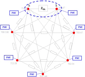
max. The reactive power injection level is adjusted by an agent of the MAS connected to a node of the communication network. Each agent is equipped with a bus voltage sensor that incorporates the PMU function (Figure 3.2) and with a memory buffer where it cyclically stores both the measured phasors and the corresponding measurement times for a predefined time interval equal to twait.Figure 3.2 Agents (red dotted) of the equivalent reduced network equipped with a bus voltage sensor that incorporates the PMU function
The algorithm corresponds to the repeated execution of the following steps (indicated as a compensation cycle).
3.2.3.1
Measurement, information exchange and calculation of ΔQ
1. An agent, which we denote as agent h, is assumed to be activated by another agent that also provides its updated priority index ph as explained in the last steps.
2. Agent h randomly chooses a neighboring agent in the communication network, identified as agent k (by avoiding the agent that has activated him, if there is another one available). 3. Agent h sends to agent k both the most updated values (present in the memory buffer) of
h
V
andθ
h of the positive sequence voltage phasor of the bus to which its compensator is connected and the indication of corresponding measurement time tmeas. Moreover it sendsthe identifier of bus h, value ph equal to its priority index and the values of the margins
between the current reactive output Qh of its compensator and the relevant minimum and
maximum limits, i.e. max
,max h
Q
hQ
hδ
=
−
and min ,min hQ
hQ
hδ
=
−
. (Figure 3.3)Figure 3.3 Measurement, information exchange from node h to node k – step 3
4. When agent k receives the information from agent h, it accepts the assignment only if ph is
not lower than its priority index, otherwise it denies the assignment by sending the relevant message to agent h that concludes the compensation process with priority ph.
5. If agent k accepts the assignment, it updates its priority index, if necessary, and it finds the bus voltage phasor Vk measured at tmeas stored in his memory buffer. It calculates
Q
'
hkand
Q
''
hk, by using (3.16) and (3.17). Moreover, analogously to agent h, it calculatesreactive power margins max
k
δ
and mink
δ
relevant to its compensator connected to bus k.6. In order to define adjustment
∆
Q
of the compensator set point, agent k compares the valueQ
hk=
min(
Q
'
hk,
Q
''
hk) sgn(
⋅
Q
'
hk)
with the maximum allowed variations of the reactive output of both compensators, i.e., maxk
δ
, min kδ
and max hδ
, min hδ
:(
)
(
max min min max)
max min hk, k , h , k , h
Q Q
δ
δ
δ
δ
∆ = − − (3.18)
If
Q
'
hk andQ
''
hk have different signs, then∆
Q
is set equal to 0.3.2.3.2
Implementation of ΔQ
7. Agent k changes the output of its compensator by adding
∆
Q
only if at least one of the following two conditions is met:max min
0 and
0 and
k kQ
V
V
Q
V
V
∆ >
<
∆ <
>
(3.19)where Vmax and Vmin are two values a few percent higher and lower than bus voltage rated
value, respectively, so to define the voltage interval of the normal operating state. If none of (3.19) is met, the reactive power output is not changed.
9. If agent h does not receive the message from agent k before twait after tmeas, it randomly
selects another agent k (step 2). Priority index ph remains unchanged.
10. If agent h receive the message from agent k, it changes the reactive output reference of its compensator by subtracting
∆
Q
only if at least one of the following two conditions is met:max min
0 and
0 and
h hQ
V
V
Q
V
V
∆ <
<
∆ >
>
(3.20)Figure 3.4 Measurement, information exchange, calculation and injection of ΔQ
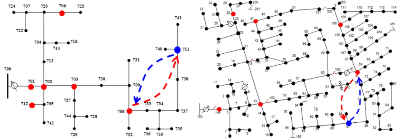
Figure 3.5 Correspondent example of bi-directional information exchange in the IEEE 37 and 123 node test feeders
3.2.3.3
Selection of the new couple of agents
11.Agent h randomly choses another agent to be activated as new agent h. (Figure 3.6)
12. When the chosen agent receives the relevant message from agent h with the priority ph, it
checks whether ph is greater or lower than its priority index. If it is equal or greater, the
receiving agent becomes the new agent h. If necessary,it updates its priority index to ph
returns in the idle state. If ph is lower than the priority index of the receiving agent, it
denies the assignment by sending the relevant message to agent h that concludes the compensation process with priority ph.
13. The new agent h starts again the procedure from step 1, waiting at least twait after tmeas so to
allow the stabilization of both compensators in the new operating conditions.
14. If old agent h does not receive the acknowledgment message from the new one by twait
after tmeas, it increments its priority index ph and randomly selects another agent to be
activated (step 11).
Figure 3.6 Selection of the new couple of agents
Conditions (3.19) and (3.20) exploits the fact that the connection to the transmission network through the substation guarantees the reactive power balance in the feeder.
3.3
Extended simulation platform
As already mentioned in Chapter 2, the developed platform is based on the interface between the communication simulator Riverbed-OPNET v18.0 [22] and the power system simulation environment EMTP-rv [23].
3.3.1
Communication model
A client-server communication model has been implemented for each OPNET-EMTP interface between a node of the communication network and the relevant agent that regulates a reactive power compensator implemented in the EMTP-rv model.
As illustrated in Figure 3.3, both the TCP and UDP node models are extended by an Esys module that as already explained in section 2.3 enables the management and the delivery of the communication packets. Each agent model in OPNET is composed by a client and a server in order to establish a point-to-point communication link.
a) b)
Figure 3.7. a) TCP and b) UDP extended node models. hub_rx and hub_tx: physical layer; mac (Media Access Control) and arp (Address Resolution Protocol): link layer; ip (Internet Protocol) and ip_encap (which encapsulates packets into IP datagrams): internet layer; tcp or udp and transport_interface: transport
layer.
A message generated by the EMTP-rv model of the agents, implemented by using a specific DLL, is transferred at first to the socket communication and then to the relevant Esys interface of the client in the OPNET agent model. The message is built into the TCP or UDP datagram and sent to the server of the destination agent through the communication network. The destination server processes the received datagram, extrapolates the information from the payload, and returns the message to the associated EMTP-rv interface.
The TCP model establishes a connection-oriented point-to-point communication link and includes connection set-up, data exchange, acknowledgment, retransmission, and connection termination functionalities. In the UDP model, the communication is connectionless, i.e. a message is sent from one end-point to another without prior arrangement or control. In our application, the dimension of TCP packets is 408 bits for data exchange and 376 bits for set-up, acknowledgment and connection termination. The dimension of UDP packets is 312 bits.
In OPNET, each agent node is connected to an IP-based gateways and a background data traffic generator. As illustrated in Figure 3.4 the IP-based gateways are connected to each other by a communication network with 64 kilobits per second (kbps) serial twisted-pair links and characterized by topology that follows the same tree configuration of the power distribution feeder. Each agent node is connected to the own router via a 10BaseT Ethernet link.
Figure 3.8 Correspondent Internet based communication network of the IEEE 37 node Test Feeder
The background traffic (BT) in the communication links is represented by an IP layer traffic flow from each node towards the router located at the substation. Each communication link is also characterized by a packet discard ratio (PDR), representing the probability of a packet to be lost in the link.
3.3.2
Power distribution feeder model
The EMTP-rv model of the network is mainly composed by the three-phase constant-parameters PI models for the representation of the unbalanced lines a three-phase OLTC transformer model at the substation fed by a positive sequence constant voltage generator (Figure 3.5), the models of reactive power compensator, loads and other cascaded OLTC transformers.. As EMTP-rv converts all the load models in RLC branches in time domain simulat