Integrated Pollution Prevention and Control
Reference Document on
Best Available Techniques on
Emissions from Storage
July 2006
This document is one of a series of foreseen documents as below (at the time of writing, not all documents have been drafted):
Reference Document on Best Available Techniques... Code
Large Combustion Plants LCP
Mineral Oil and Gas Refineries REF
Production of Iron and Steel I&S Ferrous Metals Processing Industry FMP
Non Ferrous Metals Industries NFM
Smitheries and Foundries Industry SF Surface Treatment of Metals and Plastics STM Cement and Lime Manufacturing Industries CL
Glass Manufacturing Industry GLS
Ceramic Manufacturing Industry CER
Large Volume Organic Chemical Industry LVOC Manufacture of Organic Fine Chemicals OFC
Production of Polymers POL
Chlor – Alkali Manufacturing Industry CAK Large Volume Inorganic Chemicals - Ammonia, Acids and Fertilisers Industries LVIC-AAF Large Volume Inorganic Chemicals - Solid and Others industry LVIC-S Production of Speciality Inorganic Chemicals SIC Common Waste Water and Waste Gas Treatment/Management Systems in the Chemical Sector CWW
Waste Treatments Industries WT
Waste Incineration WI
Management of Tailings and Waste-Rock in Mining Activities MTWR
Pulp and Paper Industry PP
Textiles Industry TXT
Tanning of Hides and Skins TAN
Slaughterhouses and Animals By-products Industries SA
Food, Drink and Milk Industries FDM
Intensive Rearing of Poultry and Pigs ILF Surface Treatment Using Organic Solvents STS
Industrial Cooling Systems CV
Emissions from Storage ESB
Reference Document...
General Principles of Monitoring MON Economics and Cross-Media Effects ECM
EXECUTIVE SUMMARY
The horizontal BAT (Best Available Techniques) Reference Document (BREF), entitled ‘Emissions from storage’ reflects an information exchange carried out under Article 16(2) of Council Directive 96/61/EC (IPPC Directive). This executive summary – which is intended to be read in conjunction with the BREF preface’s explanation of objectives, usage and legal terms – describes the main findings, a summary of the principal BAT conclusions and the associated emission/consumption levels. It can be read and understood as a stand alone document but, as a summary, it does not present all the complexities of the full BREF text. It is therefore not intended as a substitute for the full BREF text as a tool in BAT decision making.
Scope
The issue ‘emissions from storage of bulk or dangerous materials’ has been identified as a horizontal issue for all activities described in Annex I of the IPPC Directive. It means that this document covers the storage, transfer and handling of liquids, liquefied gases and solids, regardless of the sector or industry. It addresses emissions to air, soil and water, however, most attention is given to emissions to air. Information about air emissions from the storage and handling/transfer of solids focuses on dust.
General information, substances and classifications
Chapter 1, General information, provides general information on the environmental relevance of storage and handling of bulk and dangerous substances and the emission situation at storage installations by identifying, in general, the most important sources of emission to air and water and waste. Chapter 2, Substances and classifications, addresses the different classification systems of substances and the different categories of substances such as toxicity, flammability and harmfulness for the environment. For solids in bulk, it also addresses the dispersiveness class.
Applied storage, transfer and handling techniques, and techniques to be considered in the determination of BAT
Chapter 3, Applied storage, transfer and handling techniques, describes the techniques applied in the storage, transfer and handling of liquids, liquefied gases and solids. Chapter 4 describes techniques to be considered in the determination of BAT, again related to liquids, liquefied gases and solids. First, the liquids and liquefied gases related topics will be summarised, followed by the solids related topics.
Liquids and liquefied gases
For the storage of liquids and liquefied gases, the following modes are described in Chapter 3: • open top storage tanks
• external floating roof tanks • (vertical) fixed roof tanks
• aboveground horizontal storage tanks (atmospheric) • horizontal storage tanks (pressurised)
• vertical storage tanks (pressurised) • spheres (pressurised)
• mounded storage (pressurised)
• lifter roof (variable vapour space) tanks • refrigerated storage tanks
• underground horizontal storage tanks • containers and the storage of containers • basins and lagoons
• mined caverns (atmospheric) • mined caverns (pressurised) • salt leached caverns, and • floating storage.
Equipment such as vents; gauging, sample and access hatches; still wells and guide poles; drains; sealing elements and valves, and common issues are addresssed for tanks and other storage modes, together with issues such as design, commissioning and decommissioning, economics, management and operation are also addressed.
For the transfer and handling of liquids and liquefied gases equipment, such as vents, drains, sealing elements and pressure relief devices and the following techniques or operations are described:
• aboveground open and closed piping transfer systems • underground piping transfer systems
• loading and unloading of transporters • gravity flow
• pumps and compressors • inert gases
• flanges and gaskets, and • valves and fittings.
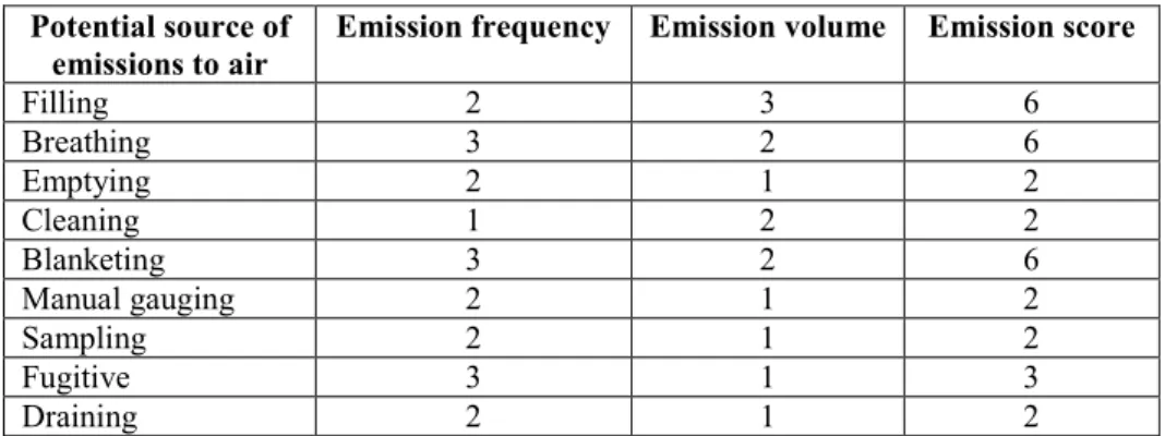
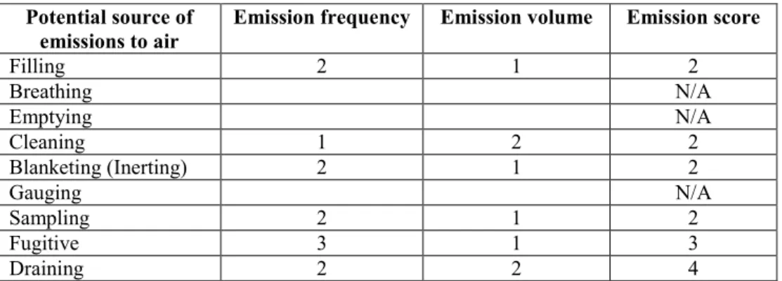
For each storage mode and for each transfer and handling operation, the relevant operational activities, such as filling, emptying, breathing, cleaning, draining, pigging, purging, connecting/disconnecting, and possible events/incidents, such as overfill and leakages, which potentially result in an emission, are listed. This forms the basis for describing the possible emissions by mode and activity. In particular, the potential emission sources from storage modes and transfer and handling operations, are selected for further analyses using a risk matrix approach. In this approach a scoring system is applied, calculating emission scores from operational sources by multiplying emission frequency by emission volume for each single storage mode and transfer and handling operation. All potential emission sources with a score of 3 or more are considered relevant and therefore emission control measures, further called ECM, to prevent or reduce the potential emissions from these sources are discussed in Chapter 4, Techniques to be considered in the determination of BAT.
Chapter 4 provides information on the possible ECM for each storage mode discussed in Chapter 3, which includes an assessment of relevant safety, operational aspects and economic considerations. Tanks are used for the storage of a wide range of substances, such as manure,
cooling water, and all sorts of chemicals and petrochemicals. In the petrochemical industry, where large volumes of chemical and oil products are stored in tanks, a lot of experience has been gained on preventing and reducing emissions and, therefore, an important part of the information in this BREF is related to the storage of petrochemical products in tanks.
In respect of emissions from the normal operation of a tank, the following ECM, which are not solely techniques, but also operation and management tools, are discussed and assessed:
• tank design
• inspection, maintenance and monitoring • emissions minimisation principle • floating, flexible and fixed covers • domes
• tank colour • solar shields • natural tank cooling
• external and internal floating roofs and the roof seals • pressure and vacuum relief valves
• draining systems
• vapour balancing and treatment, and • mixing and sludge removal.
This chapter also provides a general methodology tool for assessing the ECM for tanks for specific cases (specific product, location and storage tank) and provides a number of case studies.
ECM for potential emissions from tanks due to incidents and (major) accidents that are discussed and assessed are:
• safety and risk management • operational procedures and training
• low level indicator in external floating roof tanks • leakage and overfill, e.g.:
o leakage due to corrosion and erosion
o instrumentation and automation to prevent overfill and detect leakage
o impervious barriers and tank bunds
o double wall tanks
• fire protection, fire-fighting equipment and containment.
The storage techniques described in Chapter 3 for packaged dangerous materials are storage cells, storage buildings and storage yards. Operational emissions from packaged materials do not occur; the only possible emissions are from incidents and (major) accidents and ECM discussed and assessed in Chapter 4 are:
• safety and risk management • construction and ventilation • segregation and separation policies
• containment of leakage and contaminated extinguishant, and • fire protection and fire-fighting equipment.
In industry, basins and lagoons are most commonly used to hold cooling water, fire-fighting water and treated and untreated waste water. In agriculture, they are widely used for storing manure. ECM discussed and assessed in Chapter 4 for basins and lagoons are floating and plastic or rigid covers, impervious barriers and protection for overfill due to rainfall.
The types of caverns identified are mined caverns that can be atmospheric, but more often than not are pressurised, and salt leached caverns. Caverns are typically used for the storage of hydrocarbons, such as crude oil, gasoline, diesel fuel, fuel oil and liquefied petroleum gas (LPG). Emissions from normal operations of pressurised mined caverns and from salt leached caverns are considered as not significant and ECM are, therefore, not identified. However, for atmospheric mined caverns, vapour balancing is discussed and assessed as an ECM for emissions from normal operation. ECM for emissions from incidents and (major) accidents that are discussed for the different types of caverns, where appropriate, are:
• safety and risk management • monitoring
• intrinsic safety properties • maintaining hydrostatic pressure • cement injection
• interlock-system, and
• automated overfill protection.
Floating storage, i.e. ships, are sometimes used to provide additional, temporary storage capacity at a marine terminal. These ships are normally ex-trading vessels. Pressure and vacuum relief valves; tank colour; and vapour balancing, collection or treatment are similar to ECM identified for storage tanks. Some ECM for emissions from incidents and (major) accidents are identified, however, further information on these has not been submitted.
For the transfer and handling of liquids and liquefied gases, compared to the storage of these substances, far less ECM are identified and discussed, and the most important are: some management tools, prevention of internal and external corrosion and vapour balancing, and treatment for loading (and unloading) of transporters. For product handling, high performance valve and pump types, such as bellows valves and valves with a diaphragm and seal-less pumps and dual pressurised or unpressurised seals for pumps, are discussed and assessed.
Solids
Chapter 3 also describes the techniques applied in the storage, transfer and handling of solids in bulk. Different types of open storage, which is an important potential source of dust emissions, are described, and so is storage in sacks and bulk bags, silos and bunkers, and packaged dangerous solids. The actual handling of solid bulk material is another, and compared to storage an even greater potential source of dust emissions, and several loading, unloading and conveying techniques are described, and they are:
• grabs
• discharge hoppers • tubs
• suction air conveyors • mobile loading devices • dump pits
• fill pipes and tubes • cascade tubes • chutes • thrower belts • belt conveyors • bucket elevator
• chain and screw conveyors • pressure air conveyors, and • feeders.
Chapter 4, Techniques to be considered in the determination of BAT, describes ECM, and their assessment, for preventing dust emissions from the storage, transfer and handling of solids. The three dust preventing approaches that are identified to minimise dust from storage and handling are: pre-primary approaches, primary approaches and secondary approaches. Pre-primary approaches are part of the production or extraction process and, therefore, outside the scope of this document. Primary approaches are approaches to prevent dust formation and they can be divided into organisational, technical and constructional approaches, of which the latter one is only applicable to storage and not to handling. Secondary approaches are abatement techniques to limit the distribution of dust where the formation of dust could not be prevented. For the storage of solids, the approaches and techniques to prevent and limit dust emissions are listed in Table 1.
Approaches and techniques to reduce dust emissions from the storage of solids • monitoring
• layout and operation of storage places (by planning and operating personnel) • maintenance (of prevention/reduction techniques)
O rg an is at io na l
• reduction of wind attack areas • large volume silos
• sheds or roofs • domes
• self-erecting covers • silos and hoppers
C on st ru ct io na l
• wind protection mounds, fences and/or plantings • use of wind protection
• covering of open storage
P ri m ar y T ec hn ic al
• moistening of open storage
• water spraying/water curtains and jet spraying
S
ec
on
da
ry
• extraction of storage sheds and silos
Table 1: Approaches and techniques to reduce dust emissions from the storage of solids
All these techniques are described and assessed in Chapter 4. For the handling of solids, the approaches and techniques to prevent and limit dust emissions are listed in Table 2. These techniques are also described and assessed in Chapter 4.
Approaches and techniques to reduce dust emission from the transfer and handling of solids
Weather conditions
Measures (for the crane operator) when using a grab:
• reduction of the drop height when the material is discharged • total closing of the grab/jaws after material pick-up
• leaving the grab in the hoppers for a sufficient time after discharge • stopping of grab operations when the wind is strong.
Measures (for the operator) when using a belt conveyor: • suitable conveyor speed
• avoiding loading the belt up to its edges.
Measures (for the operator) when using a mechanical shovel: • reducing the drop height when the material is discharged • choosing the right position during discharging into a truck.
O rg an is at io na l
Layout and operation of storage sites (by the planner and the operating personnel) • reduction of transport distances
• adjusting the speed of vehicles • roads with hard surfaces • reduction of wind attack areas Optimised grabs
Use of closed conveyors (e.g. tube belt conveyors, screw conveyors) Conveyor belt without support pulleys
Primary measures on conventional conveyor belts Primary measures on transfer chutes
Minimising speed of descent
Minimisation of free fall heights (e.g. cascade hoppers) Use of dust barriers on dump pits and hoppers
Low dust bunker
P ri m ar y T ec hn ic al
Chassis of vehicles with round tops Screens for open conveyor belts
Housing or covering of the emission sources Applying covers, aprons or cones on fill tubes Extraction systems
Filter systems for pneumatic conveyors
Dump pits with suction equipment, housing and dust barriers Optimised discharge hoppers (in ports)
The techniques of water spraying/water curtains and jet spraying Cleaning conveyor belts
Fitting trucks with mechanical/hydraulic flaps Cleaning of roads S ec on da ry
Cleaning of vehicle tyres
Table 2: Approaches and techniques to reduce dust emission from transfer and handling of solids Best available techniques
The following paragraphs summarise Chapter 5, Best available techniques, by describing the techniques, approaches or activities from which conclusions on BAT are achieved. These relate to the most relevant environmental issues, namely emissions from normal operation to air and soil on the storage and handling of liquids and dust emissions from the storage and handling of solids. In some situations BAT conclusions on emissions from incidents and (major) accidents are also reported. These paragraphs should not be read instead of the ‘Best available techniques’ chapter. Evenso, the BAT chapter should not be read in isolation from the rest of the BREF, and for this reason cross references are made in each BAT conclusion to the relevant sections in other chapters.
The BAT conclusions in Chapter 5 are grouped as follows. Firstly, BAT conclusions are listed on the storage of liquids and liquefied gases, addressing the general principles to prevent and reduce emissions, which are:
• inspection and maintenance • location and layout
• tank colour
• emission minimisation principle in tank storage • monitoring of VOC, and
• dedicated systems.
This is followed by tank specific BAT conclusions on emissions from normal operation, addressing all the types of tanks that are described in Chapter 4, logically followed with BAT conclusions on (potential) emissions that do not result from normal tank operations, namely on the prevention of incidents and (major) accidents, addressing:
• safety and risk management • operational procedures and training • leakage due to corrosion and/or erosion
• operational procedures and instrumentation to prevent overfill • instrumentation and automation to detect leakage
• risk-based approach to emissions to soil below tanks • soil protection around tanks (containment)
• flammable areas and ignition sources • fire protection
• fire-fighting equipment, and
• containment of contaminated extinguishant.
The BAT conclusions on tank storage are followed by the BAT conclusions on the other storage techniques, namely:
• storage of packaged dangerous substances • basins and lagoons, and
• mined and salt leached caverns.
It is concluded that floating storage is not BAT.
Secondly, BAT conclusions on the transfer and handling of liquids and liquefied gases are listed, also starting with the general principles to prevent and reduce emissions, which in this case are:
• inspection and maintenance
• leak detection and repair programme
• emissions minimisation principle in tank storage • safety and risk management, and
• operational procedures and training.
BAT conclusions on specific techniques are achieved on piping systems addressing aboveground and underground piping systems, on abatement of emissions from loading and unloading activities, on the joints in the piping systems and the prevention of corrosion, on valves, on pumps and compressors, and on sampling connections.
Thirdly, BAT conclusions on dust emissions from open and enclosed storage and the storage of packaged materials are listed, ending with a BAT conclusion on safety and risk management.
Finally the BAT conclusions on dust emissions from the transfer and handling of solids are listed, starting with conclusions on the following general approaches to minimise dust emissions:
• scheduling the transfer activities • continuous transport
• reduction measures when applying discontinuous transport, which are:
o cleaning of roads and vehicle tyres
o moistening of the product
o minimising the speed of descent, and
o minimising the free fall height.
The BAT conclusions on general approaches are followed by conclusions on minimising dust emissions from the transfer techniques grabs and conveyors.
Concluding Remarks
In Chapter 7 – Concluding Remarks – the reader will find information on:
• which pieces of information were submitted by the TWG are the cornerstones of this BREF • the level of consensus reached on the BAT conclusions
• the recommendations for future work, and • the topics suggested for future R&D projects.
It is concluded that a high level of consensus was reached, because on the total of 110 BAT conclusions 5 split views were reported. These split views are regarding some BAT conclusions in the sections on storage and handling of liquids and liquefied gases. On the BAT conclusions regarding the storage and handling of solids, no split views were reported. The split views are on the following topics:
• the assessment methodology (ECM methodology)
• the requirement of applying a vapour treatment installation for the storage of certain volatile substances regarding three different tank types, and
• the tool that can be used for quantifying VOC emissions.
At the Information Exchange Forum (IEF) meeting in December 2004, a general split view from a few Member States on the emphasis on determining BAT on a case by case basis was recorded and added to Chapter 5.
Recommendations for the future review of the BREF address the following topics: • the development of a European classification system for air pollutants
• the separation of the storage and handling of liquids and liquefied gases and the storage and handling of solids which are two completely different areas and, therefore, require different expertise
• the monitoring of VOC emissions and tools to validate the emission calculation methods • updating the list of techniques to prevent or reduce emissions from tanks to the soil
• collecting data on the loading and unloading of transporters concerning volatile substances, and
• collecting feedback on the assessment methodology.
The EC is launching and supporting, through its RTD programmes, a series of projects dealing with clean technologies, emerging effluent treatment and recycling technologies and management strategies. Potentially these projects could provide a useful contribution to future BREF reviews. Readers are, therefore, invited to inform the EIPPCB of any research results which are relevant to the scope of this document (see also the preface of this document).
PREFACE
1. Status of this document
Unless otherwise stated, references to “the Directive” in this document means the Council Directive 96/61/EC on integrated pollution prevention and control. As the Directive applies without prejudice to Community provisions on health and safety at the workplace, so does this document.
This document forms part of a series presenting the results of an exchange of information between EU Member States and industries concerned on best available technique (BAT), associated monitoring, and developments in them. It is published by the European Commission pursuant to Article 16(2) of the Directive, and must therefore be taken into account in accordance with Annex IV of the Directive when determining “best available techniques”. 2. Relevant legal obligations of the IPPC Directive and the definition of BAT
In order to help the reader understand the legal context in which this document has been drafted, some of the most relevant provisions of the IPPC Directive, including the definition of the term ‘best available techniques’, are described in this preface. This description is inevitably incomplete and is given for information only. It has no legal value and does not in any way alter or prejudice the actual provisions of the Directive.
The purpose of the Directive is to achieve integrated prevention and control of pollution arising from the activities listed in its Annex I, leading to a high level of protection of the environment as a whole. The legal basis of the Directive relates to environmental protection. Its implementation should also take account of other Community objectives such as the competitiveness of the Community’s industry thereby contributing to sustainable development. More specifically, it provides for a permitting system for certain categories of industrial installations requiring both operators and regulators to take an integrated, overall look at the polluting and consuming potential of the installation. The overall aim of such an integrated approach must be to improve the management and control of industrial processes so as to ensure a high level of protection for the environment as a whole. Central to this approach is the general principle given in Article 3 that operators should take all appropriate preventative measures against pollution, in particular through the application of best available techniques enabling them to improve their environmental performance.
The term ‘best available techniques’ is defined in Article 2(11) of the Directive as ‘the most effective and advanced stage in the development of activities and their methods of operation which indicate the practical suitability of particular techniques for providing in principle the basis for emission limit values designed to prevent and, where that is not practicable, generally to reduce emissions and the impact on the environment as a whole.’ Article 2(11) goes on to clarify further this definition as follows:
‘techniques’ includes both the technology used and the way in which the installation is designed, built, maintained, operated and decommissioned;
‘available’ techniques are those developed on a scale which allows implementation in the relevant industrial sector, under economically and technically viable conditions, taking into consideration the costs and advantages, whether or not the techniques are used or produced inside the Member State in question, as long as they are reasonably accessible to the operator; ‘best’ means most effective in achieving a high general level of protection of the environment as a whole.
Furthermore, Annex IV of the Directive contains a list of ‘considerations to be taken into account generally or in specific cases when determining best available techniques ... bearing in mind the likely costs and benefits of a measure and the principles of precaution and prevention’. These considerations include the information published by the Commission pursuant to Article 16(2).
Competent authorities responsible for issuing permits are required to take account of the general principles set out in Article 3 when determining the conditions of the permit. These conditions must include emission limit values, supplemented or replaced where appropriate by equivalent parameters or technical measures. According to Article 9(4) of the Directive, these emission limit values, equivalent parameters and technical measures must, without prejudice to compliance with environmental quality standards, be based on the best available techniques, without prescribing the use of any technique or specific technology, but taking into account the technical characteristics of the installation concerned, its geographical location and the local environmental conditions. In all circumstances, the conditions of the permit must include provisions on the minimisation of long-distance or transboundary pollution and must ensure a high level of protection for the environment as a whole.
Member States have the obligation, according to Article 11 of the Directive, to ensure that competent authorities follow or are informed of developments in best available techniques. 3. Objective of this Document
Article 16(2) of the Directive requires the Commission to organise ‘an exchange of information between Member States and the industries concerned on best available techniques, associated monitoring and developments in them’, and to publish the results of the exchange.
The purpose of the information exchange is given in recital 25 of the Directive, which states that ‘the development and exchange of information at Community level about best available techniques will help to redress the technological imbalances in the Community, will promote the worldwide dissemination of limit values and techniques used in the Community and will help the Member States in the efficient implementation of this Directive.’
The Commission (Environment DG) established an information exchange forum (IEF) to assist the work under Article 16(2) and a number of technical working groups have been established under the umbrella of the IEF. Both IEF and the technical working groups include representation from Member States and industry as required in Article 16(2).
The aim of this series of documents is to reflect accurately the exchange of information which has taken place as required by Article 16(2) and to provide reference information for the permitting authority to take into account when determining permit conditions. By providing relevant information concerning best available techniques, these documents should act as valuable tools to drive environmental performance.
4. Information Sources
This document represents a summary of information collected from a number of sources, including in particular the expertise of the groups established to assist the Commission in its work, and verified by the Commission services. All contributions are gratefully acknowledged. 5. How to understand and use this document
The information provided in this document is intended to be used as an input to the determination of BAT in specific cases. When determining BAT and setting BAT-based permit conditions, account should always be taken of the overall goal to achieve a high level of protection for the environment as a whole.
The rest of this section describes the type of information that is provided in each section of the document.
Chapter 1 provides information on the storage and handling of bulk and dangerous substances in general.
Chapter 2 addresses the relevant classification of substances, such as toxicity, flammability and harmfulness for the environment. For solids in bulk it also addresses the dispersiveness class. Chapter 3 describes the various modes used to store liquids and gases, as well as possible emissions resulting from storage and transfer facilities both above and below ground. For each storage and transfer category, relevant operational activities and possible events/incidents are listed. Emission scorecards are developed and show which emissions are relevant and which therefore are discussed in more detail in Chapter 4.
This chapter also describes the storage and handling of solids in bulk. Heaps of bulk material such as cereals and coals in the open air are a potential source of dust emissions. Different types of heaps are described. Because the actual handling of solid bulk material is another potential source of dust emissions, several loading, unloading and conveying techniques are described.
Chapter 4 provides basic information on the possible Emission Control Measures (the so-called ECM) which, for liquids and gases, includes an assessment of relevant safety and operational aspects and economic considerations. ECM for preventing dust emissions from the storage and handling of solids are also described and assessed, but this assessment is less comprehensive than for liquids and gases. This chapter also provides for a general methodology for making the appropriate assessment of ECM for specific cases (specific product, storage mode and site) and providing a number of case studies. The purpose is thus to provide a general methodology to be applied to the storage and handling of substances to assist in the determination of BAT-based permit conditions. It should be noted, however, that the methodology presented in Chapter 4 will not necessarily be appropriate for all installations.
Chapter 5 focuses on the selection and description of BAT. It should be stressed, however, that this document does not propose emission limit values. The determination of appropriate permit conditions will involve taking account of local, site-specific factors such as the technical characteristics of the installation concerned, its geographical location and the local environmental conditions. For existing installations, the economic and technical viability of upgrading them also needs to be taken into account. Even the single objective of ensuring a high level of protection for the environment as a whole will often involve making trade-off judgements between different types of environmental impact, and these judgements will often be influenced by local considerations.
Since the best available techniques change over time, this document will be reviewed and updated as appropriate. All comments and suggestions should be made to the European IPPC Bureau at the Institute for Prospective Technological Studies at the following address:
Edificio Expo, c/Inca Garcilaso, s/n, E-41092 Seville, Spain Telephone: +34 95 4488 284
Fax: +34 95 4488 426
e-mail: [email protected] Internet: http://eippcb.jrc.es
Best Available Techniques Reference Document on
Emissions from Storage
EXECUTIVE SUMMARY ... I PREFACE ... IX SCOPE... XXV
1. GENERAL INFORMATION ...1
1.1. Environmental relevance of storage...1
1.2. Emission situation at storage installations ...2
1.2.1. Emissions to air ...2
1.2.2. Emissions to water...3
1.2.3. Noise emissions ...3
1.2.4. Waste aspects...3
1.2.5. Incidents and (major) accidents ...3
2. SUBSTANCES AND CLASSIFICATION...5
2.1. Nature and classification of dangerous materials ...5
2.2. Classification of packaged substances ...6
2.3. Dispersiveness classes of solid bulk material ...6
2.4. How to use classification systems in this document ...7
3. APPLIED STORAGE, TRANSFER AND HANDLING TECHNIQUES...9
3.1. Storage of liquids and liquefied gases ...9
3.1.1. Open top storage tanks ...12
3.1.2. External floating roof tanks (EFRT)...14
3.1.3. (Vertical) fixed roof tanks (FRT) ...16
3.1.4. Aboveground horizontal storage tanks (atmospheric) ...19
3.1.5. Horizontal storage tanks (pressurised)...21
3.1.6. Vertical storage tanks (pressurised)...23
3.1.7. Spheres (pressurised)...25
3.1.8. Mounded storage (pressurised)...26
3.1.9. Variable vapour space tanks ...29
3.1.10. Refrigerated storage tanks ...30
3.1.11. Underground horizontal storage tanks...33
3.1.12. Considerations related to tanks...35
3.1.12.1. Economics ...35
3.1.12.2. Design and construction ...35
3.1.12.3. Commissioning...38
3.1.12.4. Management ...38
3.1.12.5. Operation ...38
3.1.12.6. Decommissioning and demolition ...39
3.1.12.7. Tank equipment ...39
3.1.12.7.1. Vents ...40
3.1.12.7.2. Gauging and sample hatches...41
3.1.12.7.3. Still wells and guide poles ...41
3.1.12.7.4. Instrumentation ...41 3.1.12.7.5. Access hatches ...42 3.1.12.7.6. Drains...42 3.1.12.7.7. Mixers ...43 3.1.12.7.8. Heating systems ...43 3.1.12.7.9. Sealing elements ...43 3.1.12.7.10. Valves ...44
3.1.13. Containers and the storage of containers ...44
3.1.13.1. Storage cells...46
3.1.13.2. Storage buildings ...46
3.1.13.3. Outside storage (storage yards)...47
3.1.14. Basins and lagoons ...48
3.1.15. Mined caverns (atmospheric) ...49
3.1.16. Mined caverns (pressurised) ...56
3.1.17. Salt leached caverns...58
3.2.1. Product transfer ... 64
3.2.1.1. Aboveground closed piping transfer systems... 64
3.2.1.2. Aboveground open piping transfer systems ... 65
3.2.1.3. Underground piping transfer systems... 67
3.2.1.4. Loading and unloading of transporters... 68
3.2.2. Product handling ... 70
3.2.2.1. Gravity flow ... 71
3.2.2.2. Pumps... 72
3.2.2.3. Compressors... 73
3.2.2.4. Inert gases ... 73
3.2.2.5. Flanges and gaskets... 74
3.2.2.6. Valves and fittings... 75
3.2.3. Considerations related to transfer and handling systems ... 76
3.2.3.1. Economics... 76
3.2.3.2. Design and construction ... 76
3.2.3.3. Commissioning and decommissioning... 78
3.2.4. Equipment and fittings ... 78
3.2.4.1. Sealing elements... 79
3.2.4.2. Vents, drains and sample points... 80
3.2.4.3. Instrumentation on piping systems... 80
3.2.4.4. Pressure relief devices... 81
3.2.5. Transfer and handling of packaged goods... 81
3.3. Storage of solids... 83
3.3.1. Open storage ... 83
3.3.2. Sacks and bulk bags ... 84
3.3.3. Silos and bunkers ... 85
3.3.4. Packaged dangerous solids... 85
3.4. Transfer and handling of solids... 86
3.4.1. The construction and reclaiming of heaps... 87
3.4.2. Loading and unloading devices... 88
3.4.2.1. General emission sources from transfer and handling... 88
3.4.2.2. Grabs ... 89
3.4.2.3. Discharge hoppers... 91
3.4.2.4. Tubs... 91
3.4.2.5. Suction air conveyors... 92
3.4.2.6. Mobile loading devices ... 93
3.4.2.7. Wagon and truck emptying ... 94
3.4.2.8. Dump pits... 95 3.4.2.9. Fill pipes... 96 3.4.2.10. Fill tubes... 96 3.4.2.11. Cascade tubes ... 97 3.4.2.12. Chutes ... 98 3.4.2.13. Thrower belts ... 99 3.4.2.14. Belt conveyors... 100 3.4.2.15. Bucket elevator... 104 3.4.2.16. Chain conveyors... 106
3.4.2.16.1. Trough chain conveyors ... 106
3.4.2.16.2. Scraper conveyors ... 107
3.4.2.17. Screw conveyors ... 107
3.4.2.18. Pressure air conveyors... 108
3.4.2.19. Feeders ... 109
3.4.3. Transfer and handling of packaged good ... 110
4. TECHNIQUES TO CONSIDER IN THE DETERMINATION OF BAT... 111
4.1. Storage of liquid and liquefied gas... 111
4.1.1. ECM assessment methodology for the storage of liquid and liquefied gas... 111
4.1.2. ECM for tanks – general ... 113
4.1.2.1. Tank design ... 113
4.1.2.2. Inspection, maintenance and monitoring... 114
4.1.2.2.1. Risk and Reliability Based Maintenance (RRM) ... 116
4.1.2.2.2. In-service and out-of-service inspections ... 117
4.1.2.2.4. Gas detection techniques...120
4.1.2.3. Location and layout ...120
4.1.3. ECM for tanks – operational – gas emissions...121
4.1.3.1. Emissions minimisation principle in tank storage ...121
4.1.3.2. Floating covers ...122
4.1.3.3. Flexible covers or tent covers ...123
4.1.3.4. Fixed/rigid covers ...124
4.1.3.5. Domes...124
4.1.3.6. Tank colour...126
4.1.3.7. Solar shields...127
4.1.3.8. Natural tank cooling ...128
4.1.3.9. Roof seals for external and internal floating roofs...128
4.1.3.9.1. Rim seals...128
4.1.3.9.2. Still wells and guide poles ...133
4.1.3.10. Internal floating roof (IFR) ...135
4.1.3.11. Pressure and vacuum relief valves (PVRV)...137
4.1.3.12. Closed drain systems ...138
4.1.3.13. Vapour balancing...139
4.1.3.14. Vapour holders – flexible diaphragm tanks ...140
4.1.3.15. Vapour treatment ...141 4.1.3.15.1. Thermal oxidation...144 4.1.3.15.2. Adsorption ...145 4.1.3.15.3. Absorption (‘washing’)...146 4.1.3.15.4. Condensation ...147 4.1.3.15.5. Membrane separation...148
4.1.3.16. Compatibility of ECM for gas emissions – operational...148
4.1.4. ECM for tanks – operational – liquid emissions...151
4.1.4.1. Manual draining...151
4.1.4.2. Semi-automatic tank drain valves...151
4.1.4.3. Fully automatic tank drain valves ...152
4.1.4.4. Dedicated systems ...153
4.1.5. ECM for tanks – waste ...153
4.1.5.1. Tank mixing...153
4.1.5.2. Sludge removal ...154
4.1.6. ECM for tanks – incidents and (major) accidents...155
4.1.6.1. Safety and risk management ...155
4.1.6.1.1. Operational procedures and training ...156
4.1.6.1.2. Low level indicator in EFRT ...157
4.1.6.1.3. Leakage and overfill ...157
4.1.6.1.4. Corrosion and erosion...158
4.1.6.1.5. Operational procedures and training to prevent overfill ...159
4.1.6.1.6. Instrumentation and automation to prevent overfill...159
4.1.6.1.7. Instrumentation and automation to detect leakage...160
4.1.6.1.8. Risk-based approach for emissions to soil below tanks...163
4.1.6.1.9. Double tank bottoms under aboveground tanks...165
4.1.6.1.10. Impervious barriers under aboveground tanks...166
4.1.6.1.11. Tank bunds and liner systems ...167
4.1.6.1.12. Laminated concrete containment under aboveground tanks ...168
4.1.6.1.13. Aboveground double wall tanks ...169
4.1.6.1.14. Cup-tanks...170
4.1.6.1.15. Aboveground double wall tank with monitored bottom discharge ...171
4.1.6.1.16. Underground double wall tanks ...172
4.1.6.1.17. Underground single wall tanks with secondary containment...172
4.1.6.2. Fire protection, fire-fighting equipment and containment ...173
4.1.6.2.1. Flammable areas and ignition sources ...173
4.1.6.2.2. Fire protection...174
4.1.6.2.3. Fire-fighting equipment ...174
4.1.6.2.4. Containment of contaminated extinguishant...174
4.1.7. ECM for storing containers – incidents and (major) accidents...175
4.1.7.1. Safety and risk management ...176
4.1.7.2. Construction and ventilation...176
4.1.7.3. Separation policy ...179
4.1.7.6. Fire protection and fire-fighting equipment ... 184
4.1.7.6.1. Preventing ignition ... 184
4.1.7.6.2. Fire-fighting systems... 186
4.1.8. ECM for basins and lagoons – operational – gas emissions ... 186
4.1.8.1. Floating covers ... 186
4.1.8.2. Plastic or rigid covers... 187
4.1.9. ECM for basins and lagoons – operational – emissions to soil and water ... 188
4.1.9.1. Impervious barriers ... 188
4.1.10. ECM for basins and lagoons – operational – waste ... 188
4.1.11. ECM for basins and lagoons – incidents and accidents ... 188
4.1.11.1. Protection for overfill due to rainfall... 188
4.1.12. ECM for mined caverns (atmospheric) – operational – gas emissions ... 188
4.1.12.1. Vapour balancing ... 188
4.1.13. ECM for mined caverns (atmospheric) – incidents and (major) accidents ... 189
4.1.13.1. Safety and risk management ... 189
4.1.13.2. Monitoring ... 189
4.1.13.3. Intrinsic safety properties ... 189
4.1.13.4. Blanketing ... 190
4.1.13.5. Maintaining hydrostatic pressure ... 191
4.1.13.6. Cement injection ... 191
4.1.13.7. Interlock-system... 192
4.1.13.8. Automated overfill protection ... 192
4.1.14. ECM for mined caverns (pressurised) – incidents and (major) accidents ... 192
4.1.14.1. Safety and risk management ... 192
4.1.14.2. Monitoring ... 192
4.1.14.3. Intrinsic safety properties ... 193
4.1.14.4. Fail-safe valves... 193
4.1.14.5. Maintaining hydrostatic pressure ... 193
4.1.14.6. Cement injection ... 193
4.1.14.7. Interlock-system... 193
4.1.14.8. Automated overfill protection ... 193
4.1.15. ECM for salt leached caverns – incidents and (major) accidents... 194
4.1.15.1. Safety and risk management ... 194
4.1.15.2. Monitoring ... 194
4.1.15.3. Intrinsic safety properties ... 194
4.1.16. ECM for floating storage – operational – gas emissions... 195
4.1.16.1. Pressure and vacuum relief valves (PVRV) ... 195
4.1.16.2. Tank colour ... 195
4.1.16.3. Vapour balancing, collection or treatment ... 195
4.1.17. ECM for floating storage – operational – emissions to water ... 195
4.1.18. ECM for floating storage – incidents and (major) accidents... 195
4.1.18.1. Safety and risk management ... 195
4.1.18.2. Inspection and maintenance of the hull... 195
4.1.18.3. Prevention of overfill ... 195
4.2. Transfer and handling of liquid and liquefied gas... 196
4.2.1. Management tools for transfer and handling... 196
4.2.1.1. Operational procedures and training ... 196
4.2.1.2. Inspection, maintenance and monitoring... 196
4.2.1.3. Leak detection and repair (LDAR) programme ... 196
4.2.1.4. Safety and risk management ... 196
4.2.2. ECM for aboveground closed piping – operational – gas emissions ... 197
4.2.2.1. Reduction in number of flanges and connectors ... 197
4.2.2.2. Selection and maintenance of gaskets ... 197
4.2.2.3. Improved flanges... 199
4.2.2.4. Vapour collection ... 200
4.2.3. ECM for aboveground closed piping – incidents and (major) accidents... 200
4.2.3.1. Internal corrosion and erosion... 200
4.2.3.2. External corrosion – aboveground piping ... 200
4.2.4. ECM for aboveground open piping – operational – gas emissions... 200
4.2.4.1. Replacement with closed piping systems ... 200
4.2.4.2. Reduced length... 201
4.2.6. ECM for underground closed piping – operational – gas emissions ...201
4.2.7. ECM for underground closed piping – incidents and (major) accidents ...201
4.2.7.1. External corrosion – underground piping ...202
4.2.8. ECM for the loading and unloading of transporters ...202
4.2.8.1. Vapour balancing for the loading and unloading of transporters...202
4.2.8.2. Vapour treatment for the loading of transporters...204
4.2.9. ECM for product handling systems – operational – gas emissions ...205
4.2.9.1. High quality equipment ...205
4.2.9.2. Elimination of open-ended lines and valves ...206
4.2.9.3. Bellows valves...206
4.2.9.4. Valves with a diaphragm ...206
4.2.9.5. Rotating control valves ...207
4.2.9.6. Variable speed pumps...207
4.2.9.7. Double walled valves...208
4.2.9.8. Pressure and thermal relief valves ...208
4.2.9.9. Seal-less pumps ...209
4.2.9.10. Improved single seals for pumps ...210
4.2.9.11. Dual unpressurised seals for pumps...211
4.2.9.12. Dual pressurised seals for pumps...211
4.2.9.13. Seals for compressors ...212
4.2.9.14. Improved sampling connections ...212
4.2.10. ECM for product handling systems – incidents and (major) accidents ...213
4.2.10.1. Flanged connections in liquid tight pits ...213
4.3. Storage of solids ...214
4.3.1. General – Emission Control Measures (ECM) ...214
4.3.2. General approaches to minimise dust from storage...214
4.3.3. Primary organisational approaches to minimise dust from storage ...215
4.3.3.1. Monitoring dust emissions from open storage...215
4.3.4. Primary constructional techniques to minimise dust from storage ...216
4.3.4.1. Large volume silos...216
4.3.4.2. Sheds or roofs ...217
4.3.4.3. Domes...218
4.3.4.4. Self-erecting covers ...218
4.3.4.5. Silos and hoppers...219
4.3.5. Dust prevention/reduction techniques and measures applied to open storage ...220
4.3.6. Primary techniques to minimise dust from storage...223
4.3.6.1. Spraying of water with or without additives...223
4.3.6.2. Wind protection methods...225
4.3.6.3. Tarpaulins or nets ...225
4.3.7. Secondary techniques to minimise dust from storage – dust filters on silos and hoppers ...226
4.3.8. Measures to prevent incidents and (major) accidents ...227
4.3.8.1. Safety and risk management ...227
4.3.8.2. Warehouse fires involving solid materials...227
4.3.8.3. Explosion resistant silos ...229
4.3.8.4. Relief vents ...229
4.3.9. Leaching to soil or surface water...230
4.4. Handling of solids...231
4.4.1. General – Emission Control Measures (ECM) ...231
4.4.2. General approaches to minimise dust from handling ...231
4.4.3. Primary organisational approaches to minimise dust from handling...234
4.4.3.1. Weather conditions ...234
4.4.3.2. Measures for the crane operator when using a grab...234
4.4.3.3. Measures (for the operator) when using a belt conveyor...235
4.4.3.4. Measures (for the operator) when using a mechanical shovel ...236
4.4.3.5. Layout and operation of storage sites (by the planner and the operating personnel) ...236
4.4.3.5.1. Reduction of discontinuous transport and transport distances ...236
4.4.3.5.2. Adjusting the speed of vehicles ...237
4.4.3.5.3. Roads with hard surfaces ...237
4.4.4. Primary constructional techniques to minimise dust from loading and unloading ...238
4.4.4.1. Loading and unloading in a closed building ...238
4.4.5.2. Closed conveyors ... 239
4.4.5.3. Conveyor belt without support pulleys ... 240
4.4.5.3.1. Aerobelt... 241
4.4.5.3.2. Low friction conveyor ... 241
4.4.5.3.3. Conveyor with diabolo ... 242
4.4.5.4. Primary measures on conventional conveyor belts ... 242
4.4.5.5. Primary measures on transfer chutes (e.g. on belt conveyors) ... 243
4.4.5.6. Minimising the speed of descent of the loaded material ... 244
4.4.5.7. Minimisation of free fall heights ... 244
4.4.5.8. Dump pits with dust barriers ... 244
4.4.5.9. Low dust bunker... 245
4.4.5.10. Chassis of vehicles with round tops ... 245
4.4.6. Secondary techniques to minimise dust from handling... 246
4.4.6.1. Screens for open conveyor belts... 246
4.4.6.2. Housing or covering of the emission source ... 246
4.4.6.3. Applying covers, aprons or cones on fill tubes ... 247
4.4.6.4. Extraction systems ... 247
4.4.6.5. Lamellae filters for pneumatic conveyors ... 248
4.4.6.6. Dump pits with suction equipment, housing and dust barriers... 249
4.4.6.7. Optimised discharge hoppers (in ports)... 250
4.4.6.8. The techniques of water spraying/water curtains ... 250
4.4.6.9. Jet spraying ... 251
4.4.6.10. Cleaning conveyor belts ... 252
4.4.6.11. Fitting trucks with mechanical/hydraulic flaps ... 253
4.4.6.12. Cleaning of roads ... 253
4.4.6.13. Cleaning of vehicle tyres... 254
4.4.7. Measures to prevent emissions from handling packaged good ... 255
4.4.8. Safety and risk management in handling solids ... 255
5. BEST AVAILABLE TECHNIQUES... 257
5.1. Storage of liquids and liquefied gases... 259
5.1.1. Tanks... 259
5.1.1.1. General principles to prevent and reduce emissions ... 259
5.1.1.2. Tank specific considerations ... 260
5.1.1.3. Preventing incidents and (major) accidents... 264
5.1.2. Storage of packaged dangerous substances... 267
5.1.3. Basins and lagoons... 268
5.1.4. Atmospheric mined caverns... 268
5.1.5. Pressurised mined caverns ... 269
5.1.6. Salt leached caverns ... 270
5.1.7. Floating storage... 270
5.2. Transfer and handling of liquids and liquefied gases ... 270
5.2.1. General principles to prevent and reduce emissions ... 270
5.2.2. Considerations on transfer and handling techniques... 271
5.2.2.1. Piping ... 271
5.2.2.2. Vapour treatment... 271
5.2.2.3. Valves... 272
5.2.2.4. Pumps and compressors ... 272
5.2.2.5. Sampling connections ... 273
5.3. Storage of solids... 274
5.3.1. Open storage ... 274
5.3.2. Enclosed storage ... 274
5.3.3. Storage of packaged dangerous solids ... 275
5.3.4. Preventing incidents and (major) accidents ... 275
5.4. Transfer and handling of solids... 275
5.4.1. General approaches to minimise dust from transfer and handling ... 275
5.4.2. Considerations on transfer techniques... 276
6. EMERGING TECHNIQUES ... 279
6.1. Handling of solids ... 279
6.1.1. Screw conveyor... 279
6.1.2. Low-dust dock transhipment containers without negative pressure extraction... 280
7. CONCLUDING REMARKS...283
7.1. Timing of the work ...283
7.2. Sources of information ...283
7.3. Degree of consensus reached...283
7.4. Recommendations for future work ...285
7.5. Suggested topics for future R & D projects ...286
REFERENCES ...287
GLOSSARY ...293
8. ANNEXES...299
8.1. International Codes...299
8.2. Dangerous substances and classification ...331
8.3. Compatibility of hazardous substances...359
8.4. Dispersiveness classes of solid bulk materials...360
8.5. Relevant solid bulk materials...366
8.6. Summary of MS requirements on underground tank storage modes and equipment for liquids ...368
8.7. Storage modes and relevant solid bulk materials...369
8.8. Handling techniques and relevant solid bulk material ...370
8.9. ECM Scorecards for storing liquid and liquefied gas - operational...372
8.10. ECM Scorecards for transfer and handling of liquid and liquefied gas ...385
8.11. Methodology for completion of the ECM Assessment Table...389
8.12. Gaseous and liquid emission control measure assessment matrix ...393
8.13. Case studies for ECM assessment methodology...394
8.13.1. Case study number 1; existing EFRT ...394
8.13.2. Case study number 2; new FRT...398
8.13.3. Case study number 2a; new FRT...401
8.13.4. Case study number 3; new FRT...403
8.13.5. Case study number 4; new FRT...406
8.14. ECM Scorecards for the storage of solids...412
8.15. ECM Scorecards for the handling of solids ...415
8.16. Characteristics of fire-fighting systems ...420
8.17. Distances for the storage of gas cylinders...422
8.18. Examples of applied distances for the storage of flammable liquid in tanks ...424
8.19. Typical checklist for the design of a product storage tank in a chemical plant facility ...426
8.20. Efficiency of an EFRT depending on the number of filling cycles per year and tank ...429
8.21. Efficiency of an EFRT depending on the turnover rate per year and tank diameter for crude oil and gasoline ...430
8.22. Efficiency of different types of floating roof seals ...431
8.23. Efficiency of an IFRT depending on the number of filling cycles per year and the tank diameter ...432
Table 1: Approaches and techniques to reduce dust emissions from the storage of solids ... v
Table 2: Approaches and techniques to reduce dust emission from transfer and handling of solids ... vi
Table 2.1: Categories of dangerous substance according to Directive 67/548/EEC ... 5
Table 3.1: Cross-references of storage modes for liquids and liquefied gases... 9
Table 3.2: Cross-references for open top tanks ... 13
Table 3.3: Possible emissions to air from ‘operational sources’ with open top storage tanks... 13
Table 3.4: Possible liquid emissions to water or waste from ‘operational sources’ with open top storage tanks ... 13
Table 3.5: Cross-references for EFRT ... 15
Table 3.6: Possible emissions to air from ‘operational sources’ with EFRT ... 16
Table 3.7: Possible liquid emissions to water or waste from ‘operational sources’ with EFRT ... 16
Table 3.8: Design ratings for the different types of fixed roof tanks... 18
Table 3.9: Cross-references for FRT... 18
Table 3.10: Possible emissions to air from ‘operational sources’ with FRT ... 18
Table 3.11: Possible liquid emissions to water or waste from ‘operational sources’ with FRT... 19
Table 3.12: Cross references for aboveground horizontal tanks ... 20
Table 3.13: Possible emissions to air from ‘operational sources’ with aboveground horizontal storage tanks ... 21
Table 3.14: Possible liquid emissions to water or waste from ‘operational sources’ with aboveground horizontal storage tanks... 21
Table 3.15: Cross-references for horizontal storage tanks (pressurised)... 22
Table 3.16: Possible emissions to air from ‘operational sources’ with horizontal storage tanks (pressurised) ... 23
Table 3.17: Possible liquid emissions to water or waste from ‘operational sources’ with horizontal storage tanks (pressurised)... 23
Table 3.18: Cross-references for relevant tank equipment and fitting for vertical storage tanks (pressurised) ... 24
Table 3.19: Possible emissions to air from ‘operational sources’ with vertical storage tanks (pressurised) ... 25
Table 3.20: Possible liquid emissions to water or waste from ‘operational sources’ with vertical storage tanks (pressurised)... 25
Table 3.21: Cross-references for spheres (pressurised)... 25
Table 3.22: Possible emissions to air from ‘operational sources’ with spheres (pressurised)... 26
Table 3.23: Possible liquid emissions to water or waste from ‘operational sources’ with spheres (pressurised) ... 26
Table 3.24: Cross-references for mounded storage ... 28
Table 3.25: Possible emissions to air from ‘operational sources’ with pressurised mounded storage ... 28
Table 3.26: Possible liquid emissions to water or waste from ‘operational sources’ with pressurised mounded storage ... 28
Table 3.27: Cross-references for lifter roof tanks ... 29
Table 3.28: Possible emissions to air from ‘operational sources’ with lifter roof tanks... 30
Table 3.29: Possible emissions to water or waste from ‘operational sources’ with lifter roof tanks... 30
Table 3.30: Cross-references for refrigerated storage tanks... 32
Table 3.31: Possible emissions to air from ‘operational sources’ with refrigerated storage ... 32
Table 3.32: Possible liquid emissions to water or waste from ‘operational sources’ with refrigerated storage ... 32
Table 3.33: Cross-references for underground horizontal storage tanks ... 34
Table 3.34: Possible emissions to air from ‘operational sources’ with underground horizontal storage ... 34
Table 3.35: Possible liquid emissions to water or waste from ‘operational sources’ with underground horizontal storage ... 34
Table 3.36: Cost elements for storage tanks... 35
Table 3.37: Possible emissions to air from ‘operational sources’ with basins and lagoons ... 49
Table 3.38: Possible emissions to water or waste from ‘operational sources’ with basins and lagoons .... 49
Table 3.39: Possible emissions to air from ‘operational sources’ with atmospheric mined caverns of the fixed waterbed type ... 55
Table 3.40: Possible emissions to air from ‘operational sources’ with atmospheric mined caverns of the fluctuating waterbed type ... 55
Table 3.41: Possible emissions to water or waste from ‘operational sources’ with mined caverns (atmospheric)... 55
Table 3.42: Possible emissions to air from ‘operational sources’ with mined caverns (pressurised) ...57 Table 3.43: Possible emissions to water or waste from ‘operational sources’ with mined caverns
(pressurised)...57 Table 3.44: Possible emissions to air from ‘operational sources’ with salt leached caverns ...60 Table 3.45: Possible emissions to water or waste from ‘operational sources’ with salt leached caverns ...60 Table 3.46: Cross references for floating storage ...61 Table 3.47: Possible emissions to air from ‘operational sources’ with floating storage ...61 Table 3.48: Possible emissions to water or waste from ‘operational sources’ with floating storage ...61 Table 3.49: Cross-references of transfer and handling modes for liquids and liquefied gases ...62 Table 3.50: Possible emissions to air from ‘operational sources’ with aboveground closed piping transfer
systems...65 Table 3.51: Possible liquid emissions to soil/groundwater from ‘operational sources’ with aboveground
closed piping transfer systems ...65 Table 3.52: Possible emissions to air from ‘operational sources’ with aboveground open piping transfer
systems...66 Table 3.53: Possible liquid emissions to soil/groundwater from ‘operational sources’ with aboveground
open piping transfer systems...66 Table 3.54: Possible emissions to air from ‘operational sources’ with underground closed piping transfer
systems...67 Table 3.55: Possible liquid emissions to soil/groundwater from ‘operational sources’ with underground
piping transfer systems ...68 Table 3.56: Possible emissions to air from ‘operational sources’ with flexible hoses or loading arms ...70 Table 3.57: Possible liquid emissions to soil/groundwater from ‘operational sources’ with flexible hoses
or loading arms ...70 Table 3.58: Possible emissions to air from ‘operational sources’ with product handling...71 Table 3.59: Possible liquid emissions to soil/groundwater from ‘operational sources’ with product
handling ...72 Table 3.60: Average emissions from seals in process pumps when handling mineral oils...79 Table 3.61: Possible emissions to air from ‘operational sources’ with transfer and handling of packaged
goods...81 Table 3.62: Possible liquid emissions to soil/groundwater from ‘operational sources’ with transfer and
handling of packaged goods...82 Table 3.63: Storage modes for solids and reference to the sections ...83 Table 3.64: Criteria for the selection of longitudinal and ring-shaped storage places ...84 Table 3.65: Techniques for the transfer and handling of solids, with section references ...86 Table 3.66: Typical techniques to construct a heap ...87 Table 3.67: Survey of typical wagons/trucks for bulk materials...94 Table 4.1: Paint factors ...126 Table 4.2: Heat radiant reflectance of different tank colours...126 Table 4.3: Emission Control Technologies – applicability limitations and normalised costs as given in the CWW BREF ...142 Table 4.4: Substances treated in a vapour treatment installation ...144 Table 4.5: ECM compatibility ...149 Table 4.6: Possible ECM by storage mode...150 Table 4.7: Scoring system to identify the risk level of emissions to soil ...164 Table 4.8: Definition of zones ...173 Table 4.9: Main potential events concerning the storage of packaged dangerous materials...175 Table 4.10: Minimum separation distances of an outdoor storage with flammable liquid ...179 Table 4.11: Minimum separation distances of an outdoor storage with hazardous substances ...181 Table 4.12: Approaches and techniques to reduce dust emission from storage and cross-reference...215 Table 4.13: Dust reduction approaches to open storage and their limitations ...222 Table 4.14: Materials involved in the 290 fires ...228 Table 4.15: Ignition sources...228 Table 4.16: Approaches and techniques to reduce dust emissions from loading and unloading ...233 Table 4.17: Comparison of different closed belt conveyors ...239 Table 4.18: Emission reduction in bunker number 3 and 4 ...245 Table 4.19: Efficiency of various sweepers ...254 Table 8.1: Assignment of the industrial activities according to Annex I of the IPPC Directive to the
relevant solid bulk materials ...367 Table 8.2: Summary of MS requirements on underground tanks ...368 Table 8.3: Storage modes and relevant bulk materials ...369 Table 8.4: Loading and unloading techniques and relevant bulk materials ...370 Table 8.5: ECM-cards operational emissions; Aboveground Open Top Tank ...372
Tank ... 373 Table 8.7: ECM-cards operational emissions; Aboveground Atmospheric Storage: Fixed Roof Tank... 374 Table 8.8: ECM-cards operational emissions; Aboveground Atmospheric Storage: Horizontal Storage
Tank ... 375 Table 8.9: ECM-cards operational emissions; Aboveground Pressurised Storage: Spheres... 376 Table 8.10: ECM-cards operational emissions; Aboveground Pressurised Storage: Horizontal Storage
Tank ... 377 Table 8.11: ECM-cards operational emissions; Aboveground Refrigerated Storage... 378 Table 8.12: ECM-cards operational emissions; Underground Tank ... 379 Table 8.13: ECM-cards operational emissions; Atmospheric Cavern... 380 Table 8.14: ECM-cards operational emissions; Atmospheric Salt Dome ... 381 Table 8.15: ECM-cards operational emissions; Pressurised Cavern ... 381 Table 8.16: ECM-cards operational emissions; Lagoon and Basin... 382 Table 8.17: ECM-cards operational emissions; Floating Storage ... 383 Table 8.18: ECM-cards operational emissions; Lifter Roof Tank ... 384 Table 8.19: ECM-cards operational emissions; Aboveground Transfer Systems: Closed Piping... 385 Table 8.20: ECM-cards operational emissions; Aboveground Transfer Systems: Open Piping ... 386 Table 8.21: ECM-cards operational emissions; Underground Transfer Systems: Closed Piping ... 387 Table 8.22: ECM-cards operational emissions; Product Handling Methods: Pumps & Compressor ... 388 Table 8.23: Case study number 1 – Initial ECM Assessment ... 409 Table 8.24: Case study number 1 – Second Round of ECM Assessment ... 409 Table 8.25: Case study number 2 – Initial ECM Assessment ... 410 Table 8.26: Case study number 2a – Initial ECM Assessment... 410 Table 8.27: Case study number 3 – Initial ECM Assessment ... 411 Table 8.28: Case study number 4 – Initial ECM Assessment ... 411 Table 8.29: ECM Scorecard for the storage of solids... 413 Table 8.30: ECM Scorecard on the handling of solids... 416 Table 8.31: Distances for closed storage of gas cylinders... 422 Table 8.32: Distances for open storage of gas cylinders ... 423 Table 8.33: Distances for the aboveground storage of K1, K2, K3and crude applied in the Netherlands 424 Table 8.34: Distances for the aboveground storage of flammable liquids in ‘large’ tanks applied in the UK ... 425
List of figures
Figure 3.1: Flow chart with potential emissions resulting from aboveground and underground storage facilities ...10 Figure 3.2: Risk matrix for emissions from storage of liquids and liquefied gases ...11 Figure 3.3: Example of an open top slurry tank with underground receiving pit ...12 Figure 3.4: Typical floating roof tank with pontoon floating roof...14 Figure 3.5: Typical floating roof tank with double-deck floating roof ...15 Figure 3.6: Vertical fixed roof tank with some emission control equipment installed ...17 Figure 3.7: Typical example of a fixed roof tank ...17 Figure 3.8: Aboveground horizontal tank with some emission control equipment installed ...20 Figure 3.9: Horizontal storage tanks (pressurised) with some emission control equipment installed ...22 Figure 3.10: Vertical pressurised tank with some emission control equipment installed ...24 Figure 3.11: Mounded storage ...27 Figure 3.12: Typical example of a single containment refrigerated tank...31 Figure 3.13: Typical example of a double containment refrigerated tank ...31 Figure 3.14: Typical example of a full containment refrigerated tank...31 Figure 3.15: Underground double wall tank with some emission control equipment installed ...33 Figure 3.16: Possible locations for the storage of dangerous materials in containers...45 Figure 3.17: Example of an earth-banked slurry store and design features ...48 Figure 3.18: Schematic of a cavern with a fixed waterbed ...50 Figure 3.19: Schematic of a cavern with a fluctuating waterbed ...51 Figure 3.20: Schematics of a pressurised cavern and a refrigerated cavern for the storage of LPG...51 Figure 3.21: Relative investment costs for oil storage in surface tanks and unlined rock caverns at a
refinery location in Finland...53 Figure 3.22: Relative investment costs for LPG storage alternatives at a refinery location in Finland ...53 Figure 3.23: Scheme of a dry pump room at the bottom level of caverns ...54 Figure 3.24: LPG underground storage operation shaft with instrumentation...57 Figure 3.25: Example of a salt leached cavern in operation ...59 Figure 3.26: Flow chart of the potential emissions resulting from transfer and handling facilities ...63 Figure 3.27: Risk matrix for emissions from handling and transfer of liquid and liquefied gases ...64 Figure 3.28: Example of bulk unloading and storage system for chlorinated solvents...69 Figure 3.29: Shapes of heaps ...84 Figure 3.30: Two-shell grab...90 Figure 3.31: Different shapes of grab edges ...90 Figure 3.32: Different tub types...92 Figure 3.33: Function principle of a suction air conveyor ...93 Figure 3.34: Dump trucks ...95 Figure 3.35: Dump pits with suction and dust barriers ...95 Figure 3.36: Ship loader with fill pipe ...96 Figure 3.37: Fill tube ...97 Figure 3.38: Cascade tube...97 Figure 3.39: Loading of a wagon by a chute ...98 Figure 3.40: Thrower belt ...99 Figure 3.41: Thrower belt used for constructing heaps...99 Figure 3.42: Conventional belt conveyor...100 Figure 3.43: Principle of a steep belt conveyor ...100 Figure 3.44: Examples of hanging belt conveyors...101 Figure 3.45: Different designs of tube belt conveyors...102 Figure 3.46: Example of a double belt conveyor ...103 Figure 3.47: Examples of folding belt conveyors ...103 Figure 3.48: Zipper conveyor ...104 Figure 3.49: Construction and function principle of a bucket elevator...105 Figure 3.50: Continuous ship unloader with bucket elevator technique and L-shaped pick-up foot ...105 Figure 3.51: Principle of a trough chain conveyor...106 Figure 3.52: Scheme of a trough screw conveyor...107 Figure 3.53: Function principle of a pressure air conveyor ...109 Figure 3.54: Feeders ...110 Figure 4.1: External floating roof tank equipped with a geodesic aluminium dome ...125 Figure 4.2: Vapour mounted seals (typical)...129 Figure 4.3: Sketches of a liquid mounted seal (left) and a foam mounted seal (right) ...129
Figure 4.5: Liquid mounted mechanical shoe seal with a shoe mounted and a rim mounted secondary seal (typical) ... 131 Figure 4.6: Emissions from still wells... 133 Figure 4.7: Design for emission reduction from still wells ... 134 Figure 4.8: Design with fabric sleeve for emission reduction from still wells... 134 Figure 4.9: JPM double wall tanks, a patented system... 169 Figure 4.10: Example of a cup-tank ... 170 Figure 4.11: Double wall tank with bottom outlet and patented double wall valve ... 171 Figure 4.12: General layout of an external storage area for containers... 177 Figure 4.13: Example of a fire-resistant external storage building ... 177 Figure 4.14: Example of an internal storage building ... 177 Figure 4.15: Separation distances for highly flammable liquids in drums and similar portable containers
stored outside (view from above) ... 180 Figure 4.16: Scheme of a patented double wall valve... 208 Figure 4.17: Examples of sheds ... 217 Figure 4.18: Example of a dome ... 218 Figure 4.19: Crust-forming of the surface of a storage heap... 223 Figure 4.20: Uniform spraying is extremely important for the formation of a good crust ... 224 Figure 4.21: Example of a relief vent (patented design) ... 229 Figure 4.22: Decision diagram for a crane driver to prevent accumulation of dust ... 235 Figure 4.23: Illustration on how to prevent the accumulation of dust using a mechanical shovel ... 236 Figure 4.24: Closed grab jaw construction with a hopper-shaped opening (front and side view)... 238 Figure 4.25: Low friction conveyor ... 241 Figure 4.26: Belt conveyor with diabolos ... 242 Figure 4.27: Dust-emission from bunkers with different constructions ... 245 Figure 4.28: Detailed dust emissions from bunker number 4... 245 Figure 4.29: Construction types of housings... 247 Figure 4.30: Housing and extraction at a belt transfer point ... 248 Figure 4.31: Rotating elevator to collect material that is scraped off of the conveyor belt... 252 Figure 4.32: A pool of water in combination with running water for the tyres’ running surface... 254 Figure 8.1: Wagons for transporting solid bulk materials, used in Germany... 371
SCOPE
This horizontal BAT Reference Document (BREF), entitled ‘Emissions from storage’, covers the storage and the transfer/handling of liquids, liquefied gases and solids, regardless of the sector or industry.
It addresses emissions to air, soil and water. However, most attention is given to emissions to air. Energy and noise are also addressed but to a lesser extent.
Of the following storage modes applied for the storage of liquids and liquefied gases, a short description is given and their main emission sources are identified:
Tanks:
• open top tank
• external floating roof tank • fixed roof tank
• aboveground horizontal storage tanks (atmospheric) • horizontal storage tanks (pressurised)
• vertical storage tanks (pressurised) • spheres (pressurised)
• mounded storage tank (pressurised) • lifter roof (variable vapour space) tank • refrigerated storage tank
• underground storage tank. Other storage modes:
• containers and the storage of containers • basins and lagoons
• mined caverns • salt leached caverns • floating storage.
And, in particular for the storage of solids: • heaps
• sacks and bulk bags • silos and bunkers
• packaged dangerous solids.
For the transfer and handling of liquids and liquefied gases, techniques such as piping systems and loading and unloading equipment are addressed, such as as valves, pumps, compressors, flanges and gaskets, etc.
For the transfer and handling of solids, techniques such as mobile unloading devices, grabs, dump pits, fill pipes, thrower belts, conveyors and feeders are described, and in each case the emission sources are identified.
For all significant emissions sources from the storage and transfer/handling of liquids and liquefied gases, emission reduction techniques are described, such as management tools and techniques, e.g., bunds,

![Figure 3.3: Example of an open top slurry tank with underground receiving pit [119, EIPPCB, 2001]](https://thumb-us.123doks.com/thumbv2/123dok_us/76242.2508659/40.892.87.725.462.940/figure-example-open-slurry-tank-underground-receiving-eippcb.webp)
![Figure 3.5: Typical floating roof tank with double-deck floating roof [185, UBA Germany, 2004]](https://thumb-us.123doks.com/thumbv2/123dok_us/76242.2508659/43.892.172.812.83.265/figure-typical-floating-roof-tank-double-floating-germany.webp)
![Table 3.6: Possible emissions to air from ‘operational sources’ with EFRT [84, TETSP, 2001]](https://thumb-us.123doks.com/thumbv2/123dok_us/76242.2508659/44.892.88.722.82.284/table-possible-emissions-air-operational-sources-efrt-tetsp.webp)
![Figure 3.6: Vertical fixed roof tank with some emission control equipment installed [18, UBA, 1999]](https://thumb-us.123doks.com/thumbv2/123dok_us/76242.2508659/45.892.174.804.81.453/figure-vertical-fixed-roof-emission-control-equipment-installed.webp)
![Figure 3.8: Aboveground horizontal tank with some emission control equipment installed [18, UBA, 1999]](https://thumb-us.123doks.com/thumbv2/123dok_us/76242.2508659/48.892.98.717.81.442/figure-aboveground-horizontal-tank-emission-control-equipment-installed.webp)
![Figure 3.10: Vertical pressurised tank with some emission control equipment installed [18, UBA, 1999]](https://thumb-us.123doks.com/thumbv2/123dok_us/76242.2508659/52.892.84.725.82.446/figure-vertical-pressurised-tank-emission-control-equipment-installed.webp)
![Table 3.28: Possible emissions to air from ‘operational sources’ with lifter roof tanks [87, TETSP, 2001]](https://thumb-us.123doks.com/thumbv2/123dok_us/76242.2508659/58.892.137.677.85.284/table-possible-emissions-operational-sources-lifter-tanks-tetsp.webp)
