EVALUATION OF TENSILE STRENGTH DETERIORATION OF
STEEL
BRIDGE PLATES DUE TO CORROSION
Ohga M1*,Appuhamy J.M.R.S1, Kaita T2, Fujii K3 and Dissanayake P.B.R4
1Department of Civil & Environmental Engineering, Ehime University, Japan 2Department of Civil Engineering & Architecture, Tokuyama College of Technology, Japan
3Department of Social & Environmental Engineering, Hiroshima University, Japan 4Department of Civil Engineering, University of Peradeniya, Sri Lanka
Abstract
Over the past decades there have been many damage examples of older steel bridge structures due to corrosion around the world. Even though there are some published methods to assess the strength reduction due to corrosion of bridges, it is hard to find any with lesser number of measuring variables which eventually accounts for the accuracy and the convenience of the investigation for adequate bridge management. So, in this study, a simple method of calculating the remaining yield and tensile strength by using a concept of representative effective thickness (teff) with correlation of
initial thickness (t0) and standard deviation of thickness (σst) is proposed, based on the results of many tensile coupon
tests of corroded plates obtained from a steel plate girder used for about 100 years with severe corrosion. Keywords: Corrosion, Effective thickness, Remaining strength, Standard deviation of thickness
1.
Introduction
Corrosion is a serious threat which affects the long term function and the integrity of a steel bridge. Exposure of a steel structure to the natural environment without or inadequate protection will cause corrosion of the structure, leading to impairment of its operation and weakening of the structure. Since corrosion will deteriorate the performance of steel structures with time, careful evaluation of the feasibility for current usage and strengthening the existing structure by retrofitting some selected corroded members are essential. Therefore, understanding of the influence of damage due to corrosion on the remaining load-carrying capacities is of high concern among the bridge maintenance engineers at present.
The results of this deterioration generally range from progressive weakening of a steel structure over a long time, to rapid structural failure. Though it’s a maintenance issue, it can be addressed appropriately by specification of a proper corrosion system in the design phase. It has been proved that the corrosion played a significant role in the catastrophic collapse of both the Silver Bridge (Point Pleasant, WV) in 1967 and the Mianus River Bridge (Connecticut) in 1983, USA (Steel Bridge Design Handbook). Those collapses indicated the paramount importance of attention to the condition of older bridges, leading to intensified inspection protocols and numerous eventual retrofits or replacements. Therefore corrosion is not an issue to be taken lightly either in design phase or in maintenance stage.
To assure adequate safety and determine the ongoing maintenance requirements, thorough regular inspections are required. These inspections should form the essential source of information for carrying out a
comprehensive evaluation of its current capacity. The accurate estimation of remaining strength of steel members will give the necessary information on establishing the performance recovery methods and necessary retrofitting techniques or replacements of severe corroded members. Therefore, establishment of more accurate remaining strength estimation method will be the core part in all maintenance tasks.
Several experimental studies were carried out during the past few years, to investigate the remaining strength of corroded tensile plates. Namely, Matsumoto et al. (1989) investigated the tensile strength, using tensile coupons with corrosion. They predict the remaining tensile strength of corroded plates, using minimum value of average thickness (tsa) of the cross section perpendicular to the loading axis as a representative thickness. Further, Muranaka et al. (1998) and Kariya et al. (2003) proposed different representative thickness parameters with a correlation of average thickness (tavg) and standard deviation of thickness (σst), to estimate the tensile strength of corroded members based on many tensile tests. Thus, it is very clear that, many researchers usually use representative thickness based on several statistical parameters to estimate the remaining strength.
It is known that the corrosion wastage and stress concentration caused by the surface irregularity of the corroded steel plates influence the remaining strength of corroded steel plates (Kariya, 2005). Therefore, the evaluation of the effect of different forms of corrosion to the remaining strength capacities of existing structures is a vital task for maintenance management of steel highway and railway infrastructures.
2.
Objective
It was noticed that many corrosion pits of more than 30mm diameters exist in actual severe corroded members. But, the widths of above mentioned test specimens are very small (less than 30mm). So, the influence of such corroded conditions could have been derelict and hence their actual remaining strengths might be different than those were obtained from those experimental studies. Therefore, in order to clarify the effect of corrosion conditions on remaining strength, it is an essential task to conduct some experimental studies with steel members close to the actual size of the steel members. For this purpose, tensile tests were conducted on 26 specimens with 70-180 mm width and different corrosion conditions in this research study. A simple and more accurate method to predict their remaining yield and tensile strength capacities with the correlation of initial thickness (t0) and standard deviation of thickness (σst) is presented and compared with the other available remaining strength estimation methods in this paper.
3.
Corroded Test Specimens
3.1. Test Specimen Configuration
The test specimens were cut out from a steel girder of Ananai River in Kochi Prefecture on the shoreline of the Pacific Ocean, which had been used for about hundred years. This bridge was constructed as a railway bridge in 1900, and in 1975 changed to a pedestrian bridge, when the reinforced concrete slab was cast on main girders. The bridge was dismantled due to serious corrosion damage in year 2001. Many severe corrosion damages distributed all over the girder, especially, large corrosion pits or locally-corroded portions were observed on upper flanges and its cover plates. Then, 21 (F1~F21) and 5 (W1~W5) test specimens
Figure 1: Dimensions of test specimens
SM490A 70-80mm 300mm 200-250mm 300mm SM490A Welding Corroded Test SpecimenWelding
SM490A Corroded Test Specimen
SM490A
300mm 380-400mm
300mm
170-180mm
Figure 2: Specimen prepaired
for the tensile test
were cut out from the cover plate on upper flange and web plate respectively.
Before conducting the thickness measurements, all rusts over both surfaces were removed carefully by using the electric wire brushes and punches. Then, two new SM490A plates (t=16mm) were jointed to both sides of specimen by the butt full penetration welding for grip parts to loading machine, as shown in Figure 1. Here, the flange and web specimens have the widths ranged from 70-80mm and 170-180mm respectively. The test specimen configuration is shown in Figure 1.
3.2. Corrosion Surface Measurement
Accuracy and easiness are highly demanded in the measurement of corrosion surface irregularities. Furthermore, portability, good operability and lightness would be also imperative for choosing of a measurement device for on-site measurements. Therefore, the portable 3-dimentional scanning system, which can measure the 3-dimentional coordinate values at any arbitrary point on the corrosion surface directly and continuously, was used for the measurement of surface irregularities of the test specimens. Here, the thickness of the corroded surface can be calculated easily from those measured coordinates.
The measuring device has three arms and six rotational joints, and can measure the coordinates of a point on steel surface by using the non-contact scanning probe (laser line probe). So, the thicknesses of all scratched specimens were measured by using this 3D laser scanning device and the coordinate data was obtained in a grid of 0.5mm intervals in both X and Y directions. Then, the remaining thicknesses of all grid points were calculated by using the difference of the coordinate values of both sides of those corroded specimens. Then, the statistical thickness parameters such as average thickness (tavg), minimum thickness (tmin), standard deviation of thickness (σst) and coefficient of variability (CV) were calculated from the measurement results.
4.
Tensile Test of Corroded Specimens
4.1. Experimental Setup and Loading Conditions
All the flange and web specimens were prepared for the tensile loading tests. There, different numbers of strain gauges were attached to each specimen considering their corrosion conditions. One example of prepared corroded specimen with strain gauges is shown in Figure 2. There, more attention was paid on both
0 min
t
t
µ
=
the minimum section and local portions with serious corrosion damage for attaching the strain gagues. And the intervals of strain gauges were decided by considering the surface condition.
Tensile loading tests were carried out at constant velocity under loading control by using a hydraulic loading test machine (maximum load: 2940KN) for all 26 specimens with different corrosion conditions. The loading velocity was set to 200N/sec for minor corroded specimens and 150N/sec for moderate and severe corroded specimens.
4.2. Classification of Corrosion Sates
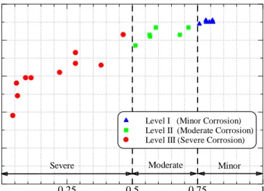
It is necessary to categorize the different corrosion conditions which can be seen in actual steel structures, into few general types for better understanding of their remaining strength capacities considering their visual distinctiveness, amount of corrosion and their expected mechanical and ultimate behaviors. The Figure 3 shows the relationship between the nominal ultimate stress ratio (σbn/σb) and the minimum thickness ratio (µ), where σbn is the nominal ultimate stress and σb is the ultimate stress of corrosion-free plate. Here, the minimum thickness ratio (µ) is defined as:
(1)
There, the initial thickness (t0) of the flange specimens and web specimens are 10.5mm and 10.0 mm respectively. Therefore, three different types of corrosion levels were identified according to their severity of corrosion and they are classified accordingly as follows:
µ > 0.75 ; Minor Corrosion 0.75 ≥µ≥ 0.5 ; Moderate Corrosion µ < 0.5 ; Severe Corrosion
Figure 3 Relationship of ultimate stress ratio & minimum thickness ratio (µ) µ , (tmin / t0) N o m in al U lt im at e S tr es s R at io , ( σbn / σb )
Level I (Minor Corrosion) Level II (Moderate Corrosion) Level III (Severe Corrosion)
Minor Moderate Severe 0 0.25 0.5 0.75 1 0.2 0.4 0.6 0.8 1
Figure 4: Plates with (a) minor corrosion (F-14), (b) moderate corrorion (F-13) and (c) severe
corrosion (F-19)
(a)
(b)
(c)
Displacement (mm) L o ad ( k N ) F-14 (Minor corrosion) F-13 (Moderate corrosion) F-19 (Severe corrosion) 0 10 20 30 40 50 60 50 100 150 200 250 300 350Figure 5: Load-displacement curves
Further, the Figure 4 shows three tensile test specimens with above three classified corrosion types. In minor corrosion type, it can be seen that many small corrosion pits were spread on all over the plate surface and an example of this corrosion type (F-14) is shown in Figure 4(a). When the corrosion is more progressed, the moderate corrosion type can be seen where few considerable corroded pits exist in some places. An example of this corosion type (F-13) is shown in Figure 4(b). Further, as the corrosion is more progressed than the moderate corrosion condition, severe corrosion type can be seen with several extensive corroded regions
(maximum corrosion depth over 5mm and the diameter of the corroded pits are exceeding 25mm) on the member. One example of severe corrosion type (F-19) is shown in Figure 4(c).
4.3. Experimental Results and Discussion
Figure 5 shows the Load-elongation curves for three different corroded specimens (F-14, F-13 and F-19) with 3 corrosion types. Herein, the specimen (F-14) with minor corrosion has almost same mechanical properties (such as apparent yield strength and load-elongation behavior etc.) as the corrosion-free specimen. On the other hand, the moderate corroded specimen (F-13) and the severe corroded specimen (F-19) show obscure yield strength and the elongation of the specimen F-19 decreases notably. The reason for this is believed to be that the local section with a small cross-sectional area yields at an early load stage
⋅ = y y y _ e
σ
B P t ⋅ = b b b _ eσ
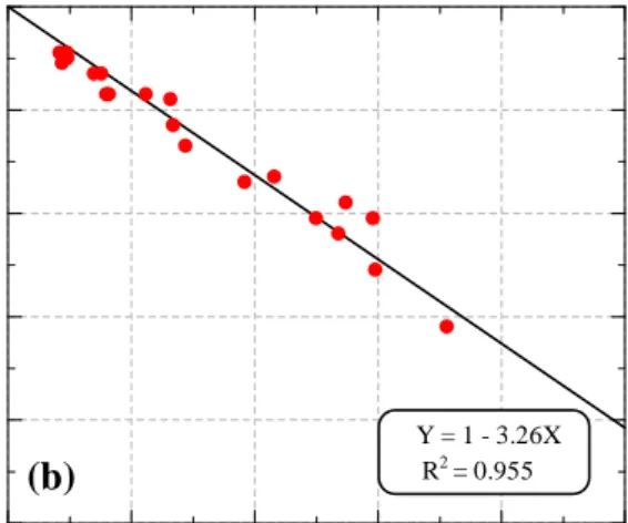
B P tFigure 6: Relationship of (a) yield stress ratio, (b) tensile stress ratio and normalized standard deviation of thickness (σst/t0)
Normalized standard deviation of thickness (σst/t0)
N o m in al y ie ld s tr es s ra ti o ( σyn / σy ) Y = 1 - 2.68X R2 = 0.921 0 0.05 0.1 0.15 0.2 0.25 0.2 0.4 0.6 0.8 1
Normalized standard deviation of thickness (σst/t0)
N o m in al t en si le s tr es s ra ti o ( σbn / σb ) Y = 1 - 3.26X R2 = 0.955 0 0.05 0.1 0.15 0.2 0.25 0.2 0.4 0.6 0.8 1
(a)
(b)
because of the stress concentration due to irregularity of corroded steel plate. And this will lead moderate and severe corroded members to elongate locally and reach to the breaking point.
5. Remaining Strength Estimation
The two basic definitions can be expressed for the experimentally predicted parameters for the yield effective thickness (te_y) and the tensile effective thickness (te_b) as follows:
(2)
(3) Where, Py: yield load, Pb: tensile load, B: width of the specimen for the corroded state and σy and σb are yield and tensile stress of corrosion-free plate respectively. But the above defined effective thickness parameters cannot be obtained for the in-service structures. So, a measurable statistical parameter with a high correlation with the effective thickness parameter will be essential for remaining strength estimation of those structures. Therefore, the correlations between the effective thickness (teff) and many measureable statistical parameters were examined (such as minimum thickness tmin, average thickness tavg, minimum average thickness tavg_min and standard deviation of thickness σst etc.) and two relationships were defined for remaining yield and ultimate strength estimations of corroded steel plates.
5.1. Estimation of Yield and Tensile Strengths
The correlation between the yield and tensile effective thickness and measureble statistical thickness parameters were examined and the best relationships were found with the standard deviation of thickness. The Figure 6(a) and Figure 6(b) show the two linear relationships obtained for yiled and tensile stress conditions.
So, considering the relationships shown in Figure 6, two equtionss for representative effective thickness (teff) for yield and tensile states can be obtained as described below.
−
=
0 st y ynt
68
.
2
1
σ
σ
σ
Tensile effective thickness, te_b (mm)
M in im u m t h ic k n es s, tm in ( m m ) 0 2 4 6 8 10 2 4 6 8 10
Tensile effective thickness, te_b (mm)
A v er ag e th ic k n es s, tav g ( m m ) 0 2 4 6 8 10 2 4 6 8 10
Tensile effective thickness, te_b (mm)
M in im u m a v er ag e th ic k n es s, tav g _ m in ( m m ) 0 2 4 6 8 10 2 4 6 8 10
Tensile effective thickness, te_b (mm)
P ro p o se d e ff ec ti v e th ic k n es s, tpro p o se d ( m m ) 0 2 4 6 8 10 2 4 6 8 10 (a) (b) (c) (d)
Figure 7: Relationship of (a) tmin vs te_b,(b) tavg vs te_b,(c) tavg_min vs te_b and (d) proposed effective thickness (teff) vs te_b
From Figure 6(a),
teff = t0 - 2.7σst (4) In same way from Figure 6(b),
teff = t0 - 3.3σst (5)
Further, the Figure 7 shows the relationship between different statistical thickness parameters with tensile effective thickness. It was found that the tensile strength estimation using minimum thickness (tmin) will provide considerably underestimated results as shown in Figure 7(a). On the other hand, Figure 7(b) shows that the average thickness (tavg) tends to become larger than effective thickness, as the influence of stress concentration due to corrosion will not be able to consider carefully. Figure 7(c) shows that the minimum average thickness (tavg_min) also gives larger values than the effective thickness and hense, the strength estimation using only tavg or tavg_min will overestimate the remaining tensile strength. This will lead the structure in danger on decissision taken regading its maintenace management plan. But, as it can be seen from Figure 7(d), the proposed effective thikness gives more accurate and better remaining strengths estimation.
Table 1: Comparison of correlation coefficients of different effective thickness prediction methods
Method
Matsumoto
et al. 1989
Muranaka
et al. 1998
Kariya
et al. 2003
Proposed,
t
effEquation of thickness
t
sat
avg– 0.7
σ
stt
avg– 1.3
σ
stYield: t
0– 2.7
σ
stTensile: t
0– 3.3
σ
stCorrelation
Coefficient
Yield
–
–
–
0.92
Tensile
0.70
0.14
0.75
0.96
5.2. Comparison of Proposed Effective Thickness
The Table 1 shows that the proposed effective thickness parameter gives more reliable and better prediction than other available methods for estimating remaining yield and tensile strengths.
6.
Conclusions
The steel surface measurements and tensile tests were conducted on many wide specimens with different corrosion conditions, which are obtained from a plate girder which had been used for about 100 years with severe corrosion. The main conclusions of this study can be summarized as:
(1) The corrosion causes strength reduction of steel plates and minimum thickness ratio (µ) can be used as a measure of the level of corrosion and their strength degradation. Three basic corrosion categories can be defined according to their severity of corrosion as, minor corrosion (µ > 0.75), moderate corrosion (0.75 ≥µ≥ 0.5) and severe corrosion (µ < 0.5).
(2) Remaining yield strength of corroded steel plates can be estimated by using the representative effective thickness defined as: teff = t0 - 2.7σst with high accuracy.
(3) The remaining tensile strength estimation can be done by using the representative effective thickness defined as: teff = t0 - 3.3σst with high accuracy.
7.
Acknowledgements
The authors would like to thank the technical staffs of Mitutoyo Corporation (Japan) for their assistance in surface measurement of corroded specimens.
References
‘Corrosion Protection of Steel Bridges’, Steel Bridge Design Handbook, Chapter 23, National Steel Bridge Alliance.
Kaita, T., Fuji, K., Miyashita, M., Uenoya, M., Okumura, M. and Nakamura, H. (2005), ‘An Experimental Study on the residual bending strength of corroded plates’, Proceedings of Structural Engineering, Vol.51A, pp.139-148.
Kariya, A., Tagaya, K., Kaita, T. and Fujii, K. (2003), ‘Basic study on effective thickness of corroded steel plate and material property’, Annual conference of JSCE, pp 967-968. (In Japanese)
Kariya, A., Tagaya, K., Kaita, T. and Fujii, K. (2005), ‘Mechanical properties of corroded steel plate under tensile force’, Proceedings of the 3rd International Structural Engineering and Construction Conference (ISEC-03), Japan, pp 105-110. Matsumoto, M., Shirai, Y., Nakamura, I. and Shiraishi, N. (1989), ‘A Proposal of effective Thickness Estimation Method of
Corroded Steel Member’, Bridge Foundation Engineering, vol. 23, No. 12, pp 19-25. (In Japanese)
Muranaka, A., Minata, O. and Fujii, K. (1998), ‘Estimation of residual strength and surface irregularity of the corroded steel plates’, Journal of Structural Engineering, vol. 44A, pp 1063-1071 (In Japanese).