Abstract—The continuous innovations and advances in both high-end mobile devices and wireless communication technologies have increased the users demand and expectations for anywhere, anytime, any device high quality multimedia applications provisioning. Moreover, the heterogeneity of the wireless network environment offers the possibility to the mobile user to select between several available radio access network technologies. However, selecting the network that enables the best user perceived video quality is not trivial given that in general the network characteristics vary widely not only in time but also depending on the user location within each network. In this context, this paper proposes a user location-aware reputation-based network selection solution which aims at improving the video delivery in a heterogeneous wireless network environment by selecting the best value network. Network performance is regularly monitored and evaluated by the currently connected users in different areas of each individual network. Based on the existing network performance-related information and mobile user location and speed, the network that offers the best support for video delivery along the user’s path is selected as the target network and the handover is triggered. The simulation results show that the proposed solution improves the video delivery quality in comparison with the case when a classic network selection mechanism was employed.
Keywords-Heterogeneous wireless networks, media independent handover (MIH), network selection, quality-of-service (QoS)adaptive video delivery, user mobility.
I. INTRODUCTION
here is an increasing desire to enable the “always best connected” paradigm given todays’ heterogeneous wireless network environment. However, supporting such a connectivity goal and enabling very good quality of rich media mobile services anywhere and anytime is very difficult, mostly due to system complexity and diversity of technologies.
This work was supported by the Irish Research Council Enterprise Partnership with Everseen Ltd.
Ting Bi, Ramona Trestian and Gabriel-Miro Muntean are with the Performance Engineering Laboratory, Network Innovations Centre, the RINCE Research Institute, School of Electronic Engineering, Dublin City University, Ireland (phone: +353-1-700-7643; e-mail: [email protected], {ramona, munteang}@eeng.dcu.ie).
In terms of video delivery over wireless networks, there are three major access network technologies which enable this: broadband, cellular and broadcast. Broadband wireless networks are mostly represented by the IEEE 802.11 family (i.e. including the best known 802.11 a/g/b/n and the recent IEEE 802.11 ac) and offer high data delivery rates, but have limited range. Cellular networks, best known for their Global System for Mobile Communications (GSM) and Universal Mobile Telecommunications System (UMTS) technologies, support wider signal coverage areas but lower average data rates when compared to the IEEE 802.11 family. The latest Long-Term-Evolution (LTE) standard provides support for higher data rates which could reach up to 3 Gbps downlink and 1.5 Gbps uplink [1]. Broadcast networks are mostly used for distributing video in downlink mode to a large number of users.
In this heterogeneous wireless network environment there is an increasing number of mobile users requesting mainly video-based applications. However, most of the rich-media applications require high data rates, low delays and low loss rates as basic requirements, in order to offer high levels of users Quality of Experience (QoE).
Because of the user mobility within this heterogeneous environment, they regularly require network selection and handover procedures in order to maintain their seamless connectivity to the Internet. Additionally to support best user perceived video quality level for their multimedia-based application, the selection of the most appropriate network in terms of performance is required. Choosing the right network is not trivial as network characteristics vary widely not only
Reputation-based Network Selection Solution
for Improved Video Delivery Quality in
Heterogeneous Wireless Network Environments
Ting Bi, Ramona Trestian,
Member, IEEE
and Gabriel-Miro Muntean,
Member, IEEE
T
in time, but also depending on user location within each network. Predicting the performance of candidate networks is very difficult based on a single user device gathered data, fact that makes the selection of the best value network challenging. In this context, this paper proposes a novel Reputation-based Network Selection solution (RNS) that enables the selection of the best value network for multimedia transmission. RNS, based on the IEEE 802.21 MIH standard mechanisms, supports gathering of delivery performance information from the currently connected users from different areas within each network. The information is aggregated and disseminated to other mobile users, which can make an informed quality-oriented decision when selecting the candidate network for handover.
The rest of the paper is organized as follows. Section II discusses related works. Section III presents detailed information about the RNS system architecture and section IV presents the RNS algorithms. Section V introduces the simulation scenarios and will analyze the simulation results. Section VI presents the conclusions and future work directions.
II. RELATED WORK
In order to improve Quality of Service (QoS) and enable seamless handover between heterogeneous wireless networks, IEEE has developed the 802.21 Media Independent Handover (MIH) standard [2]. The MIH framework defines a cross-layer MIH function (MIHF) as a logical component between network layer and link layer. MIHF provides three independent services: media independent event service (MIES), media independent command service (MICS), and media independent information service (MIIS). The MIH framework also defines a MIH information server, which uses MIES via a MIHF interface to exchange information about various networks and mobile nodes. The MIH Information Server itself does not provide any network selection algorithm however if offers the support for the mobile nodes to perform network selection and seamless handover.
An enhanced MIH Information Server to accelerate vertical handover procedures in the 802.21 framework was proposed in [3].
For executing a smooth handover, selection of an appropriate network is fundamental. Unfortunately the 802.21 MIH protocol does not directly provide network selection mechanisms, but assists them. An energy-aware utility-based user-centric network selection strategy in heterogeneous wireless network environments was proposed in [4]. This strategy uses the MIHF to gather and exchange information about the available wireless networks.
Some other papers [5-7] have also addressed the network selection problem in the heterogeneous wireless network environments.
In order to maximize the system sum-rate under a proportional user rate constraint, a suboptimal radio-resource management (RRM) algorithm with lower
complexity and similar performance to previous algorithms was proposed for LTE-WLAN heterogeneous networks. The authors in [6] have proposed a Signal to Interference-plus-Noise Ratio (SINR)-based network selection strategy which allows users to select the highest SINR value network from a number of available networks. The authors in [7] have proposed a route-selection algorithm for forwarding packet in the ad-hoc mode and a Vertical Handoff Decision (VHD) algorithm with applicability to 3/4G-WLAN or VANET heterogeneous wireless networks. The VHD algorithm enables balancing the overall load among all base stations and access points, and aims at maximizing the collective battery lifetime of the mobile nodes.
The authors in [8] propose a reputation-based network selection mechanism that makes use of game theory in order to model the user-network interaction as a repeated cooperative game. The network reputation is computed based on the user’s payoff. Their proposed solution is based on individual user experience and the mechanism is integrated into an extended version of the IEEE 802.21 model.
In all these previous related works, multi-user involvement in information gathering or network reputation building and reputation information exchange has not been considered. The focus of this paper is on using multi-user involvement in the reputation-based network selection (RNS) process in order to select the most appropriate network for a certain user. The RNS mechanism is based on user location, signal strength and delay information, which are gathered on the MIH Information Server and shared among mobile nodes. These are the main contributions of this paper.
III. RNS ARCHITECTURE
A. Overview
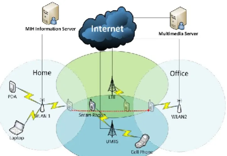
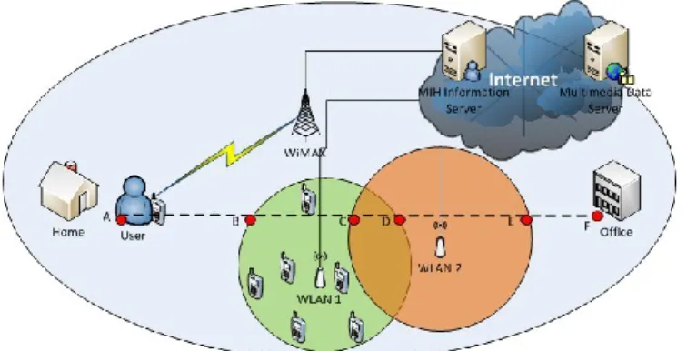
Fig. 1 shows a heterogeneous wireless network environment in which for example, a Mobile Node (MN)
Network MIH Function Layer 1 & 2 Layer 2.5 Layer 3 & 4 Upper Layers MIH Function Layer 1 & 2 Layer 2.5 Layer 3 & 4 Upper Layers Mobile Node
MIH Information Server
802 Interface MIH-LINK-SAP NetWork Selection Algorithm MIH-SAP MIH-SAP Network Raputation Algorithm Localiztion Prediction Algorithm 3G/LTE Interface MIH Function Layer 1 & 2 Layer 2.5 Layer 3 & 4 Upper Layers Multimedia Server MIH-SAP Adaptive Data Deliver Algorithm MIH-NET-SAP Data CONTROL
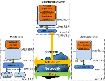
(e.g. a smart device) can be located in a home Wireless Local Area Network (WLAN) coverage area. Following user mobility, MN can face the choice of selecting between WLAN, UMTS, and LTE access networks. . The MN has to select the appropriate network in order to continue the Internet connectivity and receive the video data. In order to enable high quality video delivery independent from the network attached to, we propose the reputation-based network selection solution (RNS) for MN. The RNS block-level architecture is illustrated in Fig. 2.
This system architecture consists of three main components: Mobile Nodes (MN), a MIH Information Server and a Multimedia Server. The detail description of each of these components is presented next.
In order to perform network selection, the MN needs the list of candidate networks and also their associated quality levels. IEEE 802.21 MIH provides a mechanism to support gathering and exchanging of information between various candidate networks, the MIH Information Server and the MN. Each of the MIH-enabled entities contains a cross-layer MIHF. This function provides Service Abstraction Points (SAP) acting as an abstract interface between a service provider and a user entity. The higher-layer user entities employ the MIH-SAP to control or monitor the link-layer entity, and the MIHF uses the MIH-LINK-SAP as an interface together with the link layer to translate the comment received from the MIH-SAP. The remote MIHF entities use the MIH-NET-SAP to exchange the information with the MIHF.
In the proposed RNS, MN uses the MIH-NET-SAP to send information request or to report to the MIH Information Server via the current serving network. Then the MIH
Information Server sends a response back to the MN. Meanwhile, the MIH Information Server sends a report to the multimedia server. Based on the information contained in the response, MN executes the network selection algorithm choosing the best candidate network and executes handover. Fig. 3 shows the detailed handover process. Meanwhile, the Multimedia Server receives a user report from the MIH Information Server and performs adaptive data delivery according to the report. Once the handover process is complete, MN receives video data from the Multimedia Server via the new network.
B. Mobile Node
MN is an entity requesting and receiving multimedia data capable of making network selection decision and executing handover. In the context of RNS, MN is involved in a dual request-report process described next:
1. Requesting
For the purpose of network selection, MN sends an information request to the current serving attachment point when it initiates a connection with the current serving network. The current serving network forwards this information request to the MIH information server.
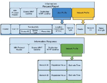
The information request follows the 802.21 MIH protocol packet structure, and contains at least three fields: the MIH Protocol header, Source MIHF Identifier and Destination MIHF Identifier. In this paper, two extra specific fields are added as illustrated in Fig. 4: User Profile and Network Profile to describe both user and network characteristics.
2. Reporting
In the context of RNS, MN sends user reports together with every information request. Additionally user reports are generated and sent to the MIH Information Server regularly. The user report has the same structure with the
Figure 4. Structure of the information request and response
information request except that in the User Profile field, terminal information is not included.
C. MIH Information Server
The MIH Information Server receives information requests, and user reports from MNs and network reports from the candidate networks using MIH-NET-SAP. On receiving any information, MIH Information Server sends it from MIHF to the upper-layers in charge with network selection-related data storage and processing, and immediately responds to MN. The information response extends the 802.21 MIH protocol with one additional field: Network Profile. This field lists a subset of candidate networks as along with values representing their reputation and time instances at which user localization prediction is fulfilled.
All the information about users and networks is stored into a specific database. The MIH Information Server data structure is shown in Fig. 5.
D. Multimedia Server
The Multimedia Server is the entity which delivers media data to MNs and receives reports from the MIH Information Server about the state of MN and network. In this RNS-based system, Quality-Oriented Adaptation Scheme (QOAS) [9] is employed for high quality adaptive video delivery. The control information exchange from MN to the Multimedia Server follows the 802.21 MIH protocols. The packet structure includes an additional field with the score grading video quality of delivery.
IV. RNS ALGORITHMS
This work proposes a Network Reputation Algorithm (NRA) which based on network profile information collected from multiple user reports computes a network reputation value. The granularity of reputation computation is at the level of a network sector, providing higher
precision given real network delivery situations. An Overall Network Reputation Algorithm (ONRA) puts together the reputations of the different sectors within the same network and calculates the overall network reputation. A Localization Prediction Algorithm (LPA) is also introduced which uses the location information from user reports to estimate user route and therefore future user position relative to various networks’ coverage areas. This is used in the network selection process. These algorithms are described next. Based on NRA and LPA, the Network Selection Algorithm (NSA) is introduced to suggest the best network from the candidate networks to connect to in terms of performance.
A. Network Reputation Algorithm 1) Network Quality Reporting
The Network Reputation Algorithm (NRA) gathers the information from multiple requests and reports. In order to execute the algorithm, the data required includes: current access point (AP) location (Xap, Yap), MN location (Xmn, Ymn), and signal strength measured at user’s current location
.
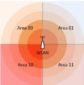
In the algorithm, the network coverage is divided into N sectors, where N=2x, x= {0, 1, 2…n}. Each sector (area) has an independent reputation value related to the signal strength, which significantly influences video delivery quality. Fig. 6 shows an example for x=2 (N=4).
Based on the coordinates of MN location and knowing the position of the AP in terms of coordinates , the AreaID can be found using equation (1):
(1)
For the case with the 4 areas, equation (1) becomes: Figure 6. Network signal strength map for 4 areas Figure 5. Structure of the Data Saved at the MIH Information Server
{ (2)
The theoretical value of the signal strength of user’s location is calculated based on distance D between AP and MN by using the signal strength equation described in [3] [10][11] and in equation (3) :
10 10 10 10 ( ) 46.3 33.9log ( ) 13.82log ( ) ( ) (44.9 6.55log ( ))log ( ) dB b r b m PL D f h a h h d c (3)
In equation (3), f is the carrier frequency, hb is the antenna height at the AP, and d is the distance between the AP and MN. a(hr) is the MN’s antenna height correction factor and hr is the MN’s antenna height. The parameter cm is a constant with values 3 dB and 0 dB for urban and suburban environments, respectively.
(4) where PtdB is the transmit power expressed in dB. The distance D between AP and MN is computed according the equation (5):
√( ) (5)
Finally, the utility value USS for the current user in its position is computed using
and equation (6).
(6) The user regularly sends reputation reports (URR) which can be described as multi-tuple as in equation (7):
(7)
where MNID, NetworkID and AreaID are IDs which identify mobile node, network and sector within the network Uss is computed for at the given MN position.
2) Network Reputation Algorithm
NRA is presented in pseudo code in Algorithm 1. It describes how the reputation value Ui,j
R for each network area j of each network i can be generated given the utility function value Uss received from any reporting node located in that area. NRR is the number of reputation reports received so far.
Algorithm 1: Network Reputation Algorithm 1: If (first report) then
2: Initialize NRR=0 3: if ( ) then 4: 𝑅𝑖 𝑗 ; 5: else 6: 𝑅𝑖 𝑗 U𝑅𝑖 𝑗∗𝑁𝑅𝑅+U𝑠𝑠 NRR+1 ; 7: end if 8: ++;
3) Overall Network Reputation Algorithm
The Overall Network Reputation Algorithm (ONRA), presented in pseudo code in Algorithm 2, describes how the reputation value UiR for network i can be calculated given the reputation values of all the sectors j within network i Ui,j
R. NAR is the number of network sectors.
Algorithm 2: Overall Network Reputation Algorithm
1: for each sector j of network i
2: 𝑅𝑖 ∑ U𝑅
𝑖 𝑗
NAR
3: end for
B. Localization Prediction Algorithm
The Localization Prediction Algorithm (LPA), presented in Algorithm 3, estimates the position of MN at the moment
t+∆t, given the position of the node until moment t. LPA collects user location information from both the information requests and user reports. Each piece of location information stored in the database is associated with a timestamp. LPA is applied for a MN if the number of location information entries stored in database is greater than 2. LPA then computes MN’s speed based on both spatial distance between the entries and timestamp difference. The distance is calculated based on equation (5) considering two consecutive MN positions and the direction of travel. Next, by using the timestamps, the MN's speed is determined and the location of MN can be estimated at moment t+∆t. The accuracy of the prediction is improved when the number of the location information stored in the database is increased. Algorithm 3: Localization Prediction Algorithm
1: For (i=0,i<No.E)
2: Compute Di using coordinate 𝑖 and 𝑖+1 by equation (5). 3: Calculate Vi 𝑖 𝑖 𝑖+1 𝑖 4: For (i=0,i<No.E)
5: Determine𝑉̅ using {V1,V2,…,VNo.E}
̅ ∑ 𝑉𝑖
𝑁𝑜.𝐸 𝑖 . 𝐸
6: Get 𝑉̅ , tNo.E, .𝐸 .𝐸 and ∆t compute ′ at time tNo.E+∆t
In Algorithm 3, No.E is the number of location information entries stored in the database.
C. Network Selection Algorithm
The Network Selection Algorithm (NSA), presented in Algorithm 4, selects the best network from the candidate network list in terms of performance. The performance of each candidate network i is estimated based on a utility function Ui, which is composed of the signal strength utility Ui
R and a network serving response utility UiT. This function can be described in equation (8):
𝑖 ∗
𝑅∗ 𝑅 (8)
Where: i – the candidate network, Ui– overall utility for network i, and WR and WT are weights for signal strength and network serving response utilities, respectively.
Algorithm 4: Network Selection Algorithm
1: Initialize trequest, tresponse, RN, 𝑟𝑒𝑞 𝑒 and
𝑟𝑒 𝑜 𝑒 ; 2: Compute RTT=tresponse-trequest;
3: Calculate DR using coordinates, 𝑟𝑒𝑞 𝑒 and 𝑟𝑒 𝑜 𝑒 and equation (5).
4: Get 𝑉𝑅 𝑅 𝐷𝑅; 5: Estimate 𝑇𝐸𝑖 𝑅𝑁 𝑖 𝑉𝑅; 6: Determine 𝑖 log 10( 𝐸 𝑖 𝑅 ) 7: For (i=0,i<No.CN)
8: Calculate Ui using equation (8)
9: Selected the maximum 𝑥𝑖 from{ 1 … 𝑁𝑜.𝐶𝑁} In Algorithm 4, RN is the cell radius of network, No.CN
is the number of the candidate networks, 𝑟𝑒 𝑜 𝑒 𝑟𝑒 𝑜 𝑒 are the coordinates MN’s position when it receives a response, DR is the distance MN moved during RTT, VR is the average speed when MN moved during RTT, and TiE is the maximum server time for each network i.
NSA is executed when either MN finds new candidate networks or part of a regular process meant to maintain the node best connected. Either way, in order to assess the reputation of the candidate networks, MN sends a request to the MIH Information Server with the list of candidate networks, timestamp trequest, MN’s position 𝑟𝑒𝑞 𝑒 𝑟𝑒𝑞 𝑒 and signal strength at this position in the current network. The MIH Information Server will send back to MN an information response containing: the reputation report for the list of candidate networks, including reputation values Ui
R for each candidate network i. and timestamp tresponse. Handover will be performed to the the network with the highest utility value as selected by NSA.
V. SIMULATION-BASED TESTING A. Scenario Description
The performance of the proposed Reputation-based Network Selection solution (RNS) was evaluated using Network Simulator 3 (NS-3) version 3.15. RNS was compared against a classic Network Selection (NS) which always will select the free hot spots. The proposed algorithm was analyzed using a scenario from a typical day in a business professional life, who travels from home (point A) to his office (point F) as illustrated in Figure 7. On his way to the office the user accesses interactive multimedia services through his multi-interface mobile device (e.g., WiMAX and WLAN) from the multimedia server. While on the move, the user passes through the coverage area of several different radio access technologies. First the user is connected to the WiMAX network which has the widest range (point A). As he passes through the areas with a number of other available networks (e.g., WLAN 1 and WLAN 2), a network selection decision has to be made at the following points: B, C, D, and E as marked in Figure 7. Both WLAN 1 and WLAN 2 are assumed to be free hot spots where WLAN 1 is heavily loaded with other six extra users generating background traffic at 1.5Mbps. Furthermore, it is assumed that the business professional is accessing video on demand services at a data rate of 2Mbps.
B. Results
On the way to the office, the user enables the RNS algorithm on his mobile device. The RNS algorithm computes a reputation values for each of the candidate networks as listed in Table I.
TABLE I. NETWORK REPUTATION
Networks WiMAX WLAN 1 WLAN 2 Reputation Value Ui 1.01 0.93 1.11
The user if first connected to WiMAX in point A, and as he follows his path to the office he reaches point B where another network (e.g., WLAN 1) is available. The classic NS will handover to WLAN 1 as it is set to always select
the free hot-spot. The reputation value of WLAN 1 is computed by the proposed RNS algorithm using the feedback of the already connected users. Being heavily loaded WLAN 1 will get a low reputation in comparison to WiMAX. Thus the RNS algorithm decides to maintain the connection with WiMAX. As the user moves along his path, he reaches point C where he has a choice of three available networks: WiMAX, WLAN 1 and WLAN 2. At this point, RNS decides to handover to WLAN 2 which has a better reputation, whereas the classic NS maintains the connection to WLAN 1, handing over to WLAN 2 only when the user reaches point D. After the user moves away from the coverage area of WLAN 2 in point E, his session will be transferred to WiMAX again.
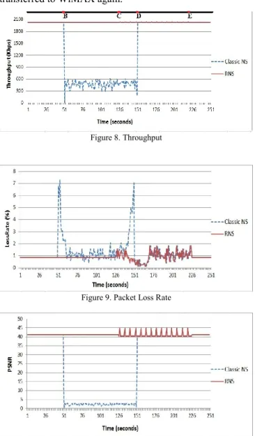
Figure 8. Throughput
Figure 9. Packet Loss Rate
Figure 10. Estimated user perceived quality using PSNR (dB)
TABLE II. SIMULATION RESULTS RNS VS. CLASSIC NS Classic NS RNS Benefit (%) Average throughput (Kbps) 1406 2029 44.36 Standard deviation of throughput (Kbps) 767.80 1.86 99.76 Average loss rate (%) 1.22 0.90 26.00 Standard deviation of loss rate 1.01 0.28 72.57 Average PSNR (dB) 25.55 41.09 60.84 Standard deviation of PSNR 19.06 1.047 94.51
The throughput and the packet loss ratio for the simulated scenario are illustrated in Figure 8 and Figure 9, respectively.
The Peak Signal to Noise Ratio (PSNR) was computed using the equation proposed in [12] and represents an estimation of the end-user perceived quality level. The PSNR is illustrated in Figure 10.
Figures 8, 9 and 10 compare the proposed RNS and the classic NS solution. Additionally, average results for the simulation scenario considered are listed in Table II. The results show that by using the proposed RNS the user gains 44.36% in terms of throughput and records 26% decrease in packet loss ratio, and 60.84% increase in PSNR.
VI. CONCLUSIONS AND FUTURE WORK
This paper proposes a user location-aware reputation-based network selection solution (RNS) for improving video delivery in a heterogeneous wireless network environment. Based on the device profiles, user reputation reports and network conditions, the reputation of the candidate networks are computed. The network reputations are then used in the network selection decision in order to select the most appropriate network for the user. The results show that the proposed solutions can achieve up to 44% increase in throughput, 26% decrease in packet loss ratio and up to 61% increase in PSNR, when compared against a classic network selection algorithm.
In terms of future work, additional parameters and improvements could be integrated into the current solution in order to enhance mobile user experience levels. Different studies have shown that the overall user experience may be affected by a wide range of factors. For example, at the network operator side, different pricing models for various classes of service could be considered by predicting the economic behavior of the users [13] and by taking into account users’ attitude towards risk [14] while performing service delivery. Additionally, utility functions could be integrated to map the received bandwidth on user satisfaction for multimedia streaming applications [15-17].
ACKNOWLEDGMENT
The support of the Irish Research Council and Everseen Ltd. is gratefully acknowledged.
REFERENCES
[1] LTE-Advanced Rapporteur, “RP-090939: 3GPP Submission Package for IMT-Advanced”, www.3gpp.org, 3GPP TSG RAN, meeting 45, Seville, Spain, September 2009.
[2] IEEE 802.21-2008, Standard for Local and Metropolitan Area Networks-Part 21: Media Independent Handover Services, IEEE Computer Society, Jan. 2009.
[3] Y. Kim, S. Pack, C. G. Kang, and S. Park, “An Enhanced Information Server for Seamless Vertical Handover in IEEE 802.21 MIH Networks”, Elsevier Computer Networks, vol. 55, no. 1, pp. 147–158, 2011.
[4] R. Trestian, O. Ormond, and G-M. Muntean, “Power-friendly Access Network Selection Strategy for Heterogeneous Wireless Multimedia Networks”, IEEE International Symposium on Broadband Multimedia Systems and Broadcasting (BMSB), pp. 1–5, 2010. [5] P. Xue, P. Gong, J. H. Park, D. Park, and D. K. Kim, “Radio
Resource Management with Proportional Rate Constraint in the Heterogeneous Networks” IEEE Transactions on Wireless Communications, vol. 11, no. 3, pp. 1066–1075, 2012.
[6] A. Jabban, Y. Nasser, and M. Helard, “SINR-based Network Selection Strategy in Integrated Heterogeneous Networks”, the19th International Conference on Telecommunications, (ICT), pp. 1–5, 2012.
[7] K. Sriram, and N. Golmie, “Vertical Handoff Decision Algorithms for Providing Optimized Performance in Heterogeneous Wireless Networks”, IEEE Transactions on Vehicular Technology, vol. 58, no. 2, pp. 865–881, 2009.
[8] R. Trestian, O. Ormond, and G-M. Muntean, “Reputation-based Network Selection Mechanism using Game Theory,” Physical Communication, vol. 4, no. 3, pp. 156–171, Sep. 2011.
[9] G.-M. Muntean, P. Perry, and L. Murphy, “Quality-Oriented Adaptation Scheme (QOAS) for High Bit-rate Multimedia Streaming”, Proc. 6th International Conference on Technical Informatics (CONTI), vol. 4, pp. 199-204, 2004.
[10] R. Trestian, O. Ormond, and G.-M. Muntean “Signal Strength-based Adaptive Multimedia Delivery Mechanism”, the 34th IEEE Conference on Local Computer Networks (LCN), Zürich, pp.297–300, 2009.
[11] COST ACTION 231, “Digital Mobile Radio Towards Future Generation System,” Technical Report, European Community, 1999. [12] S.-B. Lee, G.-M. Muntean, A. F. Smeaton, “Performance-Aware
Replication of Distributed Pre-Recorded IPTV Content”, IEEE Transactions on Broadcasting, vol. 55, no. 2, pp.516-526, Jun. 2009. [13] A. Molnar and C. H. Muntean “Mobile Learning: An Economic
Approach”, in S. Graf, F. Lin, Kinshuk, & R. McGreal (Eds.),
Intelligent and Adaptive Learning Systems: Technology Enhanced Support for Learners and Teachers, pp. 311-326, 2012
[14] A. Molnar and C. H. Muntean, “Consumer’ Risk Attitude-based Personalisation for Content Delivery,” in IEEE Consumer Communications and Networking Conference (CCNC), 2012. [15] R. Trestian, A. N., Moldovan, C. H. Muntean, O. Ormond, and G.-M.
Muntean, “Quality Utility Modelling for Multimedia Applications for Android Mobile Devices”, IEEE International Symposium on
Broadband Multimedia Systems and Broadcasting (BMSB), 2012.
[16] G.-M. Muntean, L. Murphy, “Adaptive Pre-recorded Multimedia Streaming, IEEE Global Telecommunications Conference (Globecom), vol. 2, pp. 1728-1732, 2002
[17] C. Xu, E. Fallon, Y. Qiao, L. Zhong, G.-M. Muntean, “Performance Evaluation of Multimedia Content Distribution over Multi-homed Wireless Networks”, IEEE Transactions on Broadcasting, vol. 57, no. 2, pp. 204-215, 2011