TECHNICAL
REPORT
IEC
TR 61131-8
Second edition 2003-09Programmable controllers –
Part 8:
Guidelines for the application and implementation
of programming languages
Automates programmables –
Partie 8:
Lignes directrices pour l'application et la mise en oeuvre
des langages de programmation
Reference number IEC/TR 61131-8:2003(E)
Copyright International Electrotechnical Commission
Provided by IHS under license with IEC Licensee=Technip Abu Dabhi/5931917101
--``,`,`,,,``````,,``,,``,,,,`,-`-`,,`,,`,`,,`---As from 1 January 1997 all IEC publications are issued with a designation in the 60000 series. For example, IEC 34-1 is now referred to as IEC 60034-1.
Consolidated editions
The IEC is now publishing consolidated versions of its publications. For example, edition numbers 1.0, 1.1 and 1.2 refer, respectively, to the base publication, the base publication incorporating amendment 1 and the base publication incorporating amendments 1 and 2.
Further information on IEC publications
The technical content of IEC publications is kept under constant review by the IEC, thus ensuring that the content reflects current technology. Information relating to this publication, including its validity, is available in the IEC Catalogue of publications (see below) in addition to new editions, amendments and corrigenda. Information on the subjects under consideration and work in progress undertaken by the technical committee which has prepared this publication, as well as the list of publications issued, is also available from the following:
• IEC Web Site (www.iec.ch) • Catalogue of IEC publications
The on-line catalogue on the IEC web site (www.iec.ch/searchpub) enables you to search by a variety of criteria including text searches, technical committees and date of publication. On-line information is also available on recently issued publications, withdrawn and replaced publications, as well as corrigenda. • IEC Just Published
This summary of recently issued publications (www.iec.ch/online_news/ justpub) is also available by email. Please contact the Customer Service Centre (see below) for further information.
• Customer Service Centre
If you have any questions regarding this publication or need further assistance, please contact the Customer Service Centre:
Email: [email protected]
Tel: +41 22 919 02 11 Fax: +41 22 919 03 00
Copyright International Electrotechnical Commission
Provided by IHS under license with IEC Licensee=Technip Abu Dabhi/5931917101
--``,`,`,,,``````,,``,,``,,,,`,-`-`,,`,,`,`,,`---TECHNICAL
REPORT
IEC
TR 61131-8
Second edition 2003-09Programmable controllers –
Part 8:
Guidelines for the application and implementation
of programming languages
Automates programmables –
Partie 8:
Lignes directrices pour l'application et la mise en oeuvre
des langages de programmation
PRICE CODE
IEC 2003 Copyright - all rights reserved
No part of this publication may be reproduced or utilized in any form or by any means, electronic or mechanical, including photocopying and microfilm, without permission in writing from the publisher.
International Electrotechnical Commission, 3, rue de Varembé, PO Box 131, CH-1211 Geneva 20, Switzerland Telephone: +41 22 919 02 11 Telefax: +41 22 919 03 00 E-mail: [email protected] Web: www.iec.ch
XD
For price, see current catalogue Commission Electrotechnique InternationaleInternational Electrotechnical Commission Международная Электротехническая Комиссия
Copyright International Electrotechnical Commission
Provided by IHS under license with IEC Licensee=Technip Abu Dabhi/5931917101
--``,`,`,,,``````,,``,,``,,,,`,-`-`,,`,,`,`,,`---CONTENTS
FOREWORD ... 6 INTRODUCTION ... 8 1 General... 9 1.1 Scope ... 9 1.2 Normative references... 9 1.3 Abbreviated terms ... 9 1.4 Overview ...10 2 Introduction to IEC 61131-3...10 2.1 General considerations ...102.2 Overcoming historical limitations ...12
2.3 Basic features in IEC 61131-3 ...13
2.4 New features in the second edition of IEC 61131-3...14
2.5 Software engineering considerations ...14
2.5.1 Application of software engineering principles...14
2.5.2 Portability...17
3 Application guidelines ...18
3.1 Use of data types ...18
3.1.1 Type versus variable initialization ...18
3.1.2 Use of enumerated and subrange types...18
3.1.3 Use of BCD data ...19
3.1.4 Use of REAL data types ...21
3.1.5 Use of character string data types ...21
3.1.6 Use of time data types...23
3.1.7 Declaration and use of multi-element variables ...23
3.1.8 Use of bit-string functions...24
3.1.9 Strongly typed assignment...25
3.2 Data passing...26
3.2.1 Global and external variables ...27
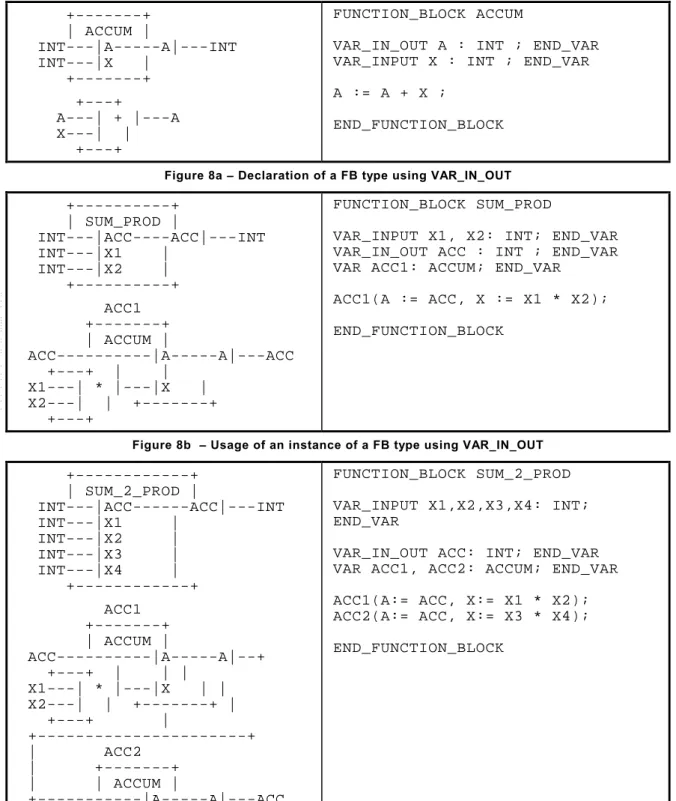
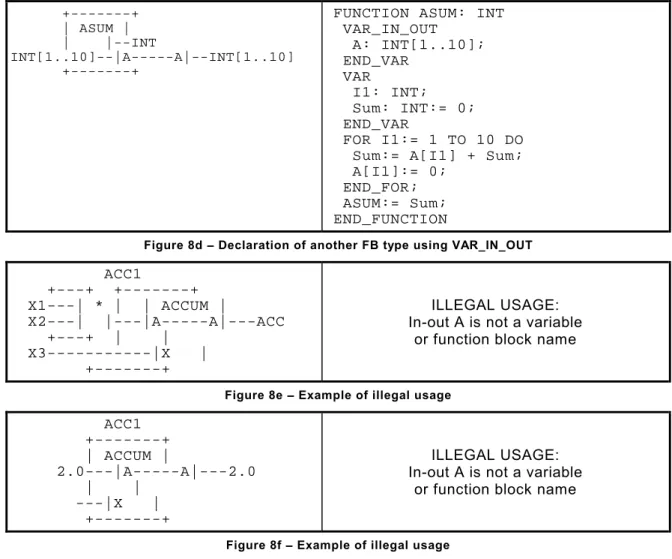
3.2.2 In-out (VAR_IN_OUT) variables...27
3.2.3 Formal and non-formal invocations and argument lists...30
3.3 Use of function blocks ...32
3.3.1 Function block types and instances ...32
3.3.2 Scope of data within function blocks ...33
3.3.3 Function block access and invocation ...34
3.4 Differences between function block instances and functions ...35
3.5 Use of indirectly referenced function block instances ...35
3.5.1 Establishing an indirect function block instance reference...35
3.5.2 Access to indirectly referenced function block instances ...37
3.5.3 Invocation of indirectly referenced function block instances ...38
3.5.4 Recursion of indirectly referenced function block instances...40
3.5.5 Execution control of indirectly referenced function block instances...40
3.5.6 Use of indirectly referenced function block instances in functions...40
3.6 Recursion within programmable controller programming languages ...41
3.7 Single and multiple invocation ...41
Copyright International Electrotechnical Commission
Provided by IHS under license with IEC Licensee=Technip Abu Dabhi/5931917101
--``,`,`,,,``````,,``,,``,,,,`,-`-`,,`,,`,`,,`---TR 61131-8 IEC:2003(E) – 3 –
3.8 Language specific features ...42
3.8.1 Edge-triggered functionality ...42
3.8.2 Use of EN/ENO in functions and function blocks ...43
3.8.3 Use of non-IEC 61131-3 languages ...44
3.9 Use of SFC elements ...45 3.9.1 Action control ...45 3.9.2 Boolean actions ...46 3.9.3 Non-SFC actions ...49 3.9.4 SFC actions ...51 3.9.5 SFC function blocks ...51 3.9.6 “Indicator” variables ...52
3.10 Scheduling, concurrency, and synchronization mechanisms...52
3.10.1 Operating system issues ...52
3.10.2 Task scheduling ...54
3.10.3 Semaphores...55
3.10.4 Messaging ...56
3.10.5 Time stamping ...56
3.11 Communication facilities in ISO/IEC 9506/5 and IEC 61131-5 ...57
3.11.1 Communication channels ...57
3.11.2 Reading and writing variables ...57
3.11.3 Communication function blocks ...58
3.12 Deprecated programming practices ...59
3.12.1 Global variables ...59
3.12.2 Jumps in FBD language ...59
3.12.3 Multiple invocations of function block instances in FBD...59
3.12.4 Coupling of SFC networks ...59
3.12.5 Dynamic modification of task priorities...60
3.12.6 Execution control of function block instances by tasks ...60
3.12.7 Incorrect use of WHILE and REPEAT constructs ...60
3.13 Use of TRUNC and REAL_TO_INT functions...61
4 Implementation guidelines ...62
4.1 Resource allocation ...62
4.2 Implementation of data types ...62
4.2.1 REAL and LREAL data types ...62
4.2.2 Bit strings...62
4.2.3 Character strings...63
4.2.4 Time data types ...63
4.2.5 Multi-element variables ...63
4.3 Execution of functions and function blocks ...64
4.3.1 Functions ...64 4.3.2 Function blocks ...64 4.4 Implementation of SFCs ...65 4.4.1 General considerations ...65 4.4.2 SFC evolution ...66 4.5 Task scheduling...66 4.5.1 Classification of tasks ...66 4.5.2 Task priorities ...67
Copyright International Electrotechnical Commission
4.6 Error handling ...67
4.6.1 Error-handling mechanisms ...67
4.6.2 Run-time error-handling procedures ...69
4.7 System interface ...71
4.8 Compliance...71
4.8.1 Compliance statement...71
4.8.2 Controller instruction sets...71
4.8.3 Compliance testing...72
5 PSE requirements ...72
5.1 User interface ...72
5.2 Programming of programs, functions and function blocks ...73
5.3 Application design and configuration ...73
5.4 Separate compilation ...74
5.5 Separation of interface and body ...75
5.5.1 Invocation of a function from a programming unit...75
5.5.2 Declaration and invocation of a function block instance...76
5.6 Linking of configuration elements with programs...77
5.7 Library management ...79
5.8 Analysis tools...79
5.8.1 Simulation and debugging ...79
5.8.2 Performance estimation ...80
5.8.3 Feedback loop analysis ...80
5.8.4 SFC analysis ...80
5.9 Documentation requirements...83
5.10 Security of data and programs...83
5.11 On-line facilities ...83
Annex A (informative) Changes to IEC 61131-3, Second edition...84
Annex B (informative) Software quality measures...94
Annex C (informative) Relationships to other standards ...96
INDEX ...97
Bibliography ...109
Figure 1 – A distributed application ...11
Figure 2 – Stand-alone applications ...11
Figure 3 – Cyclic or periodic scanning of a program ...12
Figure 4 – Function block BCD_DIFF ...20
Figure 5 – Function block SBCD_DIFFF...21
Figure 6 – ST example of time data type usage...23
Figure 7 – Example of declaration and use of “anonymous array types”...24
Figure 8 – Examples of VAR_IN_OUT usage ...29
Figure 9 – Hiding of function block instances ...34
Figure 10 – Graphical use of a function block name ...37
Figure 11 – Access to an indirectly referenced function block instance ...37
Copyright International Electrotechnical Commission
Provided by IHS under license with IEC Licensee=Technip Abu Dabhi/5931917101
--``,`,`,,,``````,,``,,``,,,,`,-`-`,,`,,`,`,,`---Figure 12 – Invocation of an indirectly referenced function block instance ...39
Figure 13 – Timing of edge triggered functionality ...43
Figure 14 – Execution control example ...44
Figure 15 – Timing of Boolean actions ...49
Figure 16 – Example of a programmed non-Boolean action...50
Figure 17 – Use of the pulse (P) qualifier ...51
Figure 18 – An SFC function block...52
Figure 19 – Example of incorrect and allowed programming constructs ...61
Figure 20 – Essential phases of POU creation ...73
Figure 21 – Essential phases of application creation ...74
Figure 22 – Separate compilation of functions and function blocks ...74
Figure 23 – Compiling a program accessing external or directly represented variables ...75
Figure 24 – Compiling a function that invokes another function ...75
Figure 25 – Compiling a program containing local instances of function blocks...76
Figure 26 – Separate compilation example...77
Figure 27 – The configuration process ...78
Figure 28 – Reduction steps ...81
Figure 29 – Reduction of SFCs ...82
Table 1 – IEC 61131-3 elements supporting encapsulation and hiding...15
Table 2 – Examples of textual invocations of functions and function blocks ...31
Table 3 – Differences between multi-user and real-time systems...54
Table 4 – Recommended run-time error-handling mechanisms ...68
Table A.1 – Changes in usage to achieve program compliance ...93
Copyright International Electrotechnical Commission
Provided by IHS under license with IEC Licensee=Technip Abu Dabhi/5931917101
--``,`,`,,,``````,,``,,``,,,,`,-`-`,,`,,`,`,,`---INTERNATIONAL ELECTROTECHNICAL COMMISSION
____________
PROGRAMMABLE CONTROLLERS –
Part 8: Guidelines for the application
and implementation of programming languages
FOREWORD
1) The International Electrotechnical Commission (IEC) is a worldwide organization for standardization comprising all national electrotechnical committees (IEC National Committees). The object of IEC is to promote international co-operation on all questions concerning standardization in the electrical and electronic fields. To this end and in addition to other activities, IEC publishes International Standards, Technical Specifications, Technical Reports, and Guides (hereafter referred to as “IEC Publication(s)”). Their preparation is entrusted to technical committees; any IEC National Committee interested in the subject dealt with may participate in this preparatory work. International, governmental and non-governmental organizations liaising with the IEC also participate in this preparation. IEC collaborates closely with the International Organization for Standardization (ISO) in accordance with conditions determined by agreement between the two organizations.
2) The formal decisions or agreements of IEC on technical matters express, as nearly as possible, an international consensus of opinion on the relevant subjects since each technical committee has representation from all interested IEC National Committees.
3) IEC Publications have the form of recommendations for international use and are accepted by IEC National Committees in that sense. While all reasonable efforts are made to ensure that the technical content of IEC Publications is accurate, IEC cannot be held responsible for the way in which they are used or for any misinterpretation by any end user.
4) In order to promote international uniformity, IEC National Committees undertake to apply IEC Publications transparently to the maximum extent possible in their national and regional publications. Any divergence between any IEC Publication and the corresponding national or regional publication shall be clearly indicated in the latter.
5) IEC provides no marking procedure to indicate its approval and cannot be rendered responsible for any equipment declared to be in conformity with an IEC Publication.
6) All users should ensure that they have the latest edition of this publication.
7) No liability shall attach to IEC or its directors, employees, servants or agents including individual experts and members of its technical committees and IEC National Committees for any personal injury, property damage or other damage of any nature whatsoever, whether direct or indirect, or for costs (including legal fees) and expenses arising out of the publication, use of, or reliance upon, this IEC Publication or any other IEC Publications.
8) Attention is drawn to the Normative references cited in this publication. Use of the referenced publications is indispensable for the correct application of this publication.
9) Attention is drawn to the possibility that some of the elements of this IEC Publication may be the subject of patent rights. IEC shall not be held responsible for identifying any or all such patent rights.
The main task of IEC technical committees is to prepare International Standards. However, a technical committee may propose the publication of a technical report when it has collected data of a different kind from that which is normally published as an International Standard, for example “state of the art”.
IEC 61131-8, which is a technical report, has been prepared by subcommittee 65B: Devices, of IEC technical committee 65: Industrial-process measurement and control.
This second edition cancels and replaces the first edition, published in 2000, and constitutes a technical revision.
The main changes with respect to the previous edition are to make IEC 61131-8 consistent with IEC 61131-3, 2nd edition.
Copyright International Electrotechnical Commission
Provided by IHS under license with IEC Licensee=Technip Abu Dabhi/5931917101
--``,`,`,,,``````,,``,,``,,,,`,-`-`,,`,,`,`,,`---The text of this technical report is based on the following documents:
Enquiry draft Report on voting
65B/478/DTR 65B/492/RVC
Full information on the voting for the approval of this technical report can be found in the report on voting indicated in the above table.
This publication has been drafted in accordance with the ISO/IEC Directives, Part 2.
The committee has decided that the contents of this publication will remain unchanged until 2008. At this date, the publication will be
• reconfirmed; • withdrawn;
• replaced by a revised edition, or • amended.
A bilingual version of this publication may be issued at a later date.
Copyright International Electrotechnical Commission
Provided by IHS under license with IEC Licensee=Technip Abu Dabhi/5931917101
--``,`,`,,,``````,,``,,``,,,,`,-`-`,,`,,`,`,,`---INTRODUCTION
This part of IEC 61131 is being issued as a technical report in order to provide guidelines for the implementation and application of the programming languages defined in IEC 61131-3: 2003, second edition.
Its contents answer a number of frequently asked questions about the intended application and implementation of the normative provisions of IEC 61131-3, second edition and about its differences from IEC 61131-3:1993, first edition.
Copyright International Electrotechnical Commission
Provided by IHS under license with IEC Licensee=Technip Abu Dabhi/5931917101
--``,`,`,,,``````,,``,,``,,,,`,-`-`,,`,,`,`,,`---PROGRAMMABLE CONTROLLERS –
Part 8: Guidelines for the application
and implementation of programming languages
1 General 1.1 Scope
This part of IEC 61131, which is a technical report, applies to the programming of program-mable controller systems using the programming languages defined in IEC 61131-3. It also provides guidelines for the implementation of these languages in programmable controller systems and their programming support environments (PSEs).
IEC 61131-4 should be consulted for other aspects of the application of programmable controller systems.
NOTE Neither IEC 61131-3 nor this technical report explicitly addresses safety issues of programmable controller systems or their associated software. The various parts of IEC 61508 should be consulted for such considerations.
1.2 Normative references
The following referenced documents are indispensable for the application of this document. For dated references, only the edition cited applies. For undated references, the latest edition of the referenced document (including any amendments) applies.
IEC 61131-1:1992, Programmable controllers – Part 1: General information
IEC 61131-2:2003, Programmable controllers – Part 2: Equipment requirements and tests
IEC 61131-3:2003, Programmable controllers – Part 3: Programming languages
IEC 61131-5:2000, Programmable controllers – Part 5: Communications
1.3 Abbreviated terms
FB Function Block
FBD Function Block Diagram LD Ladder Diagram
IL Instruction List
POU Program Organization Unit
PSE Programming Support Environment SFC Sequential Function Chart
ST Structured Text
Copyright International Electrotechnical Commission
Provided by IHS under license with IEC Licensee=Technip Abu Dabhi/5931917101
--``,`,`,,,``````,,``,,``,,,,`,-`-`,,`,,`,`,,`---1.4 Overview
The intended audience for this technical report consists of
– users of programmable controller systems as defined in IEC 61131-3, who must program, configure, install and maintain programmable controllers as part of industrial-process measurement and control systems; and
– implementors of programming languages, as defined in IEC 61131-3, for programmable controller systems. This may include vendors of software and hardware for the preparation and maintenance of programs for these systems, as well as vendors of the programmable controller systems themselves.
IEC 61131-3 is mainly oriented toward the implementors of programming languages for programmable controllers. Users who wish a general introduction to these languages and their application should consult any of several generally available textbooks on this subject. Subclause 1.4 of IEC 61131-3 should be consulted by those who wish a “top-down” overview of the contents of that standard.
Clause 2 of this technical report provides a general introduction to IEC 61131-3, while Clause 3 provides complementary information about the application of some of the programming language elements specified in IEC 61131-3. Clause 4 provides information about the intended implementation of some of these programming language elements, while Clause 5 provides general information about requirements for hardware and software for program development and maintenance. Hence, it is expected that users of programmable controllers will find Clauses 2 and 3 of this technical report most useful, while programming language implementors will find Clauses 4 and 5 more useful, referring to the background material in Clauses 2 and 3 as necessary.
2 Introduction to IEC 61131-3 2.1 General considerations
In the past, the limited capabilities of expensive hardware components imposed severe constraints on the design process for industrial-process control, measurement and automation systems. Software design and implementation were tightly tailored to the selected hardware. This required specialists who were highly skilled, both in solving process automation problems and in dealing with complicated, often hardware-specific computer programming constructs.
With the rapid innovation in microelectronics and related technologies, the cost/performance ratio of system hardware has decreased dramatically. At present, a small programmable controller may cost many times less than the cost of programming it.
Driven by rapidly decreasing hardware cost, a trend has become established of replacing large, centrally installed process computers or other comparatively large, isolated controllers by systems with spatially and functionally distributed parts.
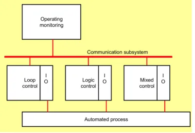
As illustrated in Figure 1, the essential backbone of such systems is the communication subsystem, which provides the mechanism for information exchange between the distributed automating devices. Connected to this backbone are the devices, such as programmable controllers, which deliver the distributed processing power of the system. Each device, under the control of its own software, performs a dedicated subtask to achieve the required overall system functionality. Each device is chosen with the size and performance required to meet the demands of its particular subtask.
In a different environment, programmable controllers are used in stand-alone applications as illustrated in Figure 2. Users of these applications also stand to gain by the evolution outlined above. Due to the present low cost of hardware components, many new, relatively small, automation tasks can be solved profitably and flexibly by programmable controllers.
Copyright International Electrotechnical Commission
Provided by IHS under license with IEC Licensee=Technip Abu Dabhi/5931917101
--``,`,`,,,``````,,``,,``,,,,`,-`-`,,`,,`,`,,`---Operating monitoring Loop control Automated process I O Logic control I O Mixed control I O I O Communication subsystem
Figure 1 – A distributed application
Operating monitoring Press Logic control I O Mixed control I O I O Pump Operating monitoring
Figure 2 – Stand-alone applications
In addition to their low hardware price, the intensive use of programmable controllers in solving automation tasks is also advanced by their straightforward operating and programming principles, which are easily understood and applied by the shop-floor personnel involved in programming, operation and maintenance.
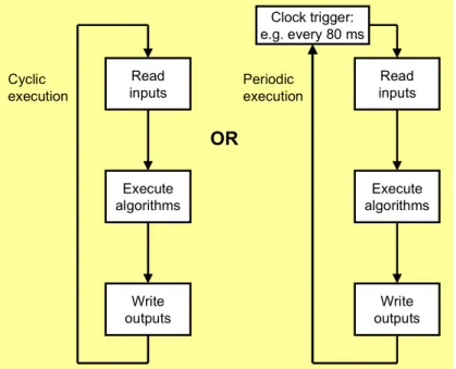
Programmable controllers typically employ the principles of cyclic or periodic program execution illustrated in Figure 3. Cyclically running programs restart execution as fast as possible after they have terminated execution. Periodic execution of a program is triggered by a clock mechanism at equidistant points in time.
These principles are well known and applied in the operation of digital signal processing systems to simulate the operation of continuously operating analog or electromechanical systems. Process values are read into the device and written out to the process as discrete samples at random or equidistant points in time, depending on the control task that has to be fulfilled.
IEC 2060/03
IEC 2061/03
Copyright International Electrotechnical Commission
Provided by IHS under license with IEC Licensee=Technip Abu Dabhi/5931917101
--``,`,`,,,``````,,``,,``,,,,`,-`-`,,`,,`,`,,`---The advantage of these operating principles is that they allow the construction of programs for programmable controllers using elements closely related to the principles of hard-wired logic or continuous control circuits previously used for the same purpose.
The operating principles of programmable controllers thus enable the provision of application-specific, graphical programming languages. Combined with appropriate man-machine inter-faces, these languages enable the control engineer to concentrate on solving the problems of the application, without extensive training in software engineering. The control engineer’s technological specifications can be mapped direct to the corresponding language elements.
Another particular advantage of such programming languages is that the representation they offer can be used not only for program input and documentation, but also for on-line test and diagnosis as well. Thus, programming support environments (PSEs) for programmable controllers are able to provide the graphically oriented representation and documentation that are already familiar to the application engineer and shop-floor personnel.
Read inputs Execute algorithms Write outputs Read inputs Execute algorithms Write outputs Cyclic execution Periodic execution
OR
Clock trigger: e.g. every 80 msFigure 3 – Cyclic or periodic scanning of a program 2.2 Overcoming historical limitations
Automation system designers are often required to use programmable controllers from various manufacturers in different automation systems, or even in the same system. However, the hardware of programmable controllers from different manufacturers may have very little in common. In the past, this has resulted in significant differences in the elements and methods of programming the software as well. This has led to the development of manufacturer-specific programming and debugging tools, which generally carried very specialized software for programming, testing and maintaining particular controller “families”.
Changing from one controller family to another often required the designer to read large manuals for both the hardware and software of the new family. Often, the manual had to be reviewed several times in order to understand the exact meaning and to use the new controller family in an appropriate way. Due to the concentrated, tedious work necessary to read and understand the new, vendor-specific material, few people did it. For this reason, many people regarded the design and the programming of such controllers as some black magic to be avoided. Thus, the knowledge of how to use such systems effectively was concentrated in one or a few specialists and could not be transferred effectively to those responsible for system operation, maintenance, and upgrade.
IEC 2062/03
Copyright International Electrotechnical Commission
Provided by IHS under license with IEC Licensee=Technip Abu Dabhi/5931917101
--``,`,`,,,``````,,``,,``,,,,`,-`-`,,`,,`,`,,`---A major goal of IEC 61131-3 was to remove such barriers to the understanding and application of programmable controllers. Thus, IEC 61131-3 introduced numerous facilities to support the advantages of programmable controllers described in 2.1, even if controllers of different vendors are concerned. It has turned out that the resulting expansion of the application domains of programmable controllers, and the increasing demand of customers fed through this expansion, stimulated a lot of vendors to make their programming systems compliant to the standard.
Vendor and user organizations like PLCopen accelerated this process by promoting the benefits and advantages of standardizing PLC programming to a large extent.
2.3 Basic features in IEC 61131-3
From the point of view of the application engineer and the control systems configurator, the most important features introduced by IEC 61131-3 can be summarized as follows.
a) Well-structured, “top-down” or “bottom-up” program development is facilitated by language constructs for the definition of typed functional objects (program organization units) such as functions, function blocks and programs.
b) Strong data typing is not only supported but inherently required, thus eliminating a major source of programming errors.
c) A sufficient set of features for the execution control of program organization units is included; those features associated with steps, transitions and action blocks offer excellent means to represent complicated sequential control solutions in a concise form.
d) The necessary functionalities for designing the communication between application programs are provided. Independent of the mapping of programs onto a single device or different devices, identical communication features can be used between two programs. This facilitates the reuse of software in different environments.
e) Two graphical languages and two textual languages may be chosen by the designer, according to the requirements of the application. These languages, plus a set of textual and graphical common elements, support software design methodologies based on well-understood models.
1) The graphical Ladder Diagram (LD) language models networks of simultaneously functioning electromechanical elements such as relay contacts and coils, timers, counters, etc.
2) The graphical Function Block Diagram (FBD) language models networks of simultaneously functioning electronic elements such as adders, multipliers, shift registers, gates, etc.
3) The Structured Text (ST) language models typical information processing tasks such as numerical algorithms using constructs found in general-purpose high level languages such as Pascal.
4) The Instruction List (IL) language models the low-level programming of control systems in assembly language.
5) A set of graphical and textual common elements provides rules for defining values and variables, features for software configuration and object declaration. The common elements include graphical and textual elements for the construction of
6) Sequential Function Charts (SFCs), which model time- and event-driven sequential control devices and algorithms.
f) Flexibility in the selection of languages suited for programming application-specific functionalities will increase the reuse of software solutions to process control problems. g) Each application specialist on a project team can use a programming style and language
suited for the particular functionality in question, with the assurance that the results of the work of the individual specialists will integrate smoothly together.
In summary, the principal goal of IEC 61131-3 is to introduce all the necessary standardized language concepts and constructs to solve the technological problems of each application and to provide principles for the construction of vendor-independent software elements. This
Copyright International Electrotechnical Commission
Provided by IHS under license with IEC Licensee=Technip Abu Dabhi/5931917101
--``,`,`,,,``````,,``,,``,,,,`,-`-`,,`,,`,`,,`---facilitates the reusability of control software designs for different controller types, even though some effort will almost always be required in order to move control programs from one controller family to another.
2.4 New features in the second edition of IEC 61131-3
Since 1993, the publication date of the first edition of IEC 61131-3, its environment has changed greatly. During the first phase, a large amount of experience with the practical application of the standard was gained. A number of inconsistencies, contradictions and unresolved questions as well as features, which were unnecessarily difficult to implement, were discovered. The industrial end-users, often represented by software companies, supplied many proposals for changes and amendments.
To maintain the value of investment by the former IEC 61131 users and by today’s users of IEC 61131-3 control software as far as possible for the future, the IEC has decided to use the review of existing standards, which is due every five years, for a two-step revision.
Step 1: Elimination of inconsistencies within IEC 61131-3 (corrigendum)
Step 2: Amelioration of specific items in need of improvement within IEC 61131-3 and the integration of features regarded as particularly relevant in practice (amendment). For every individual item to be altered, changes were kept upward-compatible, i.e. a user program compliant with the first edition is also compliant with the new edition, with the exceptions noted in Clause A.4.
A summary of the corrections and amendments is given in Annex A of this technical report.
2.5 Software engineering considerations
2.5.1 Application of software engineering principles 2.5.1.1 Encapsulation and hiding
A number of software engineering principles were employed in the development of IEC 61131-3 in order to promote increased software quality. A few of the more important principles, their contributions to software quality, and their embodiment in IEC 61131-3 are discussed below.
NOTE See Annex B of this technical report for descriptions of the software engineering quality measures referenced in this subclause, for example, reliability, maintainability, etc.
Encapsulation is the “packaging” of functionally related data and/or procedures in a single software entity. Encapsulation contributes to software reliability, maintainability, usability, and adaptability.
Associated with encapsulation is the notion of hiding of procedures and data, in which the only knowledge that the user has of a software entity is its external interface and specified functionality. Details of internal data structure and procedure implementation are intentionally hidden. Hiding contributes to software maintainability, integrity, usability, portability and reusability.
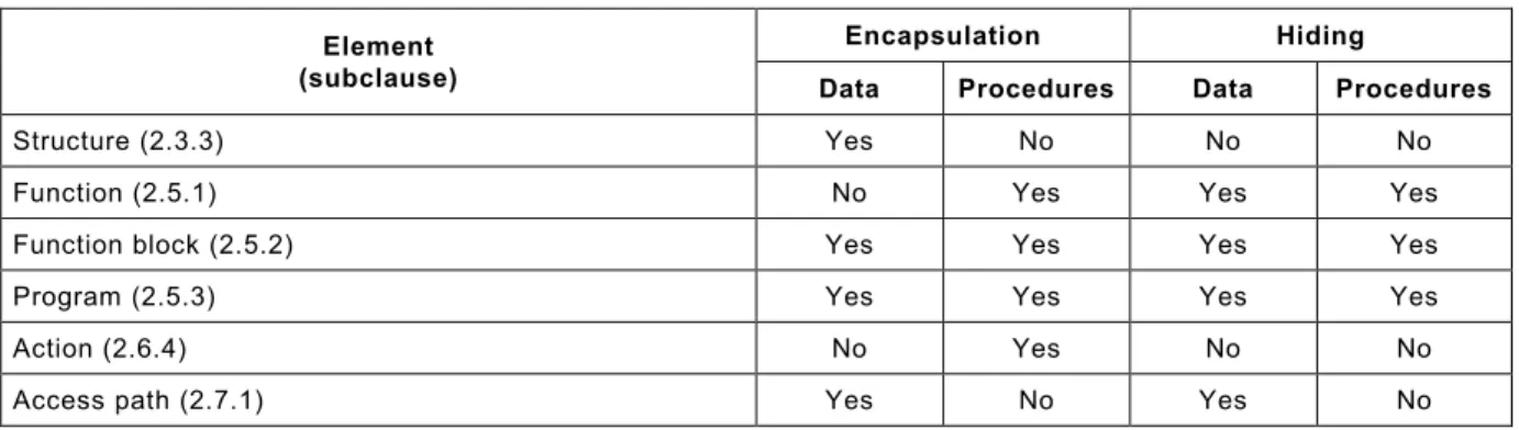
The elements of IEC 61131-3 that support encapsulation and hiding, and their main subclauses in IEC 61131-3, are listed in Table 1.
Copyright International Electrotechnical Commission
Provided by IHS under license with IEC Licensee=Technip Abu Dabhi/5931917101
--``,`,`,,,``````,,``,,``,,,,`,-`-`,,`,,`,`,,`---Table 1 – IEC 61131-3 elements supporting encapsulation and hiding Encapsulation Hiding Element
(subclause) Data Procedures Data Procedures
Structure (2.3.3) Yes No No No
Function (2.5.1) No Yes Yes Yes
Function block (2.5.2) Yes Yes Yes Yes
Program (2.5.3) Yes Yes Yes Yes
Action (2.6.4) No Yes No No
Access path (2.7.1) Yes No Yes No
2.5.1.2 Explicit representation of state
The SFC elements defined in 2.6 of IEC 61131-3 enable the state of the control system to be determined at any point in time as the set of active steps and actions. Without this representation, the state of the system must be inferred from data such as system inputs, outputs, and some set of “state” (Boolean) variables. The use of SFC elements thus contributes to software maintainability, usability and portability. Furthermore, system responsiveness and processing capacity are enhanced by performing only those portions of the software algorithm relevant to the current state.
2.5.1.3 Mapping to the application domain
The direct mapping of the elements of IEC 61131-3 to well-understood concepts in industrial-process measurement, automation and control has already been noted in 2.1 and 2.3 of this technical report. This characteristic contributes to software maintainability, usability and adaptability.
2.5.1.4 Mapping of design to implementation
IEC 61131-3 supports a style of system realization known as “top-down design” (or “design by functional decomposition”) followed by “bottom-up implementation“ (or “implementation by functional composition”). This contributes to software reliability, maintainability, usability and adaptability.
This style of system design and implementation is characterized by the following sequence of steps.
a) The desired functionality and external interface of the system are specified. For instance, the basic functionality of a machining cell might be to accept a rough part from a material handling system, produce a finished part from the rough blank, measure the finished part, pass it back to the material handling system, and report the results of the operation to a manufacturing information system. External interfaces in this cell would include the material handling and information system interfaces. The configuration elements described in 2.7 of IEC 61131-3 can be used in this step.
b) A first decomposition of the system design is made by allocating the required functionality into one or more elements, typically programs (2.5.3 of IEC 61131-3). The interfaces among the programs, and between the programs and the external interfaces of the system, are defined, and the functionality allocated to each program is defined. Such a decomposition will often follow the physical partitioning of the system; for instance, in the machining cell described above, separate programs might be defined for the machining station, the measuring station, and for the material handling robot of the cell, if any.
c) Each element defined in the preceding step is further decomposed into more basic functional units. If the functionality of the element is essentially sequential, the first step in the decomposition may be the formulation of an SFC (2.6 of IEC 61131-3) expressing the sequence of operations to be performed and the conditions for repeating the cycle of operations. Each action (2.6.4 of IEC 61131-3) of the SFC is then further decomposed,
Copyright International Electrotechnical Commission
Provided by IHS under license with IEC Licensee=Technip Abu Dabhi/5931917101
--``,`,`,,,``````,,``,,``,,,,`,-`-`,,`,,`,`,,`---typically into interconnected function blocks (2.5.2 of IEC 61131-3), i.e., an FBD (4.3 of IEC 61131-3). For instance, the main program for the machining station in the cell described above may be an SFC describing the sequence of machining operations to be performed, while the actions might contain function blocks performing the required motion control functions.
d) This functional decomposition process is performed recursively until all functionality can be identified as belonging to existing library elements (see 1.4.3 of IEC 61131-3), or can be expressed algorithmically in one of the textual or graphic languages in IEC 61131-3, i.e. IL (3.2 of IEC 61131-3), ST (3.3 of IEC 61131-3), LD (4.2 of IEC 61131-3), or FBD (4.3 of IEC 61131-3).
e) The system is then implemented by “bottom-up” functional composition, i.e., by compiling and adding to the library the newly defined elements in the reverse order in which they have been defined in the preceding steps. With some attention to design for reusability, many of the new library elements may be usable in future system designs.
f) Finally, the allocation of programs to resources, and resources to configurations is completed, program execution tasks are set up, and access paths are established for communication with information systems, using the configuration elements defined in 2.7 of IEC 61131-3.
2.5.1.5 Structured programming
The contribution of structured programming techniques to software reliability, maintainability and adaptability is well known. The ST language defined in 3.3 of IEC 61131-3 provides a full set of constructs to support this style of programming, while retaining full compatibility with the other graphical and textual languages and elements in IEC 61131-3. Whereas the first edition of IEC 61131-3 still contained deficiencies concerning this compatibility (for example, EN/ENO usage), the second edition introduces the necessary extensions and adaptations in the syntax and semantics of function calls and function block invocations, to ensure mutual language interchange.
2.5.1.6 Software reuse
The programming model described in 1.4.3 of IEC 61131-3 and shown in Figure 3 of IEC 61131-3 strongly supports the reuse of software elements. These may be developed by the user in the “bottom-up” implementation process described in 2.5.2.4 above or may be supplied as “libraries” by software vendors. This method of system construction may be unfamiliar to users who have previously developed automation system applications as a single, large ladder diagram. Hence, some training may be required in order to realize the large potential gains in software quality and productivity presented by the new approach to software reuse presented in IEC 61131-3.
As described in 1.4.3 of IEC 61131-3 and Clause B.0 of IEC 61131-3, the software elements that may be placed in libraries for reuse include, in order of increasing complexity and functionality: – data types; – functions; – function blocks; – programs; – configurations. 2.5.2 Portability 2.5.2.1 Inter-language portability
As noted in Annex B of this technical report, portability is defined as the ease with which system functionality can be moved from one system to another. This may be considered from the point of view of
Copyright International Electrotechnical Commission
Provided by IHS under license with IEC Licensee=Technip Abu Dabhi/5931917101
--``,`,`,,,``````,,``,,``,,,,`,-`-`,,`,,`,`,,`---– inter-language portability, i.e. the ease of converting a program organization unit type specification from one language to another; or
– inter-system portability, i.e. the ease of converting a program organization unit type specification from one programming support environment (PSE) to another.
As noted in 2.5.2.1 of this technical report, the encapsulation and hiding facilities of IEC 61131-3 provide a high degree of reusability of functions, function blocks, and data types among all the defined languages. However, as noted in item 5) of 2.3 of this technical report, each of the IEC 61131-3 languages is specialized to some extent for a particular model of the problem domain. This limits the ease with which an algorithm written in one of the IEC languages can be translated into another programming language. For instance,
– the selection and iteration constructs of the ST language are difficult to translate efficiently into FBD or LD;
– textual expressions can only be used in the ST language, not in the LD or FBD language. The problems in the first edition of IEC 61131-3 with the different support of EN/ENO in graphical languages and textual languages are solved in the second edition, as already mentioned in 2.5.1.5.
Due to the remaining limitations, the user should choose the language most appropriate to the type of algorithm to be developed in the body of a function or function block.
2.5.2.2 Inter-system portability
IEC 61131-3 neither defines nor requires a common exchange format for interchange of program organization unit (POU) type definitions written in graphical languages; but it does specify a textual syntax in its Annex B for the common elements and for the two textual languages ST and IL. The minimally required encoding for the export and import of library elements written in this textual format is also defined in item j) of 1.5.1 of IEC 61131-3. This is a new requirement in the second edition of IEC 61131-3, which will improve inter-system portability.
Consequently, compliant POUs, as defined in 1.5.2 of IEC 61131-3, may only be portable if they are written in a textual language (ST or IL). Even if written in textual language, compliant POUs will not be portable unless the set of features supported in the target system is equal to or a superset of the features supported in the source system. Compliant POUs may also not be portable if the set of implementation-dependent parameters of the two systems differ in important values. A typical example is the support of a different number of characters used in distinguishing two identifiers.
3 Application guidelines 3.1 Use of data types
Subclause 2.3.2 of IEC 61131-3 offers many elementary data types. The user can also define new data types, as described in 2.3.3 of IEC 61131-3, as necessary to meet the data representation needs of the application. All data types, including user-defined types, are made available for use in a “library” of data types as described in 1.4.3 of IEC 61131-3. The user then declares the data type to be used for each variable.
The selection of a type for a variable should be appropriate to the range of values and operations to be performed on the variable. For instance,
– if a variable can only hold the values 0 or 1, and is only to be operated on by Boolean
operations, then the elementary type BOOL should be chosen;
– if a programmable controller program has to count something and the counts are expected to be in the range from 0 to 1000, a variable of type SINT or USINT cannot be used, since
Copyright International Electrotechnical Commission
Provided by IHS under license with IEC Licensee=Technip Abu Dabhi/5931917101
--``,`,`,,,``````,,``,,``,,,,`,-`-`,,`,,`,`,,`---their value ranges only extend from -128 to +127 for SINT and from 0 to 255 for USINT.
A reasonable data type for this purpose would be UINT. This has a sufficient value range
and the usage of an unsigned integer type also makes it clear that negative values are not expected.
3.1.1 Type versus variable initialization
In a program that complies with IEC 61131-3, each variable has to be initialized, either explicitly by programming or implicitly by the default mechanisms defined in the standard. Uninitialized values should never occur. To ease the declaration of variables, all elementary types have default initial values specified in the standard. If no initialization of a variable is specified by the user, then that variable will have the default initial value. Most default initial values are defined as the representation of the value of zero for the type.
IEC 61131-3 also allows the user to specify default initial values for user-defined types. For instance, consider a type declared by
TYPE TempLimit : REAL:= 250.0; END_TYPE
Any declared variable of this new type TempLimit is initialized with the default value of 250.0
instead of 0.0 as would be the normal case for all REAL data. Thus, in the following declaration,
the variable BoilerMaxTemperature is initialized to 250.0, while the variable PipeMaxTemperature is initialized to 0.0. If the value of zero is not a reasonable maximum
temperature for the pipeline, its correct value has to be set before the first usage of the variable. Forgetting this will cause problems. In the present example, the maximum temperature for the boiler is initialized with a proper default initial value. There is no need for a set-up before the first usage, which greatly simplifies a programmable controller program and increases software reliability.
VAR_GLOBAL
BoilerMaxTemperature: TempLimit; PipeMaxTemperature: REAL;
END_VAR
3.1.2 Use of enumerated and subrange types
IEC 61131-3 provides mechanisms for the definition of enumerated and subrange types. These types can make a program more readable and thus act as documentation aids. In addition, these types can contribute to program reliability by helping to avoid the use of unintended values of variables as well as by explicitly expressing the intended semantics of the values of enumerated variables.
An enumerated data type restricts the values of variables of the type to a user-defined set of identifiers. As an example consider
TYPE Color : ( Red, Yellow, Green ); END_TYPE ...
VAR_GLOBAL brickColor : Color; END_VAR
Here a new type Color is defined. It may only have three values – Red, Green, or Blue.
IEC 61131-3 does not define numerical values to which these enumerated values may correspond. There also is no conversion function to and from enumerated types to integral types. The values only have to be distinct and reproducible. An assignment of a value to the variable brickColor is possible only if one of the defined colour values is used. All other
values are flagged as errors.
IEC 61131-3 provides standard functions for multiplexing, selection, and comparison (equality and inequality) of enumerated data types.
IEC 61131-3, 2nd edition, also provides for the typing of enumerated values to distinguish, for instance, between the values brickColor#Red and paintColor#Red. The second edition also
allows the use of an enumerated value as a selector in a CASE statement.
Copyright International Electrotechnical Commission
Provided by IHS under license with IEC Licensee=Technip Abu Dabhi/5931917101
--``,`,`,,,``````,,``,,``,,,,`,-`-`,,`,,`,`,,`---The syntax given in B.1.4 and B.1.3.3 of IEC 61131-3 allows the creation of “anonymous subrange data types” and “anonymous enumerated data types” in the declaration of variables and of elements of structured data types. An “anonymous subrange data type” is characterized by its base type and subrange. Similarly, an “anonymous enumerated data type” is characterized by the number, order, and identifiers of its enumerated values.
EXAMPLE 1
Given the type and variable declarations below, the variable Y is considered to be of the same
anonymous enumerated type as the CURRENT_COLOR component of the variable X and the
assignment statement shown is valid. However, an assignment of the value of the variable
brickColor shown above to either Y or X.CURRENT_COLOR is not allowed because the type Color is not anonymous.
TYPE TRAFFIC_LIGHT: STRUCT
POWER_STATE: BOOL;
CURRENT_COLOR: (Red, Yellow, Green); END_STRUCT
END_TYPE
VAR X: TRAFFIC_LIGHT; Y: (Red, Yellow, Green); END_VAR
...
Y := X.CURRENT_COLOR;
EXAMPLE 2
See 3.1.9 below for an example of the definition and use of an “anonymous subrange type”.
3.1.3 Use of BCD data
Users should be aware of the fact that “BCD” is not a data type in IEC 61131-3. Rather, it represents an encoding option for the bit-string types BYTE, WORD, DWORD, and LWORD, where data of these types might be encoded as 2, 4, 8, or 16 BCD digits, respectively. This is in recognition of the fact that BCD is rarely used in modern systems except for transfer of data in bit-string form to and from external devices such as multi-segment displays and thumbwheel switches.
Since compliant systems are not required to support BCD arithmetic, BCD encoded data must be converted to one of the integer types (SINT, INT, DINT, LINT, USINT, UINT, UDINT, or ULINT) using one of the BCD_TO_** conversion functions defined in 2.5.1.5.2 of IEC 61131-3, in order to be manipulated arithmetically. Similarly, the **_TO_BCD functions are provided to convert integer data to BCD encoded form for transfer to external devices.
Users should be aware of the potential errors that may be caused in the encoding of BCD data. a) Since no standard BCD encoding is defined for the “minus” sign, the use of a negative
number as an input to a **_TO_BCD conversion may cause a conversion error.
b) The range of an integer variable is larger than the range of a BCD-encoded bit string variable with the same number of bits. For instance, the range of a variable of type SINT is (–128..127), while the range of numbers that can be encoded in a bit string of type BYTE is only (0..99).
The example shown in Figure 4 illustrates precautions that may be necessary to avoid these errors. In this example, the function block BCD_DIFF takes the difference between two two-digit BCD-encoded inputs THUMB1 and THUMB2 and outputs the result as a two-two-digit BCD encoded bit string plus a Boolean sign, which could be used for example to drive a “two-digit plus sign” BCD display.
Copyright International Electrotechnical Commission
Provided by IHS under license with IEC Licensee=Technip Abu Dabhi/5931917101
--``,`,`,,,``````,,``,,``,,,,`,-`-`,,`,,`,`,,`---+---+ | BCD_DIFF |
BYTE---|THUMB1 SGN|---BYTE
BYTE---|THUMB2 DIFF|---BYTE +---+
Figure 4a −−−− External interface
+---+ +----| < |---SGN | +--| | | | +---+ | | +---+ | | +---+ +---+ +---+
THUMB1--| BCD_TO_SINT |-+-|--| - |--| ABS |--| SINT_ |--DIFF
+---+ +--| | +---+ | TO_ | | +---+ | BCD | +---+ | +---+ THUMB2--| BCD_TO_SINT |---+ +---+ Figure 4b −−−− Body
Figure 4 – Function block BCD_DIFF
A different solution to this problem would be to define a new structured data type containing both the sign and BCD-encoded data, such as type SBCD_BYTE shown in Figure 5a. Functions such as SBCD_DIFF, as shown in Figure 5b and c, could then be defined which produce values of this new type as the result of their execution.
TYPE SBCD_BYTE: STRUCT DATA: BYTE; SGN: BOOL; END_STRUCT; END_TYPE
Figure 5a −−−− Definition of structured data type SBCD_BYTE
+---+ | SBCD_DIFF |
BYTE---|THUMB1 |---SBCD_BYTE
BYTE---|THUMB2 |
+---+
Figure 5b −−−− External interface
+---+ +----| < |---SBCD_DIFF.SGN | +--| | | | +---+ | | +---+ | | +---+ +---+ +---+
THUMB1--| BCD_TO_SINT |-+-|--| - |--| ABS |--| SINT_ |--SBCD_DIFF.DATA
+---+ +--| | +---+ | TO_ | | +---+ | BCD | +---+ | +---+ THUMB2--| BCD_TO_SINT |---+ +---+ Figure 5c −−−− Body
Figure 5 – Function block SBCD_DIFFF 3.1.4 Use of REAL data types
The 32-bit REAL data type described in 2.3.1 of IEC 61131-3 can be used for holding the
majority of decimal values such as control loop set-points, and process values. The REAL data
type supports a wide range of values within the range ±10±38 , with a precision of 1 part in 223,
i.e., 1 part in 8388608.
IEC 2064/03
Copyright International Electrotechnical Commission
Provided by IHS under license with IEC Licensee=Technip Abu Dabhi/5931917101
--``,`,`,,,``````,,``,,``,,,,`,-`-`,,`,,`,`,,`---Where a higher value range or higher precision is required, the 64-bit (long) format LREAL can
be used with a range of ±10±308 and precision of 1 part in 252.
NOTE 1 In some algorithms, rounding errors may be magnified by the calculations performed. Data types with higher precision than initially apparent may be required in order to avoid such errors.
NOTE 2 See 4.2.1 of this technical report for additional considerations in the implementation of REAL types.
3.1.5 Use of character string data types
The STRING data type provides storage for variable length textual data consisting of 8-bit
characters, which is required in the majority of application programs, for example, for holding process batch identifiers, recipe names, operator security codes.
IEC 61131-3, second edition, also provides the WSTRING data type for strings of 16-bit
(“Unicode”) characters.
IEC 61131-3 provides means for defining non-printable characters within a character string. This is often required when constructing messages for external devices. For example, in order to format a report it may be necessary to embed “form feed” and similar control characters in messages sent to a printer.
Length of character strings
According to IEC 61131-3, a character string is characterized by its maximum length and its current length. The maximum length is determined by the declaration of a string variable or the usage of a string constant.
• Implementation-dependent maximum length, Lmi
• Implementation-dependent default length, Ldi ≤ Lmi
• Declared maximum length, Lmd ≤ Lmi
– Lmd = Ldi when length is not explicitly declared for string variables – Lmd = Actual string length for string constants
The current length of a string constant does not change, but the current length of a string variable may be changed by an assignment of a new value to the string.
• Current length, Lc
– Lc ≤ Lmd for string variables – Lc = Lmd for string constants
IEC 61131-3 does not specify what may happen when an assignment operation tries to assign a new value of current length Lc,new to a string variable with declared maximum length Lmd <
Lc,new. Users should be aware that implementation dependencies may cause an error or may truncate the assigned value to the length Lmd in this case.
NOTE Truncation rather than error is the recommended option for implementers.
Copyright International Electrotechnical Commission
Provided by IHS under license with IEC Licensee=Technip Abu Dabhi/5931917101
--``,`,`,,,``````,,``,,``,,,,`,-`-`,,`,,`,`,,`---3.1.6 Use of time data types
IEC 61131-3 provides a number of data types for holding time of day, date and duration. Recording the times activities occur, measuring process durations, and triggering actions at prescribed times of day or on particular dates are typical and, in some cases, essential features of most process, production and manufacturing application programs.
Typical usage of time includes
a) accurate definition of the duration of a process phase, for example, in heat treatment where the annealing time of some materials is critical;
b) recording the date and time of alarm conditions for process audit and maintenance purposes;
c) controlled switch-on of a process according to the time of day, for example, to initiate pre-heating of a reactor vessel before the first shift of the week;
d) recording the calibration date of critical analog inputs so that the system can warn when re-calibration is required;
e) recording the times of power failure and power resumption, to calculate the down-time duration. This can be used with an application to define a power-fail strategy. For example, if power fails for a few minutes, the application may be able to continue because the process vessels are still warm; however, after a long power failure, the application should abort the process and take whatever action is necessary to put the plant into a safe state;
NOTE 1 This example assumes that the programmable controller is able to retain the date and time of power failure in non-volatile memory.
f) defining time-outs for certain operations to complete. For example, if a communications transaction with a serial device is not complete by a certain time, the operation is assumed to have failed.
The time data types TIME, TIME_OF_DAY, DATE and DATE_AND_TIME, can be used in
expressions with the numeric operators ADD (+), SUB (-), MUL (*), DIV (/), and also with
the concatenation function CONCAT. An example of such usage is given in Figure 6.
processDuration := phaseDuration * phaseCount;
endTime := startTime + processDuration;
endDateAndTime := CONCAT_DATE_TOD(todayDate, endTime);
Figure 6 – ST example of time data type usage
There are also type conversion functions to support all the required manipulation between dates, time of day and duration. For example, it is possible to extract the TIME_OF_DAY from a DATE_AND_TIME variable.
NOTE 2 IEC 61131-3, secon edition, modified the naming conventions for several functions of time data types in Table 30 of IEC 61131-1, in order to make them consistent with the definition of overloaded functions given in 2.5.1.4 of IEC 61131-3. Previous function names not consistent with this definition are deprecated, i.e. they will not be included in IEC 61131-3, third edition.
3.1.7 Declaration and use of multi-element variables
There is provision within IEC 61131-3 for multi-element (“aggregate“) variables, including
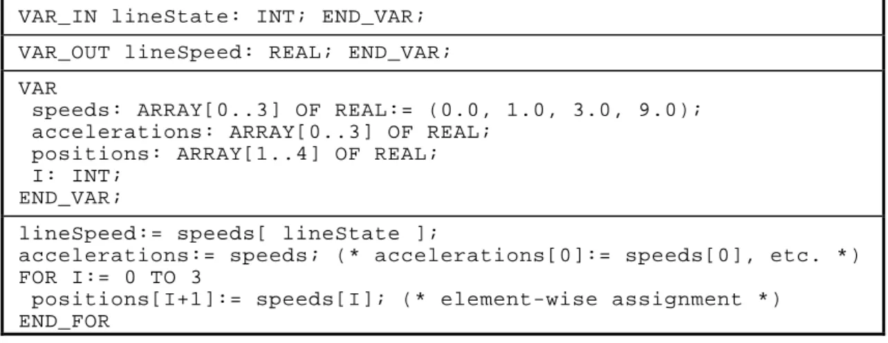
arrays and structures. Arrays are useful in a wide range of programs. Their use can avoid repetition of code and in many cases can make the program easier to understand. An example of the usage of an array variable is given in Figure 7. In this example, speeds is an array of
permitted line speeds, and lineState is an integer (INT) giving state of the line such as 0 for
stopped, 1 to 3 for graded increases in speed.
IEC 2065/03
Copyright International Electrotechnical Commission
Provided by IHS under license with IEC Licensee=Technip Abu Dabhi/5931917101
--``,`,`,,,``````,,``,,``,,,,`,-`-`,,`,,`,`,,`---According to the IEC 61131-3 definition of aggregate, each definition of an array in a variable or structure declaration creates a data type. Such “anonymous array types” are characterized by their element types and subscript range(s). For instance, the aggregate accelerations as
declared in Figure 7 would be considered to be of the same type as the aggregate speeds,
while the aggregate positions would not be considered to be of the same type. Hence the
values of all elements of the aggregate accelerations can be assigned the values of all
elements of the aggregate speeds in a single assignment, while the assignment of values from speeds to the elements of positions has to be done by component-wise assignment as shown
in Figure 7.
VAR_IN lineState: INT; END_VAR; VAR_OUT lineSpeed: REAL; END_VAR; VAR
speeds: ARRAY[0..3] OF REAL:= (0.0, 1.0, 3.0, 9.0); accelerations: ARRAY[0..3] OF REAL;
positions: ARRAY[1..4] OF REAL; I: INT;
END_VAR;
lineSpeed:= speeds[ lineState ];
accelerations:= speeds; (* accelerations[0]:= speeds[0], etc. *) FOR I:= 0 TO 3
positions[I+1]:= speeds[I]; (* element-wise assignment *) END_FOR
Figure 7 – Example of declaration and use of “anonymous array types” 3.1.8 Use of bit-string functions
The selection and comparison functions in Tables 27 and 28 of IEC 61131-3 are defined to operate on data of the bit-string data types BOOL, BYTE, WORD, DWORD and LWORD as well as
on numeric data types such as INT. Comparisons of bit-string data are made bitwise from the
most significant to the least significant bit, and shorter bit strings are considered to be filled on the left with zeros when compared to longer bit strings; that is, comparison of bit-string variables has the same result as comparison of unsigned integer variables.
EXAMPLES – The following expressions all evaluate to TRUE:
GT(TRUE,FALSE) GT(TRUE, DWORD#0) GT(WORD#1FF, BYTE#FF)
The operation of MIN and MAX functions on bit-string types can be considered as an application of the comparison functions. For mathematical details, see 4.2.2.
EXAMPLES
MAX(BYTE#5, BYTE#F0, BYTE#EF) = BYTE#F0 because
BYTE#F0 ≥ BYTE#5 and BYTE#F0 ≥ BYTE#EF;
similarly,
MIN(BYTE#5, BYTE#F0, BYTE#EF) = BYTE#5 because
BYTE#5 ≤ BYTE#F0 and BYTE#5 ≤ BYTE#EF .
IEC 2066/03
Copyright International Electrotechnical Commission
Provided by IHS under license with IEC Licensee=Technip Abu Dabhi/5931917101
--``,`,`,,,``````,,``,,``,,,,`,-`-`,,`,,`,`,,`---3.1.9 Strongly typed assignment
Although not explicitly stated in IEC 61131-3, it was the intention of the standard to specify that assignment of the result of evaluating an expression to a variable be “strongly typed”; that is, that assignment should only take place when the result is of the same type as the variable. This is implied, for instance, by the discussion of the assignment statement in 3.3.2.1 of IEC 61131-3. In this interpretation, a result is considered to be of the same type as a variable when
– its type name is the same as the type name of the variable to which it is to be assigned; or – both the result and the variable to which it is to be assigned are “anonymous array types”
as discussed in 3.1.7, whose element type and subscript range(s) exactly match each other; or
– both the result and the variable to which it is to be assigned are “anonymous enumerated types” as discussed in 3.1.2 , whose enumerated value sets exactly match each other in number, order and identifiers of the enumeration elements.
In contrast, the assignment of a result to the value of a variable is allowed as long as the type of the result is the same as the “parent” type of the subrange type of the variable; however, a run-time check must be made to determine that the value is within the specified subrange limits of the variable.
These conditions apply not only to the assignment of values to variables in assignment statements but also to the use of the ST (store) operator in the IL language defined in 3.2.2
of EC 61131-3, data flow connections in the LD and FBD languages defined in Clause 4 of IEC 61131-3, and data passing as discussed in 3.2.
EXAMPLE 1
Consider the variables defined in the statements
VAR X : ARRAY[1..16] OF ANALOG_CHANNEL_CONFIGURATION; (* A variable of an anonymous array type *) Y : ANALOG_16_INPUT_CONFIGURATION;
Z : SINT(5..95) ; (* A variable of an anonymous subrange type *) END_VAR
Where the applicable data types are defined as in Table 12 of IEC 61131-3:
TYPE ANALOG_CHANNEL_CONFIGURATION : STRUCT RANGE : ANALOG_SIGNAL_RANGE ; MIN_SCALE : ANALOG_DATA ; MAX_SCALE : ANALOG_DATA ; END_STRUCT ; ANALOG_16_INPUT_CONFIGURATION : STRUCT SIGNAL_TYPE : ANALOG_SIGNAL_TYPE ; FILTER_PARAMETER : SINT (0..99) ;
(* An anonymous subrange data type *)
CHANNEL : ARRAY [1..16] OF ANALOG_CHANNEL_CONFIGURATION; (* An anonymous array type *)
END_STRUCT ; END_TYPE
Then an assignment statement of the form
X:= Y.CHANNEL;
is valid and would cause an assignment of the values Y.CHANNEL[1] through Y.CHANNEL[16]
to the variable elements X[1] through X[16], respectively.
Copyright International Electrotechnical Commission
Provided by IHS under license with IEC Licensee=Technip Abu Dabhi/5931917101
--``,`,`,,,``````,,``,,``,,,,`,-`-`,,`,,`,`,,`---Similarly, an assignment statement of the form
Z := Y.FILTER_PARAMETER;
is valid and could cause an assignment of the value of the FILTER_PARAMETER element of the
structured variable Y to the variable Z. However, a run-time error would occur if the value of the FILTER_PARAMETER element were less than 5 or greater than 95.
EXAMPLE 2
See 3.1.2 for an example and use of an “anonymous enumerated type”.
3.2 Data passing
There are several methods for passing data into and out of POUs including functions, function blocks, and programs.
NOTE 1 The term “parameter passing” is not used in this subclause, because the term parameter is not used in IEC 61131-3 except in the narrow sense of “A variable that is given a constant value for a specified application and that may denote the application” as defined in ISO/IEC 2382-02 and cited in IEC 61499-1. Therefore, the term parameter is only used in IEC 61131-3 in the context of “implementation-dependent parameters” and “configuration parameters”. The term variable is used instead in all other contexts to mean “A software entity that may take different values, one at a time” as defined in IEC 61499-1.
The most restricted methods to access data are defined for functions. Inside functions, only reading of input variables is allowed and a function has to return a value which may be of an aggregate type (for example, array, string or structure). Functions do not have any access to globally defined variables, nor may they access directly represented variables. As another design goal the standard requires functions to have no static variables. This means a function cannot save any of its computed or input values from one invocation to the next. Each invocation will receive a set of freshly initialized local variables, possibly with default values if not stated differently by the function definition. These restrictions ensure that operation of the function is independent of any previous execution, depending only on the set of argument values from its current invocation.
NOTE 2 IEC 61131-3, second edition, now allows functions to access in-out variables (see 3.2.2 ), and output variables in addition to input and internal variables and the single variable denoting the function output.
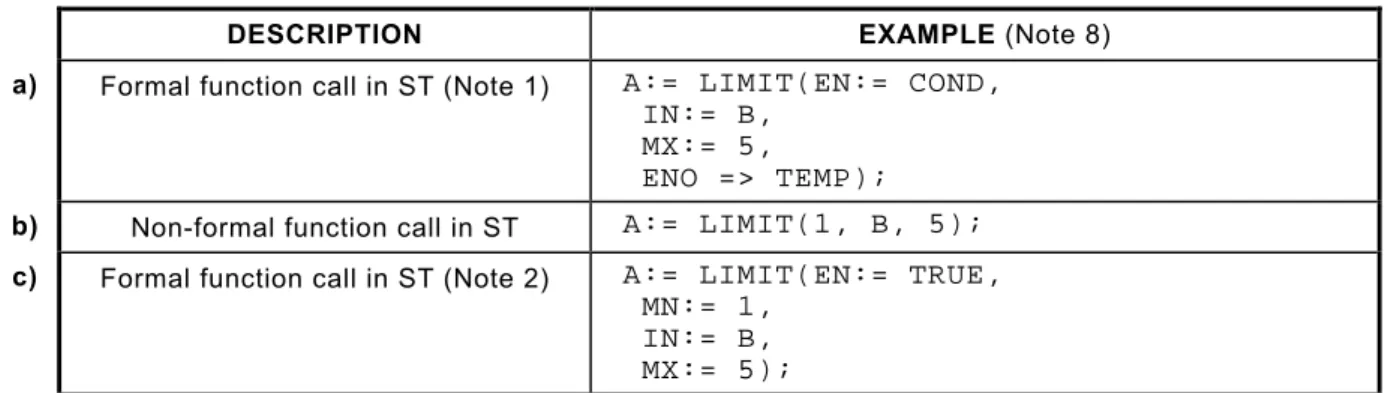
NOTE 3 IEC 61131-3, second edition, has also introduced additional flexibility in the means for textual invocations of functions; see 2.5.1.1 of IEC 61131-3 and 3.2.3 .
Within a function block body, the reading of input variables and reading or writing of output variables is permitted. Function blocks also may have in-out variables, which can be read or written. All global variables that were defined within a configuration, resource, or program by use of the VAR_GLOBAL keyword can be accessed from the inside of the function block, if
these global variables are redeclared in the function block definition by use of the
VAR_EXTERNAL keyword.
NOTE 4 IEC 61131-3, second edition, now allows function blocks in addition to programs, configurations and resources to access directly represented variables.
The values of directly represented variables can be passed to a function block as input variables from the program outside that function block. The same holds for output values from a function block, which can be copied to directly represented variables in a program. A function block may declare static storage that it can use to save any data from one invocation to the next. Function block execution can therefore have many effects upon data, including external data, which may be essential to the operation of the function block.
Programs have access to data as function blocks have and can contain declarations of global variables and access paths; see 2.5.3 of IEC 61131-3. These have to be declared within the program and thereafter can be freely read or written.
3.2.1 Global and external variables
Global variables can be defined and initialized within a configuration, resource, or program by use of the VAR_GLOBAL keyword. Each program or function block that needs access to one or
Copyright International Electrotechnical Commission
Provided by IHS under license with IEC Licensee=Technip Abu Dabhi/5931917101