ISTANBUL TECHNICAL UNIVERSITYFGRADUATE SCHOOL OF SCIENCE ENGINEERING AND TECHNOLOGY
PHYSICAL LAYER IMPAIRMENTS AWARE DYNAMIC LIGHTPATH PROVISIONING IN MIXED LINE RATE WDM NETWORKS
Ph.D. THESIS Haydar ÇUKURTEPE
Department of Computer Engineering Computer Engineering Programme
ISTANBUL TECHNICAL UNIVERSITYFGRADUATE SCHOOL OF SCIENCE ENGINEERING AND TECHNOLOGY
PHYSICAL LAYER IMPAIRMENTS AWARE DYNAMIC LIGHTPATH PROVISIONING IN MIXED LINE RATE WDM NETWORKS
Ph.D. THESIS Haydar ÇUKURTEPE
(504052507)
Department of Computer Engineering Computer Engineering Programme
Thesis Advisor: Assoc. Prof. Dr. Ay¸segül YAYIMLI Thesis Co-advisor: Prof. Dr. Biswanath MUKHERJEE
˙ISTANBUL TEKN˙IK ÜN˙IVERS˙ITES˙IFFEN B˙IL˙IMLER˙I ENST˙ITÜSÜ
F˙IZ˙IKSEL KATMAN BOZUCU ETK˙ILER˙I GÖZET˙ILEREK
ÇOKLU VER˙I ˙ILET˙IM HIZLI DALGABOYU BÖLÜMLEMEL˙I ÇO ˘GULLAMA A ˘GLARINDA D˙INAM˙IK I ¸SIKYOLU KURULUMU
DOKTORA TEZ˙I Haydar ÇUKURTEPE
(504052507)
Bilgisayar Mühendisli˘gi Anabilim Dalı Bilgisayar Mühendisli˘gi Doktora Programı
Tez Danı¸smanı: Doç. Dr. Ay¸segül YAYIMLI Tez E¸sdanı¸smanı: Prof. Dr. Biswanath MUKHERJEE
Haydar ÇUKURTEPE, a Ph.D. student of ITU Graduate School of Science Engineer-ing and Technology 504052507 successfully defended the thesis entitled“PHYSICAL LAYER IMPAIRMENTS AWARE DYNAMIC LIGHTPATH PROVISIONING IN MIXED LINE RATE WDM NETWORKS”, which he/she prepared after ful-filling the requirements specified in the associated legislations, before the jury whose signatures are below.
Thesis Advisor : Assoc. Prof. Dr. Ay¸segül YAYIMLI ... Istanbul Technical University
Co-advisor : Prof. Dr. Biswanath MUKHERJEE ... University of California, DAVIS, USA
Jury Members : Prof. Dr. Ali Emre HARMANCI ... Istanbul Technical University
Prof. Dr. Bülent ÖRENC˙IK ... Istanbul Technical University
Prof. Dr. Sema OKTU ˘G ... Istanbul Technical University
Prof. Dr. Fatih ALAGÖZ ... Bo˘gaziçi University
Asst. Prof. Dr. Fatma CORUT ERG˙IN ... Marmara University
Date of Submission : 29 November 2013 Date of Defense : 27 January 2014
FOREWORD
There had been many late nights and early mornings, and after all the work, it is a great pleasure to conclude that the thesis is over. I am really honored to be writing these lines.
Through the rough road of this thesis, I have been personally blessed with family, friends, mentors, and colleagues, who had so generously given their times as well as intellectual, spiritual, and emotional support. There are many people to whom I am eternally grateful.
First and foremost, I would like to thank my advisor, Assoc. Prof. Dr. Ay¸segül YAYIMLI. You have been supportive since the first day I began. You not only guided my researches, but also encouraged me to keep studying when I was at the verge of give up.
I would like to express my deep gratitude to Prof. Dr. MUKHERJEE, my co-advisor. Thanks Bis, for your useful critiques, enthusiastic encouragement, and patient guidance. I am really honored and lucky to know and work with you.
I would like to thank my committee members who were more than generous with their expertise and precious time. Thanks Prof. Dr. Ali Emre HARMANCI and Prof. Dr. Bülent ÖRENC˙IK for your countless hours of reading, encouraging, and your guidence.
I would like to offer my special thanks to Assoc. Prof. Massimo TORNATORE. I couldn’t have done it without your guidance and help.
I would like to thank to my friends and colleagues at computer engineering department at Istanbul Technical University, and to my friends and colleagues at Networks Lab in University of California, Davis, USA.
I would like to thank to The Scientific and Technological Research Council of Turkey (TUBITAK) for their support.
And finally, I would like to thank my family. Thank you for being indulgent when I spend time studying, which I should have spend with you. Özlem, thank you for supporting me, and at times, being a single-parent to our daughter. I hope you know that I couldn’t have done this without your tremendous help.
TABLE OF CONTENTS Page FOREWORD... ix TABLE OF CONTENTS... xi ABBREVIATIONS ... xiii LIST OF TABLES ... xv
LIST OF FIGURES ...xvii
SUMMARY ... xix ÖZET ...xxiii 1. INTRODUCTION ... 1 2. OPTICAL WDM TRANSMISSION ... 5 2.1 Introduction ... 5 2.1.1 Transmission of a signal ... 7 2.1.2 Modulation ... 9
2.2 Physical Layer Impairments (PLI) ... 11
2.2.1 Linear impairments... 11
2.2.2 Non-linear impairments... 16
2.3 Quality of Transmission (QoT) ... 18
2.3.1 Optical signal-to-noise ratio (OSNR) ... 19
2.3.2 Bit-error rate (BER) estimation ... 20
3. IMPAIRMENT-AWARE LIGHTPATH PROVISIONING IN MLR NETWORKS ... 25
3.1 Introduction ... 25
3.2 Related Works... 26
3.3 Problem Definition ... 28
4. INVERSE MULTIPLEXING BASED LIGHTPATH PROVISIONING ALGORITHMS ... 31
4.1 Algorithms ... 32
4.1.1 Path selection schemes ... 32
4.1.2 Wavelength assignment schemes... 33
4.2 Illustrative Numerical Examples ... 34
4.3 Conclusion ... 41
5. DYNAMIC LIGHTPATH PROVISIONING ALGORITHMS ... 43
5.1 Fixed Wavelength-Interval Allocation (FWIA)... 43
5.2 Weighted Routing and Wavelength Assignment (W-RWA) ... 45
5.2.1 Auxiliary graph construction ... 45
5.2.2 Weight assignment... 45
5.2.3 Algorithm ... 48
5.4 Conclusion ... 56
6. LAUNCH POWER DETERMINATION... 57
6.1 Introduction ... 57
6.2 Related Works... 58
6.3 Effects of Launch Power ... 59
6.4 Launch Power Determination Algorithms... 61
6.4.1 Worst-case best-case average (WBA)... 61
6.4.2 Impairment-aware launch power determination (I-ALPD) ... 63
6.5 Illustrative Numerical Examples ... 64
6.6 Conclusion ... 71
7. CONCLUSION ... 73
REFERENCES... 77
APPENDICES ... 83
APPENDIX A : System Parameters... 85
APPENDIX B : Topologies ... 87
APPENDIX C : Inverse Multiplexing Evaluation ... 89
ABBREVIATIONS
ASE :Amplified Spontanous Emission
BB :Best Bit-Error Rate
BBR :Bandwidth Blocking Ratio
BER :Bit-Error Rate
CAPEX :Capital Expenditure
CD :Chromatic Dispersion
DCF :Dispersion Compensation Fiber DeMUX :Demultiplexer
DPSK :Differential Phase Shift Keying
DQPSK :Differential Quadrature Phase Shift Keying DP-QPSK :Dual Polarization Quadrature Phase Shift Keying EDFA :Erbium Doped Fiber Amplifier
EON :European Optical Network
FBG :Fiber Bragg Grating
FF-W-GB :First-Fit Worst-Case (with) Guard Band
FWM :Four Wave Mixing
FWIA :Fixed Wavelength Interval Allocation
GB :Guard Band
IA :Impairment Aware
I-ALPD :Impairment-Aware Launch Power Determination
IM :Inverse Multiplexing
LCP :Least Congested Path
MH :Minimum Hop
MLR :Mixed Line Rate
MSD :Maximum Spectral Distance
MUX :Multiplexer
NMS :Network Management System
OEO :Optical-Electronic-Optical (Conversion)
OOK :On-Off Keying
OSNR :Optical Signal-to-Noise Ratio OXC :Optical Cross Connect
PCE :Path Computation Element PLI :Physical-Layer Impairment PMD :Polarization Mode Dispersion QoT :Quality of Transmission
ROADM :Reconfigurable Optical Add Drop Multiplexer RWA :Routing and Wavelength Assignment
SP :Shortest Path
SPM :Self-Phase Modulation
WBA : Worst-case Best-case Average WDM : Wavelength Division Multiplexing
W-RWA : Weighted Routing and Wavelength Assignment WSS : Wavelength Selective Switch
XPM : Cross-Phase Modulation
XT : Crosstalk
10G : 10 Gbps
40G : 40 Gbps
LIST OF TABLES
Page
Table 2.1 : Single and inter-channel impairments... 11
Table 4.1 : Proposed algorithms using IM. ... 32
Table 6.1 : Sample average-reach table... 63
Table 6.2 : Sample weight thresholds... 64
Table A.1 : System parameters for impairment-aware dynamic lightpath establishment problem. ... 85
LIST OF FIGURES
Page
Figure 2.1 : MLR on WDM optical networks... 5
Figure 2.2 : Different node types. ... 6
Figure 2.3 : Wavelength and frequency relation. ... 8
Figure 2.4 : Different keying techniques... 9
Figure 2.5 : Attenuation of optical signal... 12
Figure 2.6 : ASE noise production... 12
Figure 2.7 : PMD effect on channels of fiber. ... 13
Figure 2.8 : Effects of chromatic dispersion. ... 14
Figure 2.9 : Switch crosstalk types. ... 15
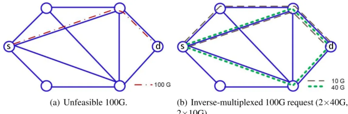
Figure 4.1 : Inverse multiplexing. ... 31
Figure 4.2 : Maximum spectral distance calculation. ... 33
Figure 4.3 : Blocking ratio due to PLIs (NSFNET topology)... 36
Figure 4.4 : Blocking ratio due to PLIs (EON topology)... 36
Figure 4.5 : Blocking ratio due to PLIs (6-node topology)... 37
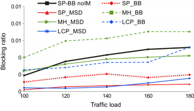
Figure 4.6 : Total (physical-layer and resource) blocking ratio results of proposed schemes for different topologies. ... 38
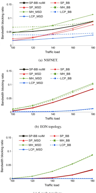
Figure 4.7 : Bandwidth blocking ratio results of proposed schemes for different topologies. ... 40
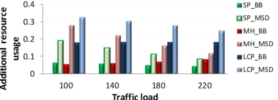
Figure 4.8 : Additional network resource (wavelength-links) usage of the proposed schemes for NSFNET... 41
Figure 4.9 : Additional resource usage at certain blocking ratio. ... 41
Figure 5.1 : Fixed Wavelength-Interval Allocation... 44
Figure 5.2 : Auxiliary graph construction. ... 46
Figure 5.3 : BBR of different schemes with (a) multiple-attempt and (b) single-attempt scenarios, for uniformly-distributed traffic. ... 52
Figure 5.4 : BBR of different schemes with multiple-attempt scenario, for skewed traffic. ... 52
Figure 5.5 : Network utilization with different schemes... 53
Figure 5.6 : Average length of established lightpaths. ... 54
Figure 5.7 : Average hop-count of established lightpaths. ... 54
Figure 5.8 : Average BER calculations per connection request. ... 55
Figure 5.9 : Time spent per connection request. ... 55
Figure 6.1 : Blocking probability change according to launch power variation. .. 60
Figure 6.2 : Blocking ratio due to PLIs (NSFNET). ... 66
Figure 6.3 : Blocking ratio due to PLIs (EON topology)... 67
Figure 6.4 : Total (physical-layer and resource) blocking ratio of proposed schemes for different topologies. ... 68
Figure 6.5 : Bandwidth blocking ratio of proposed schemes for different topologies... 69 Figure 6.6 : BER calculation per lightpath... 70 Figure 6.7 : Simulation time per connection request. ... 70 Figure B.1 : NSFNET topology. ... 87 Figure B.2 : 6-Node topology. ... 87 Figure B.3 : European optical network topology. ... 88 Figure C.1 : Blocking ratio due to PLIs for uniform traffic... 90 Figure C.2 : Bandwidth blocking ratio due to PLIs for skewed traffic. ... 91 Figure C.3 : Total blocking ratio for uniform traffic... 91 Figure C.4 : Bandwidth blocking ratio. ... 92 Figure C.5 : Additional resource usage by IM... 92
PHYSICAL LAYER IMPAIRMENTS AWARE DYNAMIC LIGHTPATH PROVISIONING IN MIXED LINE RATE WDM NETWORKS
SUMMARY
The increase in diversity of traffic demands on the Internet requires migration from legacy (10G) optical backbone networks to higher (40G/100G) line rates. Since it is impractical and perhaps even undesirable to upgrade all 10G transmission components to higher line rates at once, WDM optical networks support mixed line rates (MLR) to meet the requirements for both diversity and capacity increase, together. MLR refers to an architecture where different line rates on different wavelengths can coexist on the same fiber.
MLR architectures can be built over transparent, as well as translucent or opaque optical networks. In opaque networks, transmission occurs over point-to-point links, where the signal is regenerated at every node. In translucent networks, the signal remains in optical domain as much as it can. In transparent networks, the transmission occurs in optical domain. The optical channels cannot be processed at intermediate nodes on optical level but can be switched. Along the transparent optical path, a signal undergoes a number of physical-layer impairments (PLI), and its quality degrades as it travels through several optical components. A major impairment is the accumulated noise, mainly due to amplified spontaneous emission (ASE) and crosstalk (XT). Dispersion, attenuation and power loss due to optical components are some of other linear impairments on a signal. Optical transmission channels are also affected by non-linear impairments such as self-phase modulation (SPM) and cross-phase modulation (XPM), which are the shifts in the phase of a signal caused by the change in intensity of the signals itself or on the neighboring wavelengths, respectively. In dynamic traffic scenario, a connection request comes to the network, stays for a while, and terminates. A lightpath is set up for each connection request as it arrives, and it is released after the requested amount of time. Finding an appropriate route and assigning a wavelength to a given connection request is called the Routing and Wavelength Assignment (RWA) problem. The objective of the problem is to set up lightpaths and assign wavelengths in a manner that minimizes the amount of connection blocking, or that maximizes the number of connections that are established in the network at any time. Lightpath provisioning, in addition to RWA, deals with connection management and quality of signal. Impairment-aware (IA) lightpath provisioning problem is a cross-layer optimization problem, which finds the appropriate path and wavelength at the network layer and assures the acceptable signal quality at the physical layer.
For 10G line rate signals, on-off keying (OOK) with direct detection is the most commonly used transmission technique. Higher bandwidth results in a linear increase in noise level of the intensity modulated channel. Thus, higher line rates (e.g., 40G, 100G) require advanced modulation techniques such as: differential quadrature
phase shift keying (DQPSK) and dual-polarization quadrature phase shift keying (DP-QPSK). DQPSK and DP-QPSK modulated signals are highly susceptible to PLIs. Moreover, coexistence of OOK signals with advanced modulation formats induces high XPM on xPSK signals. So, accounting for PLIs during the provisioning phase, which is an important problem in single-line-rate WDM networks acquires even larger importance in MLR networks. Hence, for MLR networks, the well-known impairment-aware lightpath provisioning problem must account for these two new dimensions: the XPM effect of OOK channels on advanced modulation formats, and the trade-off between capacity and optical reach.
Although various valuable studies exist on the network design problem for MLR networks considering the static traffic case, there are only a few studies on impairment-aware dynamic lightpath provisioning in MLR networks. In this thesis, we studied the impairment-aware lightpath provisioning problem for dynamic connection requests in MLR networks. Given, a dynamic connection request with a given rate, physical topology, number of wavelengths carried by each fiber, current network state, and PLI parameters, our aim is to determine the route and wavelength over which the lightpath should be set up, in order to be able to maximize the number of established connections while satisfying the given bit-error rate (BER) for the incoming connection, and to avoid disrupting the existing lightpaths. We also evaluate the launch power of the lightpath to maximize the established connections.
In this thesis, we propose various heuristic algorithms to solve the problem. We first investigate the effects of inverse multiplexing (IM), which is a technique that tries to exploit the advantage of transmitting the signals with low line rates, where the high line rate is not possible due to impairments. The network layer applications enable to inversely multiplex the connection requests with high line rates into smaller line rates at the source node, propagate them separately over a transparent MLR network, and then combine them back at the destination node. We propose various IM-based schemes to account for impairment-aware dynamic lightpath provisioning in MLR optical networks. The proposed schemes use three different path-selection algorithms: shortest path (SP), minimum hop (MH) path, and least congested path (LCP). We employed two different wavelength-assignment schemes with each path-selection algorithms: Best BER (BB) and maximum spectral distance (MSD).
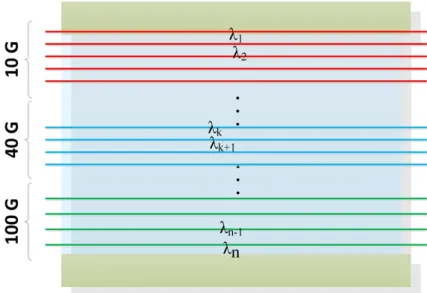
We also propose two novel approaches for the IA dynamic lightpath provisioning problem. The first approach, Fixed Wavelength-Interval Allocation (FWIA), partitions the wavelengths into groups, assigns each group to a different line rate, and establishes lightpaths with different modulation formats over the assigned wavelength groups. This approach exploits the advantage of placing different modulation formats into separate channels and they have adjacency with other modulation formats only at the boundaries of intervals. The second algorithm is the Weighted-RWA (W-RWA), which captures the instantaneous state of the network and assigns weight values according to affecting impairments using an auxiliary graph. The algorithm works for minimizing the effects of XPM and leaves more feasible wavelengths for future requests, while avoiding damaging already established lightpaths. Since the weight assignment process can be made off-line, the W-RWA makes use of idle time before any request comes. We evaluated our algorithms through simulations, and compared with existing methods.
Another important parameter for signal quality is the launch power of both the actual signal and the neighboring signals. In the last part of the thesis, we evaluated the effects of launch power, and proposed two practical approaches for appropriate launch power determination to maximize the established connections. In Worst-case Best-case Average (WBA), average optical reach for worst and best cases is used to determine the launch power. In Impairment-Aware Launch Power Determination (I-ALPD), impairments along the path are considered in a practical way to determine the launch power. I-ALPD tracks the current state of the network, and assigns weight values to the wavelengths according to the impairments. I-ALPD uses an auxiliary graph to capture the PLIs on channels with a weight assignment scheme. The proposed algorithms are compared with existing approaches. The results indicate that overall network performance can be improved by selecting the appropriate launch powers to establish the lightpaths, considering the current state of the network.
F˙IZ˙IKSEL KATMAN BOZUCU ETK˙ILER˙I GÖZET˙ILEREK
ÇOKLU VER˙I ˙ILET˙IM HIZLI DALGABOYU BÖLÜMLEMEL˙I ÇO ˘GULLAMA A ˘GLARINDA D˙INAM˙IK I ¸SIKYOLU KURULUMU
ÖZET
Artarak yayılan ˙Internet kullanımı ve yeni uygulamalar, ˙Internette ba˘glantı ihtiyaçlarını ve ihtiyaçlardaki çe¸sitlili˘gi artırmaktadır. Bu artı¸s omurga a˘glarda kullanılan ileti¸sim hızlarında iyile¸stirmeler gerektirmektedir, örne˘gin 10G yerine 40G/100G kullanılması. Ancak a˘g bile¸senlerinin tümünün aynı anda iyile¸stirilmesi mümkün olmadı˘gı gibi her zaman istenilen bir ¸sey de de˘gildir. Artan bantgeni¸sli˘gi ihtiyacını Dalgaboyu Bölümlemeli Ço˘gullama (Wavelength Division Multiplexing, WDM) ile kar¸sılayan servis sa˘glayıcılar, artan çe¸sitlili˘ge çözüm olarak, herbir dalgaboyunda farklı veri ileti¸sim hızında ileti¸sim yapılmasını mümkün kılan Çoklu Veri ˙Iletim Hızlı (Mixed Line Rate, MLR) a˘gları kullanmaya ba¸slamı¸slardır. MLR, farklı veri iletim hızlı kanalların aynı a˘g üzerinde yer alabilmesini sa˘glayan mimariye verilen isimdir.
MLR mimarisi saydam, yarı-saydam ve opak a˘glarda kurulabilir. Opak a˘glarda, ileti¸sim noktadan-noktaya hatlar üzerinden gerçekle¸stirilir. Herbir dü˘gümde sinyal yeniden üretilir. Yarı-saydam a˘glarda sinyal mümkün oldu˘gu kadar optik katmanda kalır. Saydam a˘glarda ise sinyal ara dü˘gümlerde i¸slenmez, yalnızca anahtarlanır. Saydam a˘glarda, optik sinyal fiziksel katmandaki bozucu etkilere maruz kalır. Bu bozucu etkiler sinyalin ilerledi˘gi yol boyunca birikerek sinyal kalitesinin azalmasına sebep olur. Bu kalite kaybı, hedef dü˘gümde sinyalin do˘gru olarak okunamamasına sebep olabilir. Gürültü bu bozuklukların en önemlilerindendir ve esas olarak yükselteç gürültüsü ve hat karı¸sımından kaynaklanır. Fiziksel katmandaki di˘ger bozukluklara örnek olarak; sönümleme, dispersion ve di˘ger kayıplar sayılabilir. Bunların dı¸sında sinyal, do˘grusal olmayan bozukluklardan da etkilenir. Bunlara örnek olarak da, kendi faz modülasyonu (self-phase modulation, SPM), çapraz faz modülasyonu (cross-phase modulation, XPM) karı¸sımı vb. sayılabilir. Bu bozukluklar sırasıyla kendi veya kom¸su sinyalin yo˘gunlu˘gunda olu¸san de˘gi¸simlerin sinyal fazında yarattı˘gı bozulmaları ifade eder.
Dinamik ortamlarda, ba˘glantı istekleri gelirler, belirli bir süre sistemde kalırlar ve sona erdirilirler. Her bir ba˘glantı iste˘gi için bir ı¸sıkyolu kurulur ve bu ı¸sıkyolu talep edilen ba˘glantı süresi bitiminde sonlandırılır. Gelen ba˘glantı istekleri için, a˘gın o anki durumunu dikkate alarak uygun yol ve dalgaboyunun atanmasına yönlendirme ve dalgaboyu atama (Routing and Wavelength Assignment, RWA) problemi denir. Amaç uygun yol ve dalgaboyunu seçerek, kurulabilecek ı¸sıkyolu sayısının mümkün oldu˘gu kadar artırmak, di˘ger bir ifade ile ba˘glantı isteklerinin reddedilme oranının azaltmaktır. I¸sıkyolu kurma problemi, yönlendirme ve dalgaboyu atama problemine ilave olarak, ba˘glantı yönetimi ve sinyal kalitesi ile de ilgilenir. Fiziksel katmandaki bozucu etkilerin gözetilerek ı¸sıkyolu kurulumu problemi, a˘g katmanında uygun yol
ve dalgaboyu bulunması ile fiziksel katmanda sinyal kalitesinin kabul edilebilir seviyede olmasını sa˘glaması sebebiyle birden fazla katmanı ilgilendiren bir iyile¸stirme problemidir.
Omurga a˘glarda, 10G veri iletim hızı için aç-kapa modülasyonu (on-off keying, OOK) yaygın olarak kullanılmaktadır. Bu modülasyon tekni˘gi ile yüksek kapasiteli veri iletimi yapılmak istendi˘ginde sinyal üzerindeki gürültünün etkisi daha da artmaktadır. Bu sebeple yüksek kapasiteli veri ileti¸simi için geli¸smi¸s modülasyon teknikleri uygulanır, örne˘gin; "differential quadrature phase shift keying (DQPSK)" ve "dual-polarization quadrature phase shift keying (DP-QPSK)". Bu modülasyon teknikleri fiziksel katmandaki bozucu etkilere kar¸sı oldukça hassastırlar. Ayrıca OOK kanalların, bu modülasyonlar üzerinde yarattı˘gı XPM etkisi önemli bir bozucu etkidir. Bu sebeple, zaten tek iletim hızlı a˘glarda önemli olan fiziksel katmandaki bozucu etkilerin gözetilerek ı¸sıkyolu kurulması problemi, çoklu veri iletim hızlı a˘glarda daha da önem kazanmaktadır. Problemin iki ilave boyuta daha çözüm getirmesi gerekmektedir; aç-kapa modülasyonlu sinyallerin geli¸smi¸s modülasyonlu sinyaller üzerindeki XPM etkisi ve kapasite-erim dengesi.
Çoklu veri iletim hızlı a˘glarda, statik trafik durumu için tasarım problemi konusunda pek çok çalı¸sma olmasına ra˘gmen, dinamik durumlara yönelik yapılmı¸s çalı¸sma sayısı çok fazla de˘gildir. Bu tez çalı¸smasında, fiziksel katman bozukluklarını dikkate alarak, çoklu veri ileti¸sim hızlı a˘glarda dinamik olarak gelen ba˘glantı istekleri için ı¸sıkyolu kurma problemi ele alınmı¸stır. Problemde verilenler; dinamik olarak gelen farklı kapasitelerde ba˘glantı istekleri, fiziksel topoloji, fiziksel hatların ta¸sıyabildi˘gi dalgaboyu miktarı, a˘gın anlık durumu ve fiziksel katman bozukluklarını dikkate alırken kullanılacak olan parametrelerdir. Problemde istenilen ise; gelen ba˘glantı isteklerinin mümkün oldu˘gu kadar fazlasını kurabilmek maksadı ile uygun yol ve dalgaboyunun bulunmasıdır. Bunu gerçekle¸stirirken, hem kurulacak olan ı¸sıkyolunun sinyal kalitesinin kabul edilebilir bit hata oranını kar¸sılaması, hem de sistemde daha önceden kurulmu¸s olan ı¸sıkyollarının sinyal kalitesinin kabul edilebilir sınırların altına inmesini engellemek gerekmektedir. Bu tez çalı¸smasında, kurulabilen ı¸sıkyolu miktarını artırmak maksadı ile ı¸sıkyolunun sisteme giri¸s gücü de ayrıca ele alınmı¸stır. Problemin çözümüne yönelik çe¸sitli sezgisel algoritmalar önerilmi¸stir. Öncelikle tersine-ço˘gullama (inverse multiplexing, IM) temelli yakla¸sımlar de˘gerlendirilmi¸stir. Bu yakla¸sımda, yüksek veri iletim kapasiteli ba˘glantı iste˘ginin, fiziksel katman bozuklukları sebebi ile kurulamaması durumunda, bu istek, daha dü¸sük kapasiteli, birden çok veri ileti¸sim kanalı yardımı ile kurulur. A˘g katmanındaki uygulamalar, tersine-ço˘gullama tekni˘gi kullanarak, gelen ba˘glantı iste˘ginin kaynak dü˘gümde daha dü¸sük ba˘glantı isteklerine bölünmesini, bu isteklerin herbirinin ayrı ileti¸sim kanalı üzerinden iletilmesini ve hedef dü˘gümde birle¸stirilmesini mümkün kılmaktadır. Önerilen tersine-ço˘gullama yakla¸sımlı yöntemler üç farklı yol bulma yöntemi kullanır: En kısa yol (Shortest Path, SP), en az sekme (Minimum Hop, MH) ve yo˘gunlu˘gun en az oldu˘gu yol (Least Congested Path, LCP-BB). Herbir yol bulma yöntemi ile iki farklı dalgaboyu atama yakla¸sımı uygulanmı¸stır: En iyi bit hata oranı (Best BER, BB) ve en uzak aralıklı dalgaboyu (Maximum Spectral Distance, MSD).
Fiziksel katman bozukluklarını dikkate alarak dinamik ı¸sıkyolu kurulumu problemi için önerilen di˘ger sezgisel yöntemler ise; farklı veri ileti¸sim hızlarına sabit dalgaboyu aralı˘gı atama (Fixed Wavelength-Interval Allocation, FWIA) ve a˘gırlıklı yönlendirme ve dalgaboyu atama (Weighted-RWA, W-RWA) yakla¸sımlarıdır. Bu yakla¸sımların
ilkinde, herbir veri ileti¸sim hızı için belli bir dalgaboyu aralı˘gı önceden belirlenir, tahsis edilir. Burada amaç farklı modülasyonların birbirleri üzerindeki, özellikle de OOK kanalların di˘ger modülasyonlar üzerinde etkilerini en aza indirmektir. A˘gırlıklı yönlendirme ve dalgaboyu atama yakla¸sımda, a˘gın anlık durumu takip edilir ve bir yardımcı graf kullanılarak fiziksel katmandaki bozukluklara kar¸sılık a˘gırlık ataması yapılır. Bu yöntem, XPM etkisinin azaltılmasını, var olan ı¸sıkyollarının en azının etkilendi˘gi yolun bulunmasını ve daha sonra gelecek olan ba˘glantı istekleri için daha fazla uygun yol bırakılmasını hedeflemektedir. A˘gırlık ataması, ı¸sıkyollarının kurulması veya serbest bırakılması durumunda yapılaca˘gından, sistemin bo¸sta oldu˘gu zamanı kullanarak yapılması mümkündür. Önerilen algoritmalar var olan algoritmalar ile kar¸sıla¸stırılmı¸stır.
Sinyalin kalitesini etkileyen önemli bir faktör de hem sinyalin kendisinin, hem de kom¸su sinyallerin sisteme giri¸s gücüdür. Tez çalı¸smasının son bölümünde sinyalin sisteme giri¸s gücünün etkisi de˘gerlendirilmi¸stir. Sinyal giri¸s gücünün do˘gru seçilmesi ile bozucu etkileri azaltmak ve kurulabilecek ı¸sıkyolu sayısının artırmak mümkündür. Sinyal giri¸s gücünün do˘gru seçilmesi maksadı ile iki yeni yöntem önerilmi¸stir. Önerilen yöntemler; iyi-durum kötü-durum ortalaması (Worst-case Best-case Average, WBA) ve fiziksel katman bozukluklarını dikkate alan giri¸s gücü belirleme (Impairment Aware Launch Power Determination, I-ALPD) yöntemleridir. Bu yöntemlerden ilkinde, kötü durum ve iyi durum senaryoları için ı¸sıkyolunun kurulabilece˘gi en uzun mesafeler bulunur. Bulunan mesafelerin ortalaması ve kurulacak ı¸sıkyolunun uzunlu˘gu bilgisi kullanılarak atanacak giri¸s gücü tespit edilir. Önerilen bir di˘ger yöntem olan, fiziksel katman bozukluklarını dikkate alan giri¸s gücü belirleme yönteminde, yol boyunca etkili olan bozukluklar pratik bir ¸sekilde hesaba katılırlar. Bu yöntemde a˘gın anlık durumu takip edilir ve bir yardımcı graf kullanılarak fiziksel katmandaki bozukluklara kar¸sılık a˘gırlık ataması yapılır. Önerilen algoritmalar var olan yöntemler ile kar¸sıla¸stırılmı¸stır. Sonuçlar, a˘gın anlık durumu dikkate alınarak uygun sinyal giri¸s gücü seçilmesinin, gelen istekleri reddetme oranı açısından performans artı¸sı sa˘gladı˘gını göstermi¸stir.
1. INTRODUCTION
Network operators are facing a continuous increase in terms of diversity of both traffic demands and bandwidth due to new services and bandwidth-consuming applications on the Internet. Since it is impractical and perhaps even undesirable to upgrade all legacy (10G) transmission components to higher line rates (e.g., 40G, 100G) at once, WDM optical networks support mixed line rates (MLR) to meet the requirements for both diversity and capacity increase, together. MLR refers to an architecture where different line rates on different wavelengths can coexist on the same fiber.
MLR architectures can be built over transparent, as well as translucent or opaque optical networks. In opaque networks, data transmission occurs over point-to-point links so that the signal is regenerated at every intermediate node along transmission channel. The regeneration of optical signal is done using optical-electronic-optical (OEO) conversion. In translucent architecture, regenerators are placed sparsely. It eliminates much of the electronic process and allows a signal to remain in the optical domain as much as it can [1].
In transparent networks, OEO conversions are not used at the intermediate nodes. The transmission occurs in optical domain. The optical channels cannot be processed at intermediate nodes on optical level but can be switched. Along the transparent optical path, a signal undergoes a number of physical-layer impairments (PLI) and its quality degrades as it travels through several optical components [1]. A major impairment is the accumulated noise, mainly due to amplified spontaneous emission (ASE) and crosstalk (XT). Optical transmission channels are also affected by non-linear impairments such as self-phase modulation (SPM) and cross-phase modulation (XPM), which are the shifts in the phase of a signal caused by the change in intensity of the signals itself or on the neighboring wavelengths, respectively. In optical WDM networks, end users communicate with one another via all-optical WDM channels, which are referred to as lightpaths [2]. In dynamic traffic case, a lightpath is set up for each connection request as it arrives, and it is released
after some finite amount of time. Finding an appropriate route and assigning a wavelength to given connection requests is called the Routing and Wavelength Assignment (RWA) problem. The objective of the problem is to set up lightpaths in a manner that minimizes the amount of connection blocking, or that maximizes the number of connections that are established in the network at any time. Lightpath provisioning, in addition to RWA, deals with connection management and quality of signal. Impairment-aware (IA) lightpath provisioning problem is a cross-layer optimization problem, which finds the appropriate path and wavelength at the network layer and assures the acceptable signal quality at the physical layer.
For 10G line rate signals, on-off keying (OOK) with direct detection is the most commonly used transmission technique [3]. Higher bandwidth results in a linear increase in noise level of the intensity-modulated channel. Thus, higher line rates (e.g., 40G, 100G) require advanced modulation techniques such as: differential quadrature phase shift keying (DQPSK) and dual-polarization quadrature phase shift keying (DP-QPSK). DQPSK and DP-QPSK modulated signals are highly susceptible to PLIs. Moreover, coexistence of OOK signals with advanced modulation formats induces high XPM on xPSK signals [4, 5]. Accounting for PLIs during the provisioning phase, which is an important problem in single-line-rate WDM networks acquires even larger importance in MLR networks. In MLR networks, the problem has two additional dimensions: the disruptive interaction of different modulation formats, and the trade-off between capacity and optical reach1.
In this thesis, the impairment-aware lightpath provisioning problem is studied for dynamic connection requests in MLR networks. We first investigate the effects of inverse multiplexing (IM), which is a technique that tries to exploit the advantage of transmitting the signals with low line rates, where the high line rate is not possible due to impairments. The network layer applications enable to inversely multiplex the connection requests with high line rates into smaller line rates at the source node, propagate them separately over a transparent MLR network, and then combine them back at the destination node. We propose various IM-based schemes to account for impairment-aware dynamic lightpath provisioning in MLR optical networks.
1Reach is the distance an optical signal can travel before the signal quality degrades to a level that
The proposed schemes use three different path-selection algorithms: shortest path (SP), minimum hop (MH) path, and least congested path (LCP). Two different wavelength-assignment schemes are employed with each path-selection algorithms: Best Bit Error Rate (BB) and maximum spectral distance (MSD).
We also propose two novel approaches for IA lightpath provisioning problem. The first approach, Fixed Wavelength-Interval Allocation (FWIA), partitions the wavelengths into groups, assigns each group to a different line rate, and establishes lightpaths with different modulation formats over the assigned wavelength groups. The second algorithm is the Weighted-RWA (W-RWA) scheme, which captures the instantaneous state of the network and assigns weight values according to affecting impairments. The algorithm works for selecting the wavelengths which are less exposed to impairments while trying to leave feasible wavelengths for future requests, and avoiding damaging the existing lightpaths. Since the weight assignment process can be made off-line, the W-RWA makes use of idle time before any request comes.
Another important parameter for signal quality is the launch power of both the actual signal and the neighboring signals. We also evaluate the effects of launch power and propose two practical approaches for appropriate launch power determination. In the Worst-case Best-case Average (WBA), average optical reach for worst and best cases, in terms of impairments, is used to determine the launch power. In Impairment-Aware Launch Power Determination (I-ALPD), impairments along the path are considered in a practical way to determine the launch power. I-ALPD tracks the current state of the network, and assigns weight values to the wavelengths according to the impairments. I-ALPD uses an auxiliary graph to capture the PLIs on channels with a weight assignment scheme.
The outline of this thesis is as follows: A brief explanation on the enabling technologies of MLR optical WDM networks and optical transmission are given in Chapter 2. PLIs and BER estimation model used to evaluate the signal quality are also given in this chapter. In Chapter 3, the formal definition of the problem, and previous studies related to the subject of this thesis are given. In Chapter 4, the effects of IM in MLR networks are evaluated and proposed six IM-based approches are explained. Proposed approaches are compared with one another and the algorithms without IM. In Chapter 5, two novel approaches proposed for IA lightpath provisioning are discussed.
The performances of the proposed approaches are compared with other PLI-aware MLR lightpath provisioning algorithms. In Chapter 6, we present the effects of launch power on signal quality. Two approaches to determine appropriate launch power in MLR networks are discussed. The performances of proposed launch power determination approaches are compared with existing approaches. Chapter 7 concludes the thesis.
2. OPTICAL WDM TRANSMISSION
2.1 Introduction
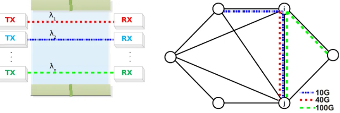
In optical Wavelength Division Multiplexing (WDM) networks, the optical transmission spectrum is carved up into a number of non-overlapping wavelength channels on which each channel can carry a single communication (Figure 2.1(a)). End users communicate with one another via WDM channels, which are referred
(a) Lightpaths at different wavelengths. (b) Different line rates sharing the same link. Figure 2.1: MLR on WDM optical networks.
to as lightpaths [2]. Modulated signals are put on the channels from one end by a laser transmitter (TX) to be received by the receivers (RX); those are tuned to the same wavelength at the other end of the communication channel (Figure 2.1(a)). Each channel may transport different types of traffic, such as SONET/SDH over one wavelength, ATM over another, and TDM voice, video or IP over another, using the same infrastructure. In opaque networks, data transmission occurs over point-to-point links so that the signal is regenerated at every intermediate node along transmission channel. The regeneration of optical signal is done using optical-electronic-optical (OEO) conversion. In translucent architecture, regenerators are placed sparsely. It eliminates much of the electronic process and allows a signal to remain in the optical domain as much as it can. In transparent networks, the transmission occurs in optical domain. The optical channels are not processed at intermediate nodes. The
number of wavelengths, which each fiber can carry simultaneously, is limited by the physical characteristics of the fiber and the optical technology used. WDM makes it possible to transfer data at different bit rates, over different channels on the same link (Figure 2.1(b)), which is called Mixed (or Multi) Line Rate (MLR) [7, 8]. The terms Optical NetworkandOptical WDM Networkare used interchangeably throughout this thesis.
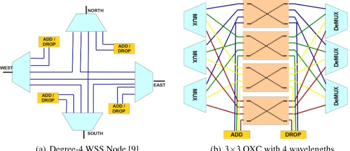
AnOptical Network consists of optical nodes interconnected with fiber links. Optical networks are conceptually segmented in three as: Access, metro, and core/backbone networks. The access segment of the network refers to the portion between customer location and its central office. Interconnected central offices constitute metro areas for carriers. The backbone segment interconnects metro segments. In optical backbone networks, single mode (SM) fibers and intermittently placed in-line amplifiers are used for connecting nodes, called reconfigurable optical add-drop multiplexers (ROADM). Figure 2.2 shows the architecture of two different broadly used ROADM types.
(a) Degree-4 WSS Node [9]. (b) 3×3 OXC with 4 wavelengths. Figure 2.2: Different node types.
A Wavelength Selective Switch (WSS) ROADM (Figure 2.2(a)) consists of WSS, channel monitor, and amplifier. WSS is a device that extracts and inserts the light. WSSs use Fiber Bragg Gratings (FBG) to separate the wavelengths. FBGs are prism like devices that separate the light into component colors. WSS uses different switching technologies to select the frequency. Currently, the two major switching technologies are micro electro mechanical systems (MEMS) and liquid crystals (LCoS). Channel monitors continuously monitor the optical power level of wavelengths.
AnOptical Cross Connect (OXC)switches optical signals from input ports to output ports. It consists of demultiplexers (DeMUX), optical switches, and multiplexers (MUX) (Figure 2.2(b)). In order to route each wavelength separately, each input fiber is connected to demultiplexers which spatially separate the wavelengths on the fiber. A typicaln×nOXC connectsninput fibers, each carryingW different wavelengths to noutput fibers usingW optical switches, each for one wavelength. Each wavelength is switched accordingly, and all the wavelengths going through the same output port are multiplexed on to the output fiber. The optical switch can have strictly nonblocking active-splitter active-combiner architecture [10].
In ROADM systems, the flexibility of the mesh network is extended by Colorless, Directionless, and Contentionless features of optical nodes. Colorless feature at an add/drop port is the ability of tunable transponders to have transparent wavelength access to all WDM network ports. Directionless feature is ability of tunable transponders to have non-blocking access to all ports. Contentionless is ability to avoid contention.
The optical signal loses its power along the path it travels. Optical Amplifiersmake long distance optical transmission possible by providing a power boost to the signals. Optical signal is not converted into the electrical domain but its power is increased. Erbium-Doped Fiber Amplifiers (EDFA) are commonly used, where the channels on the fiber are required to be amplified. The part of a link between amplifiers is called a span, and its length is nearly 80 km. The main disadvantage of an EDFA is the noise it adds to the signal. The noise at an EDFA is spontaneous emission, thus it is called amplified spontaneous emission (refer to Section 2.2.1).
2.1.1 Transmission of a signal
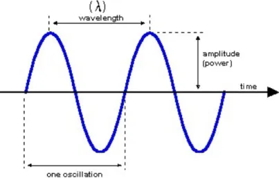
Wave Theorydescribes light as an electromagnetic wave. Electromagnetic waves have four basic properties: intensity, wavelength (or frequency), polarization, and phase. For ideal conditions, these properties for an optical carrier are constant, except for modulation.
Intensitycan be referred to as power of the optical carrier. It is a measure of the energy flux (rate of transfer of energy through a surface), averaged over a certain time period. To find the intensity, energy density (that is, the energy per unit volume) multiplid by
the velocity at which the energy is moving. The resulting vector has the units of power divided by area (i.e.,W/m2). Greater intensity means more photons but the energy of each is exactly the same.
Polarization describes the orientation of oscillations for waves. The polarization of light is described by specifying the orientation of the wave’s electric field at a point in space over one period of the oscillation. The phase of a wave is the fraction of a complete cycle corresponding to an offset in the displacement from a specified reference point at time t = 0.
Thewavelength(λ) is the spatial period of a sinusoidal wave, the distance over which the wave0s shape repeats. The frequency is the number of oscillations per second. Wavelength is inversely proportional to the frequency of a sinusoidal wave moving
Figure 2.3: Wavelength and frequency relation.
at a fixed wave speed; waves with higher frequencies have shorter wavelengths, and lower frequencies have longer wavelengths. The wavelength λ of a sinusoidal light traveling at constant speed is given by:
λ = c
f (2.1)
where c is the velocity of light (3×10⁸m/s), f is the frequency (hertz), and λ is the wavelength (meters). The speed of light in fiber is nearly 2×10⁸m/s, and the wavelengths are correspondingly different. Frequency or wavelength terms can be used to characterize an optical WDM signal. Wavelength is measured in units of nanometers (nm) or micrometers (µm or microns). In WDM networks, a fiber carries a number of optical signals simultaneously in or around C-band (1530-1565 nm). These optical
signals must obviously be at different carrier wavelengths. Thus, it is convenient to refer to the available bandwidth as a set of channels. Each optical signal is allotted a distinct channel, and each channel has sufficient bandwidth to accommodate the modulated signal. In order to avoid interference between different optical signals, each channel is separated from the other channels by a certain minimum bandwidth calledchannel spacing. Channel spacing is also measured in units of wavelengths or frequencies. The relationship between the frequency spacing∆f and the wavelength
spacing∆λ is given as [11]:
∆f = c
λ02∆λ (2.2)
Wavelength spacing of 0.8 nm corresponds to a frequency spacing of 100 GHz, at wavelengthλ0= 1550 nm.
2.1.2 Modulation
Modulation is the process of encoding an electrical signal onto the carrier. The optical carrier wave is formulated as [12]:
E(t) =eAcos(ωˆ 0t+ϕ) (2.3)
where E is the electric field vector, ˆe is the polarization unit vector, A is the amplitude, ω0 is the carrier frequency, and ϕ is the phase. Thus, it is possible to choose one of the variables to modulate a signal: amplitude, frequency, or phase. The modulation techniques are called amplitude-shift keying (ASK) (Figure 2.4 (a)), frequency-shift keying (FSK) (Figure 2.4 (b)), and phase-shift keying (PSK) (Figure 2.4 (c)), depending on whether the amplitude, frequency, or phase is modulated.
(a) ASK (b) FSK (c) PSK
Figure 2.4: Different keying techniques.
Amplitude Shift Keying is the simplest and the most common technique, which consists of changing the signal power (intensity) between two levels, 1 and 0 levels. The laser used for transmission is eitheronoroff depending on the value of the signal;
therefore it is also called On-Off Keying (OOK) [12]. The information can be coded in two symbols 0 and 1, using only the amplitude. OOK is commonly used for lower (≤10G) transmission rates.
Capacity and flexibility of optical networks can be increased using higher line rates (≥40G). Using amplitude modulation for high line rates increases the requirement for bandwidth. Higher bandwidth results in linear increase at the noise power level of the communication channel. Increased noise results in shorter optical reach, and more regenerators for longer distances. Increasing the laser power will not work because of increasing non-linear effects. Thus, channel bit rate can be increased using advanced modulation formats.
Phase Shift Keying is the modulation using the phase of the signal. This can be achieved simply by defining a relative phase shift from the carrier. Phase modulation is used for higher line rates.
Quadrature Phase Shift Keyingis a form of PSK in which two bits are modulated at once, selecting one of four possible carrier phase shifts (0,π/2,π, 3π/4).
Differential Quadrature Phase Shift Keying (DQPSK) encodes information in the differential optical phases (∆φ) between successive bits, where ∆φ may take one of four values [0, π/2, π, 3π/4]. Since each symbol transmits two bits of information, the symbol rate is half of the total bit rate. Spectral efficiency of this modulation technique makes it suitable to carry 40 Gbps channels [13].
Dual Polarization-Quadrature Phase Shift Keying (DP-QPSK) decomposes a signal into two polarizations of the same frequency at 90◦ from each other in order to avoid mutual interaction as they are being launched into the fiber. One signal is transmitted in the horizontal polarization and the other in the vertical polarization. These two signals can be combined or split up using an optical polarization beam splitter. By combining the effects of dual polarization and DQPSK, we can have four bits per symbol: one from each polarization and two from QPSK. This makes DP-QPSK suitable for 100 Gbps [5], and within the bandwidth requirements of existing WDM grid.
2.2 Physical Layer Impairments (PLI)
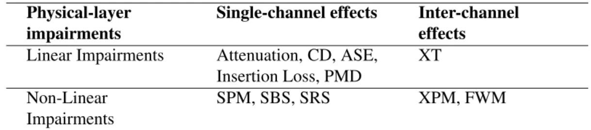
The PLIs can be classified into two categories: linear and non-linear [1]. Linear effects are static in nature, and they are independent of signal power. They affect each wavelength individually. Their effects on end-to-end lightpaths can be estimated using link parameters; hence, linear impairments can be handled as a constraint on routing or other optical WDM network problems. Non-linear effects, on the other hand, are dynamic in nature and are more complex because they not only affect each optical channel individually but also cause disturbance and interference between them. The PLIs can also be classified according to the scope of the effects, such as single-channel effects and inter-channel (or multi-channel) effects. The single-channel effects can be estimated using the channel (bit rate, wavelength, modulation format, etc.) and the path characteristics (fiber loss, chromatic dispersion, amplifiers power, etc.). On the contrary, the inter-channels effects depend not only on the channel and path parameters, but also on other lightpaths deployed in the network at the specific time. The single and inter-channel impairments are summarized in Table 2.1.
Table 2.1: Single and inter-channel impairments. Physical-layer
impairments
Single-channel effects Inter-channel effects
Linear Impairments Attenuation, CD, ASE, Insertion Loss, PMD XT Non-Linear Impairments SPM, SBS, SRS XPM, FWM 2.2.1 Linear impairments
Attenuationis the decrease in power of an optical signal as the signal travels along the path (Figure 2.5). When determining the maximum distance that a signal can be sent for a given transmitter power and receiver sensitivity, attenuation must be considered. Receiver sensitivity is the power required by a receiver to detect a signal. LetP(L)be the power of the optical pulse at distanceL(km)from the transmitter, and letα be the attenuation (loss) constant of the fiber (dB/km). Attenuation is characterized in [1] by: P(L) =10αL/10Pin (2.4)
where Pin is the signal power at transmitter. To keep the power of signal within the
Figure 2.5: Attenuation of optical signal.
Amplified spontaneous emission (ASE)is the noise produced by optical amplifiers. This noise accumulates as the amplifiers cascade along the lightpath. ASE noise occurs in both the forward and reverse directions, as shown in Figure 2.6. Forward ASE is a direct concern to system performance because that noise will co-propagate with the signal to the receiver. Backward ASE can lead to degradation of incoming signal power, which can easily be compensated.
Figure 2.6: ASE noise production.
ASE noise is one of the major contributors to the total optical noise for long haul transmission systems. ASE noise power measured over a given spectral bandwidthB0 can be calculated using the following formula [11]:
PASE =2nsp.h.f.B0(G−1) (2.5) where PASE : Average amplifier ASE noise power, W
nsp : spontaneous emission factor (or population inversion parameter) h : Plank’s constant 6.626069×10⁻³⁴js
f : center frequency, assuming 193.30 THz (1552.12 nm) B0 : Optical channel bandwidth
G : Gain of amplifier
Dispersionis the time-domain spreading or widening of a pulse duration as it travels through a fiber. As a pulse gets wider, its shape changes. Dispersion limits the bit spacing and the maximum transmission rate on an optical channel. Too much dispersion in the network leads to degradation of signal quality and loss of data. On
the other hand, having zero dispersion leads to non-linear impairments (i.e., FWM) in WDM networks.
Optical pulse has different components (wavelength, polarization state). The difference in velocity caused by wavelength is calledchromatic dispersion, and the difference in velocity caused by different polarization modes is called polarization mode dispersion.
Polarization Mode Dispersion (PMD)occurs when two different polarizations of light in a waveguide, which normally travel at the same speed, travel at different speeds due to birefringence (double refraction) effect of light. Birefringence is a property of optical materials for which light, polarized along the x axis, experiences a different index of refraction, and travels at a different speed than does light polarized along the yaxis. PMD causes inter-channel-interference (ICI), as shown in Figure 2.7.
Figure 2.7: PMD effect on channels of fiber.
PMD becomes a problem for higher rates (≥40G), and long distances. On a transparent transmission, PMD effect can be evaluated using the following formula [14]:
B× v u u t M
∑
k=1 D2PMD(k)×L(k)≤δ (2.6)whereBis the bit rate, transparent segment of the lightpath consists ofMspans, andkth span has length ofL(k). DPMD(k)represents the PMD coefficient of thekthspan, which is measured in ps/√km. The parameter δ represents the fractional pulse broadening caused by PMD, which is typically less than 10% of a bit’s time slot for which the PMD can be tolerated [1]. PMD values vary from fiber to fiber in the range of 0.01-10 ps/√km[15].
Chromatic Dispersion (CD) is pulse spreading due to the fact that different wavelengths of light propagate at slightly different velocities through the fiber.
Chromatic dispersion can be defined as the frequency dependence of the refractive index nf. When an electromagnetic wave interacts with the bounds of transmission medium, the response of the medium differs depending on the optical frequency f. It yields pulse broadening, which accumulates along the path. CD induces inter-symbol interference (ISI), as shown in Figure 2.8. Chromatic dispersion is deterministic and
Figure 2.8: Effects of chromatic dispersion.
linear. It is not affected by the environment. Thus, it can be predicted and compensated. Dispersion compensating fibers (DCF) have negative dispersion (i.e., -85 ps/nm.km) to compensate the positive dispersion of standard single mode fiber (SSMF). But compensation is made for only the center channel of the band of wavelengths. Other WDM channels are left with residual dispersion. So, WDM network design requires knowledge of end-to-end CD as a function of wavelength, especially for long distances. Insertion Loss is introduced by the optical components, such as couplers, filters, multiplexers/demultiplexers, and switches. It is usually independent of wavelength. Loss amount at a switch is dependent upon the number of switching elements that a signal must pass through. A P×P switching element is composed of 1×P active splitting elements andP×1 active combining elements, in which basic building block is a 2×2 crossbar switch. The active splitter half of theP×Pswitch consists of log2P stages of 1×2 elements, and similarly combiner half of the P×P switch consists of log2P stages of 2×1 elements. In this architecture, all signals have to pass through the same number (2log2P) of individual switch elements. Each switch element has a characteristic loss, Ls in dB, associated with it. An additional attenuation occurs during the on-off transfer process of the signal. This waveguide/fiber coupling loss is represented by Lw and includes the reflection losses and mismatch losses. Thus insertion loss ofP×Pswitch is given by [10]:
Crosstalk (XT) is signal noise, which occurs due to the non-ideal isolation of demultiplexers, switching elements and multiplexers inside an OXC. It is the leakage from neighboring wavelength or same wavelength at different input port. Linear crosstalk depends on the ratio of the optical powers of two channels. There are two different types of switch crosstalk: intraband and interband crosstalk. Due to non-ideal isolation of the switching element of OXC, lightpaths crossing the same node over same wavelength of actual lightpath incur some noise, called intraband crosstalk (see Figure 2.9 (a)). It cannot be removed by optical filters and therefore accumulates through the network. Also the neighboring lightpath coming from the same input of the OXC with adjacent wavelengths induce some noise, referred to as interband crosstalk (see Figure 2.9 (b)). The crosstalk noise power of each OXC can be formulated as
Figure 2.9: Switch crosstalk types. follows [10]: X Tk,λ = N
∑
n=1 X TswPkνλ,n+X TdmxPkνλ∓1 (2.8) where N is the input port number, Pk is the signal power of affecting port at the given node. X Tsw andX Tdmxaccount for isolation factor of switch and dumultiplexer, respectively. νλ,nandνλ∓1are binary variables indicating the existence of the relatedinterband and intraband crosstalk. First part of the equation gives the total crosstalk caused by the lightpaths which have the same wavelength. The last part of the equation gives the crosstalk caused by the signals from the same input port, due to non-ideal demultiplexer isolation. Considering gains and losses along the lightpath, accumulated crosstalk power at the destination node (k+1) can be calculated recursively using the
approach given in [10]:
PX T(k+1,λ) = PX T(k,λ)Lf(k,k+1)Gin(k+1,λ)
.Ldm(k+1)Lsw(k+1)Lmx(k+1)Gout(k+1,λ)Ltap2
+X Tk,λ (2.9)
whereLx indicates the loss values of different components, andGin andGout indicate the gain values due to pre/post-amplifiers.
2.2.2 Non-linear impairments
The non-linear impairments in optical fiber occur due to either change in the refractive index of the medium with optical intensity (power) or stimulated scattering [3]. Stimulated scattering arises due to the interaction of light waves (optical signals) with photons (molecular vibrations) in the silica medium. This leads to intensity dependent gain or loss. The two main effects in this category are Stimulated Brillouin Scattering (SBS) and Stimulated Raman Scattering (SRS). SBS occurs when an optical signal in fiber interacts with the density variations (such as thermally driven density fluctuations and acoustic phonons) and changes its path. Raman scattering arises from the interaction of light with the vibrational modes of the constituent molecules in the scattering medium; equivalently this can be considered as the scattering of light from optical phonons. SRS and SBS are quite similar non-linear effects. The main difference between the two is that optical phonons participate in SRS, while acoustic phonons participate in SBS.
Another set of non-linear effects arises due to the dependence of the refractive index on the intensity of the applied electric field, which is called Kerr Effect. There are three different main categories of this effect: Self-phase modulation, cross-phase modulation, and four-wave mixing. Increasing WDM channel capacity, decreasing channel spacing, and increasing optical power increase these non-linear effects. Four-Wave Mixing (FWM) is interaction between three wavelengths that produces a 4th wavelength. In a WDM system using the angular frequencies ω1,ω2, ...ωn, the
intensity dependence of the refractive index not only induces phase shifts within a channel but also gives rise to signals at new frequencies such as 2ωi−ωj and ωi+
independent of the bit rate but is critically dependent on the channel spacing and fiber chromatic dispersion. Decreasing the channel spacing increases the four-wave mixing effect, and so does decreasing the chromatic dispersion.
Self-Phase Modulation (SPM) is the non-linear interaction of a channel with itself. The Kerr Effect of a fiber leads to a phase shift of an optical signal due to its own intensity. The refractive index of the silica,n, increases with the optical power,P:
n=n0+n2 P
Ae f f (2.10)
wheren0is the linear refraction index at low powers, andAe f f is the effective area of optical mode in the fiber (typical single-mode fibers is 50-80 µm). The coefficientn2 is typically ∼2.6 x 10⁻²⁰m2/W in standard single-mode fiber [16]. Variations in the power of an optical signal result in variations in the phase of the signal. Instantaneous variations in a signal’s phase will result in instantaneous variations of the frequency around the signal’s central frequency. In the frequency domain, this effect can be seen as a spectral broadening of a signal. For very short pulses, the additional frequency components generated by SPM combined with the effects of chromatic dispersion also lead to spreading or compression of the pulse in the time domain, affecting the maximum bit rate and the BER. Optical phase shift ∆φSPM results after propagation
over distanceLis given by [16]:
∆φSPM =γ.P.Le f f (2.11)
whereγ is the fiber non-linear coefficient, and defined as: γ = cAn2ω0
e f f. ω0is the optical carrier frequency of the pulse,cis the speed of light. The effective length,Le f f takes the fiber loss,α into account, and is defined as:
Le f f =
1−e−αL
α (2.12)
Cross-Phase Modulation (XPM) is a shift in the phase of a signal caused by the change in intensity of a signal propagating at a different wavelength. XPM can lead to asymmetric spectral broadening, and combined with SPM and dispersion may also affect the pulse shape in the time domain. In XPM, the phase of the signal in one channel is altered by the intensity fluctuations of the other channels. Its impact of XPM depends on the modulation format, power and transmission rate of the involved
signals. Several approaches based on analytical approximations have been investigated [4, 17–19]. We will go with the simplified model used in [19], in this thesis. The noise contribution of an interfering OOK signal jto channeliis given as [19]:
σi2,j= φi2,jτi,j Tj ( K+1 K c1− c2 K2 K
∑
h=1 hexp −hT τi,j − 1 K2 K0∑
h=1 hc3(h) ) (2.13) whereφi,jis the phase shift,τi,jis the group delay of channel jwith respect to channeli,Kis the filtering effect,T is symbol time, andTjis the pulse width.cvalues give the
spectral shape of the OOK channel. τi,j,K0,c1,c2, andc3are given as:
τi,j = Di∆λj αi K0 = Tj/T−1 c1 = exp −Tj τi,j + Tj τi,j −1 c2 = 2 cosh T j τi,j −1 c3(h) = 2 sinh hT−T j τi,j −hT−Tj τi,j (2.14) The phase shiftφi,jinduced on channel i by channel j due to XPM is given as:
φi,j=
2γi.Pi,j
αi
(2.15) where γ is the fiber non-linear coefficient,α is the attenuation coefficient, andPi,j is
the power of the interfering channel j.
2.3 Quality of Transmission (QoT)
Along the transparent optical path, a signal undergoes various PLIs and its quality degrades as it travels through optical components. The receiver makes decision about the transmitted bit whether it is 1 or 0, and it could make a wrong decision due to low signals quality. So it is necessary to evaluate the signal quality at the receiver side. BER is an appropriate criterion to decide the quality of the signal. It is the probability of incorrect decision of a bit by the decision circuit of the receiver. Actually, BER value is not available before the lightpath is set up. Even calculating BER value instantaneously is not easy. A 10−12 BER means that one bit is received in
error for every terabit of transmitted data bits. It will take days to get reasonable sampling data. Thus, BER is estimated using the statistical and analytic models of physical-layer impairments, those taken into consideration. MLR networks adopt different modulation schemes, and each modulation scheme requires different BER evaluation models.
OSNR is the ratio between the total signal power and the noise power on the reference bandwidth.
2.3.1 Optical signal-to-noise ratio (OSNR)
OSNR is the strength of the signal compared to the level of noise. It is used to evaluate the power of signal and the power of noise over specific bandwidth.
OSNR= Preceived
Nlinear+Nnon−linear (2.16) where Preceived denotes the signal power at the receiver, and Nlinear and Nnon−linear denotes the undesired linear and non-linear noise power accumulated along the path. For a given lightpath from source to destination, output power of signal (Pout) is ruined with three main noise components: the inline amplifiers noise, node noise, fiber noise. Node noise includes switch crosstalk, and ASE noise of EDFA amplifiers. A node also has other loss sources that affect the OSNR, such as demultiplexer (Ldmx), multiplexer (Lmx), tap (Ltap), and switching element (Lsw). Besides, the signal is amplified to a certain power level before (Gin, pre-amplification), and after it is switched (Gout,
post-amplification). Optical amplifier noise (NASE) and FWM are the noise factors on the fiber. Noise factors within the node areNASE,X TDMX,X TMX,X TSW, losses induced
by components (Ldmx,Lmx,Ltap,Lsw), and the amplifier gains (Gin,Gout).
In order to evaluate linear and non-linear noise factors, we employed the staged OSNR model as in Equation 2.17 [11]:
1/OSNR =
∑
1/OSNRstages (2.17)Since the OSNR on a lightpath varies, an iterative method based on the current network state is needed to calculate the signal and noise powers propagating through the lightpath. The output noise power (Nout) of(k+1)thstage can be considered iteratively
as: Nout(k+1) = Nout(k) G(k,λ).e−αdk LdmxLswLmx +G(k,λ)e −αdk LdmxLsw hv(λ)B0 2 × Fampk+ Fampk e−αdkG(k,λ) +G(k,λ) LswLmx m
∑
j=1 PFW Mk(λ) +ε s∑
j=1 Pswk+1,j(λ) (2.18)The output signal power of(k+1)th stage is:
Pout(k+1) =Pout(k) G(k,λ).e−αdk LdmxLswLmx (2.19) 2.3.2 Bit-error rate (BER) estimation
BER differs according to modulation formats.
OOK modulation is affected mostly by ASE, CD, PMD, and SPM. BER can be approximated for OOK modulated signals as [19]:
BER≈ 1 2er f c Q √ 2 ≈ exp(−Q 2/2) Q√2π (2.20) whereQ-factor is related to signal to noise ratio as:
Q=√ 2ρ M+√M+4ρ
(2.21) where M=2B0T, B0 is the optical filter bandwidth, and T is the symbol time. The relation with OSNR is as:
ρ =nBre fT.OSNR (2.22)
where Bre f is the reference bandwidth, n is the ratio between number of noise and signal polarizations.
DQPSK modulation is commonly used for 40 Gbps transmission [18]. Most detrimental impairments for this type of modulation are ASE, CD, PMD, SPM, and XPM [19]. Especially, when a signal is transmitted adjacent to an OOK channel, XPM becomes the most detrimental effect on this signal. BER estimation for this modulation can be approximated as [19]: BER=3 8− ρ 4e −ρ ∞
∑
h Im−1 ρ 2 +Im+1 ρ 2 i2 ×sin(mπ/4) m e −m2σNL2 /2 (2.23)whereIk(x)is the k-order modified Bessel function of the first kind. ρ is the signal to noise ratio and related to OSNR through Equation (2.22). Variance of non-linear phase noise is given as:
σNL2 =σSPM2 +σX PM2 (2.24) SPM contribution of phase noise is approximated as:
σSPM2 ≈4φSPM2 /(3ρ) (2.25) φSPM is discussed in section 2.2.2. σX PM2 is given detailed in Equation (2.13).
DP-QPSK is the candidate modulation for 100G line rates [4]. DP-QPSK is also affected by ASE, CD, PMD, SPM, and XPM [19]. OOK neighboring channels have detrimental XPM effect on DP-QPSK channels. BER estimation for this modulation can be approximated as [19]: BER= 3 8− 1 2 r ρ πe −ρ/2 ∞
∑
m=1 h Im−1 2 ρ 2 +Im+1 2 ρ 2 i ×sin(mπ/4) m e −m2σNL2 /2 (2.26)SPM contribution of phase noise for this modulation is approximated as:
σSPM2 ≈2φSPM2 /(3ρ) (2.27) Gaussian Approximation: In QPSK systems, errors occur when the received signal phase is different from transmitted one by more than π/4. With the assumption of phase noise being Gaussian, phase rotation induced by noise exceeds a given value (θ) approximately byQ(√2ρsinθ). Using this information, it is possible to use BER evaluation model given in Equation (2.20), instead of Equations (2.23) and (2.26) with the following formula for Q-factor [19]:
Q= q π/4 S 2ρ( θ sinθ) 2+σ2 NL (2.28)
where S stands for effected term number (1 and 2 respectively, for QPSK and DP-QPSK).θ is used as ( [19]):
θ = (π/4)/(S+2ρ σNL2 ) (2.29) Guard Band (GB) is the number of wavelengths between two lightpaths, beyond which the effect of a lightpath on the other can be neglected. GB is obtained from the minimum spectral separation value that guarantees to have negligible detrimental
effects (e.g., noise less than 0.1 dB) induced by neighboring lightpaths. The spectral separation of channelifrom affecting channel jcan be found using following formula [20]: ∆λGB> v u u t160ρTjT gD(K)
∑
i γi2Pi2,j D2i (2.30)where ρ is the signal to noise ratio and related to OSNR through Equation (2.22), K is the filtering effect due to differential detection in phase shift keying modulation formats. gD(K)is differential or coherent detection with phase estimation and for large group delays it is defined as [20]: gD(K) =2K+3+(6 1/K).
Optical Power and Loss: In optical communication, decibel units (dB) are used to measure the power and signal levels. Logarithmic decibel units are used to represent relative values, instead of absolute values. The standard reference value for optical communication is 1 milliwatt (mW) [11]. Suppose the transmitted signal has power of Pwatts (W). In terms of dBm units, it is denoted as [3]:
PdBm=10log PmW 1mW (2.31) For example, a power of 1 mW corresponds to 0 dBm and 1µW corresponds to -30 dBm. A power of 5 mW corresponds nearly to 7 dBm.
As the signal propagates through the fiber, its power decreases due to loss occurred at optical components and attenuation on fiber. The loss ratio,Tr is defined as:
LossRatio=Tr= Pout
Pin (2.32)
where Pout and Pin are fiber or component output and input powers at a specific
wavelength, respectively. Loss ratio is always less than or equal to 1. IfPout/Pin ratio is greater than 1, than it is referred to asgain.
Theoptical loss represented with logarithmic scale value is standardized in dB units. SinceTr is always less than 1, then theoptical lossis represented as a positive number or 0: (α)dB=−10log Tr=−10log Pout Pin (2.33) As an example, if Pin is 1 mW and measured receiver power (Pout) is 0.05 mW, the optical loss value would be:
α = −10log 0.025 1 α = 13.01dB.
In this context, a signal being attenuated by a factor of 1000 would equivalently undergo a 30 dB loss.
The optical loss for fiber link is usually measured per km (dB/km). So, for example, a signal traveling through 120 km of fiber with a loss of 0.25 dB/km would be attenuated by 30 dB.
The minimum power requirement of the receiver is called thereceiver sensitivity, (R). We must ensure that the transmit power is high enough so that it can maintain signal power > R at the receiver end. That does not mean that we can increase the transmit power as much as we want to send bits across long distances. High input power causes more non-linear impairments. In addition, an upper acceptable signal power limit exists for every receiver. Therefore, the maximum input power that we can launch into the fiber, thus the reach is limited.