1 Page 1-6 © MAT Journals 2018. All Rights Reserved
Design and Analysis of level 1 and level 2 Discrete Wavelet
Transform using Vedic Multiplier
Shubhangi Singh, Shivani Marepalli, Prof. Prasheel Thakre
Department of Electronics and Communication RCOEM, Nagpur, India
Abstract
Wavelet transform is a transform which provides both the time and frequency information simultaneously. CWT (continuous wavelet transform) provides highly redundant data which needs large computation time and resource, so DWT (Discrete wavelet transform )came into picture which provides sufficient amount of information for analysis and synthesis of the original signal with a reduced computation time. In DWT, filters of different cut-off frequencies are used to analyse the input signal sequence. The signal is passed through different high pass and half band low pass filters. Filtering a signal is done by convolution of the signal sequence with impulse response of filters. Haar wavelet coefficients are used here as impulse response of filters. Then the output of low pass filters are further passed through the high pass filter and half band low pass filters to get the 2nd level DWT coefficients. We have designed level 2 DWT using Vedic multiplier (for convolution) in Xilinx 14.7 software using VHDL and their stimulated results are obtained
Keywords: Continuous wavelet transform, Discrete wavelet transform, sub band coding ,high pass filter, half band low pass filter, Vedic multiplier, convolution, haar wavelet coefficients, UrdhvaTiryagbhyam.
INTRODUCTION
Various mathematical transformations are applied to signals to obtain important information. In many cases the most distinguished information are hidden in the frequency components of the signal. Fourier transformation is applied to a signal to obtain its frequency components. The frequency spectrum of a real valued signal is always symmetric.
Fourier transformation is a reversible transform, that is it allows going back and forward, between the processed and raw signals. But it can show either time or frequency component in a particular time. Stationary signals are the signals whose frequency component does not change with time. Whereas non-stationary signals are signals whose frequency components
change with time. Fourier transform of stationary and non-stationary signals may be same. Thus, the Fourier transform is only suitable for stationary signals.
The solution to this is Short Time Fourier transform(STFT) which provides both time and frequency representation of a signal simultaneously. In STFT the signal is divided into small enough segments, where these segments are assumed to be stationary. Now a window function with a fixed width is choosen such that the stationarity of the signal is valid. The drawback of STFT is that the width of the window function is fixed which gives either good time or frequency resolution. This drawback is solved by Continuous wavelet transform.
2 Page 1-6 © MAT Journals 2018. All Rights Reserved MULTI RESOLUTION ANALYSIS
(MRA)
Analysing a signal at different frequencies with different resolutions is called MRA. Each spectral component is not resolved equally as was the case with STFT. MRA is designed to give good time resolution and poor frequency resolution at high frequencies and poor time resolution and good frequency resolution at low frequencies.
CONTINUOUS WAVELET TRANSFORM (CWT)
CWT was introduced to overcome the resolution problems of STFT . In CWT width of the window is changed for every single spectral component.
CWT(z,s)=
s ∫ ( ) ( )
z = translation parameter (which is related to the location of the window).
s = scale parameter (which is related to stretching out or compressing a signal). The wavelet is placed at beginning of signal at t=0, wavelet function at s=1 is multiplied with the signal and integrated over all time
MOTHER WAVELET
Wavelet means a small wave, where small refers to the condition that the window function is of finite length and wave refers to the condition that the signal is oscillatory.
Mother refers as the main function from where the other window functions are defined. Mother wavelet is prototype for getting other window functions.
DISCRETE WAVELET TRANSFORM (DWT)
Although the discretized continuous wavelet transform enables the computation of the continuous wavelet transform by computers, it is not a true discrete transform. As a matter of fact, the wavelet series is simply a sampled version of the
CWT, and the information it provides is highly redundant as far as the reconstruction of the signal is concerned. This redundancy requires a significant amount of computation time and resources. The discrete wavelet transform (DWT) provides sufficient information both for analysis and synthesis of the original signal, with a significant reduction in the computation time.
SUBBAND CODING
The procedure starts with passing the sequence (signal) through a half band digital low pass filter with an impulse response h[n].
Filtering a signal means convolving the input signal with the impulse response of the filter.
x[n]h[n] = ∑ [ ] [ ]
A half band low pass filter removes all the frequency above its cut off frequency ( i.e. the half of the highest frequency in the signal).
For example : if a signal has a maximum of a 4000Hz component than half band low pass filter will remove all the frequencies above 2000Hz.
After passing the signal through half band low pass filter, half of the samples are eliminated according the Nyquist rule. Down sampling a signal by 2 means removing every alternate sample. The signal will then have half the number of points thus the scale of the sample is doubled. Low pass filter reduces the resolution to half thus loosing half of the information.
This procedure can be explained mathematically as:
y[n] = ∑ [ ] [ ]
DWT employs two set of functions one is the scaling function and other is the wavelet function which is related to high pass and low pass filters.
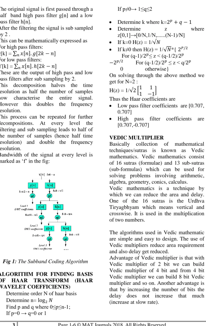
3 Page 1-6 © MAT Journals 2018. All Rights Reserved The original signal is first passed through a
half band high pass filter g[n] and a low pass filter h[n].
After the filtering the signal is sub sampled by 2 .
This can be mathematically expressed as For high pass filters:
y[k] = ∑ [ ] [ ]
For low pass filters: Y[k] = ∑ [ ] [ ]
These are the output of high pass and low pass filters after sub sampling by 2.
This decomposition halves the time resolution as half the number of samples now characterise the entire signal. However this doubles the frequency resolution.
This process can be repeated for further decompositions. At every level the filtering and sub sampling leads to half of the number of samples (hence half time resolution) and double the frequency resolution.
Bandwidth of the signal at every level is marked as ‘f’ in the fig:
Fig 1: The Subband Coding Algorithm ALGORITHM FOR FINDING BASIS OF HAAR TRANSFORM (HAAR WAVELET COEFFICIENTS)
Determine order N of haar basis
Determine n=
Find p and q where 0≤p≤n-1; If p 0 → q 0 or If p≠0→ ≤q≤2 Determine k where k= Determine z where [0 ]→[0 N N ... N-1)/N] If k=0 H(z) = 1/ If k≠0 then H *{ For (q-1)/ ≤ < q-1/2)/ For (q-1/2)/ ≤ < q 0 otherwise}
On solving through the above method we get for N=2 :
H(z) = 1/ *
+
Thus the Haar coefficients are
Low pass filter coefficients are [0.707, 0.707]
High pass filter coefficients are [0.707,-0.707]
VEDIC MULTIPLIER
Basically collection of mathematical techniques/sutras is known as Vedic mathematics. Vedic mathematics consist of 16 sutras (formulae) and 13 sub-sutras (sub-formulas) which can be used for solving problems involving arithmetic, algebra, geometry, conics, calculus.
Vedic mathematics is a technique by which we can reduce the area and delay. One of the 16 sutras is the Urdhva Tiryagbhyam which means vertical and crosswise. It is used in the multiplication of two numbers.
The algorithms used in Vedic mathematic are simple and easy to design. The use of Vedic multipliers reduce area requirement and also delay get reduced.
Advantage of Vedic multiplier is that with Vedic multiplier of 2 bit we can build Vedic multiplier of 4 bit and from 4 bit Vedic multiplier we can build 8 bit Vedic multiplier and so on. Another advantage is that by increasing the number of bits the delay does not increase that much (increase at slow rate).
4 Page 1-6 © MAT Journals 2018. All Rights Reserved URDHVA TRIYAKBHYAM
It is one of the 16 sutras of Vedic mathematics. This can be applied to integers, floating points and complex numbers. It can be used in both decimal and binary system. The number of operations performed in this is same as that to a conventional multiplication method but in this method the delay is less.
Fig2: Steps For 4 Bit Vedic Multiplication
CONVOLUTION
Linear Convolution is the basic operation to calculate the output for any linear time invariant system by its given input and its impulse response. Linear convolution can be calculated by different methods like graphical method, DFT-IDFT method, but all these methods require more calculation time and their design is complex and large area is needed.
Let two sequence be {a7a6 a5 a4 a3 a2 a1 a0} and {c7 c6 c5 c4 c3 c2 c1 c0}. Convolution result sequence is {d15 d14 d13 d12 d11 d10 d9 d8 d7 d6 d5 d4 d3 d2 d1}. Convolution is carried out by performing the multiplication operation. S
Fig 3: 8 bit linear convolution diagram a7 a6 a5 a4 a3 a2 a1 a0 * c7 c6 c5 c4 c3 c2 c1 c0__ a7c7 a7c6 a7c5 a7c4 a7c3 a7c2 a7c1 a7c0
a6c0 a5c0 a4c0 a3c0 a2c0 a1c0 a0c0 c7a6 c7a5 c7a4 c7a3 c7a2 c7a1 c7a0 c6a0
c5a0 c4a0 c3a0 c2a0 c1a0 a6c6 a6c5 a6c4 a6c3 a6c2 a6c1 a5c1 a4c1
a3c1 a2c1 a1c1
a6a5 c6a4 c6a3 c6a2 c6a1 c5a1 c4a1 c3a1 c2a1
a5c5 a5c4 a5c3 a5c2 a4c2 a3c2 a2c2 c5a4 c5a3 c5a2 c4a2 c3a2
a4c4 a4c3 a3c3 c4a3
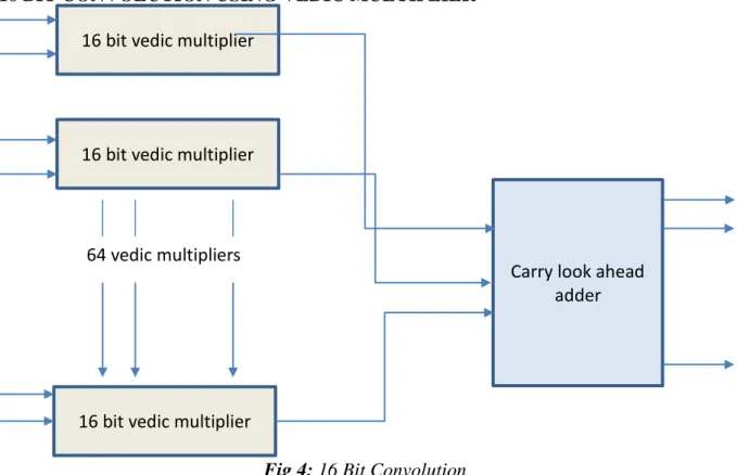
5 Page 1-6 © MAT Journals 2018. All Rights Reserved 16 BIT CONVOLUTION USING VEDIC MULTIPLIER
Fig 4: 16 Bit Convolution For the input sequence x[n] we have
considered 16 bit number plus one sign bit i.e. 8 bit (before the decimal point), 8 bit (after the decimal point) and one sign bit. When 16 bit is multiplied with 16 bit we obtain maximum output sequence to be of 32 bits and additional one sign bit. When
32 bits is added to 32 we obtain 33 bits along with one sign bit
In 16 bit convolution as shown in fig 3 there are 64 multipliers which are added through carry look ahead adder and we get 15 outputs as the result of 16 bit linear convolution.
CONCLUSION
Table1: Device Utilization Summary
Logic Utilization used Available Utilization
No. of slice registers 570 408000 0%
No. of slice LUTs 10315 204000 5%
No. of fully used LUT-FF pairs
558 10327 5%
No. of bonded IOBs 554 600 90%
BUFGS 6 32 18%
16 bit vedic multiplier
Carry look ahead adder 16 bit vedic multiplier
16 bit vedic multiplier 64 vedic multipliers
6 Page 1-6 © MAT Journals 2018. All Rights Reserved
Fig 5: Total Combinational Delay REFERENCES
1. Wavelet transform part 1 by ROBI POLIKAR.
2. Y. Bansal, C. Madhu and P. Kaur, "High speed vedic multiplier designs-A review," 2014 Recent designs-Advances in Engineering and Computational
Sciences (RAECS), Chandigarh, 2014,
pp. 1-6.
doi: 10.1109/RAECS.2014.6799502. 3. Design and analysis of 4x4 vedic
multiplier using carry save and vertical adder paper(Mat Journal Publication)