A Fully SDN Enabled All-Optical Architecture for
Data Centre Virtualisation with Time and Space
Multiplexing
K. Kondepu
1, C. Jackson
1, Y. Ou
1, A. Beldachi
1, A. Pag`es
2, F. Agraz
2, F. Moscatelli
3, W. Miao
4, V.
Kamchevska
5, N. Calabretta
4, G. Landi
3, S. Spadaro
2, S. Yan
1, D. Simeonidou
1, R. Nejabati
1Abstract—Virtual Data Centre (VDC) solutions provide an environment that is able to quickly scale-up and where virtual machines and network resources can be quickly added on-demand through self-service procedures. VDC providers must support multiple simultaneous tenants with isolated networks on the same physical substrate. The provider must make efficient use of their available physical resources whilst providing high bandwidth and low-latency connections to tenants with a variety of VDC configurations. This paper utilises state of the art optical network elements to provide high bandwidth optical interconnections and develop an VDC architecture to slice the network and the compute resources dynamically, to efficiently divide the physical network between tenants.
We present a Data Centre Virtualisation architecture with an SDN-controlled all-optical data plane combining Optical Circuit Switching (OCS) and Time Shared Optical Network (TSON). Developed network orchestration dynamically translates and provisions VDCs requests onto the optical physical layer. The experimental results show the provisioned bandwidth can be varied by adjusting the number of time slots allocated in the TDM network. These results lead to recommendations for provisioning TDM connections with different performance characteristics. Moreover, application level optical switch reconfiguration time is also evaluated to fully understand the impact on application performance in VDC provision. The experimental demonstration confirmed the developed VDC approach introduces negligible delay and complexity on the network side.
Index Terms—Virtual Data Centre; Optical Circuit Switching; Time Shared Optical Network; Multiplexing; Multi-Core Fibre; Software Defined Networking.
I. INTRODUCTION
D
EVELOPMENTS of worldwide Internet applications, big data and Internet of things (IoT) have been driving deployments of large-scale cloud data centers (DC), to further reduce the capital expenditure (CapEx) and operating expenses (OPEX) of DCs. According to the Cisco global cloud index 2016 [1], around 68 percent of cloud workloads will be carried in public cloud DCs by 2020 and more hyperscale DCs will be1
K. Kondepu, C. Jackson, Y. Ou, A. Beldachi, S. Yan, D. Simeonidou and R. Nejabati are with High Performance Networks Group (HPN), Univer-sity of Bristol, UK ({k.kondepu, c.jackson, a.beldachi, s.yan, d.simeonidou, r.nejabti}@bristol.ac.uk).
2
A. Pag`es, F. Agraz and S. Spadaro are with Universitat Politcnica de Catalunya, Barcelona, Spain ({albertpages, agraz, spadaro}@tsc.upc.edu).
3
F. Moscatelli and G. Landi are with Nextworks, Pisa, Italy ({f.moscatelli, g.landi}@nextworks.it).
4
W. Miao and N. Calabretta are with Technische Universiteit Eindhoven, Netherlands ({w.miao, N.Calabretta}@tue.nl).
5
V. Kamchevska is with Danmarks Tekniske Universiteit, Copenhagen, Denmark ([email protected]).
built. The hyperscale DCs offer massive computing resource and require more flexible and efficient network resource man-agements.
Data center virtualisation has been explored intensively to enable multi-tenant DCs in an on-demand manner [2]–[4]. Starting from simple server and storage virtualisations, DC industry is exploring DC virtualisations beyonds in application delivery, security abstraction, and network virtualisation for new avenues. A full data center network (DCN) virtualisation is highly desired to achieve flexible customisations of the Virtual DCs. Therefore, each tenant with heterogeneous band-width and topology requirements could be allocated an isolated slice of the underlying physical networking infrastructure. DC virtualisation offers a highly configurable, scalable and fully automated Infrastructure-as-a-Service (IaaS) method to manage computing, networking and storage resources in DCs. Recently, the emerged software-defined networking (SDN) and network function virtualisation (NFV) enable DC vir-tualisation to offer virtualised I/O, virtual desktop, unified communication virtualisation and so on [5], [6]. However, most studies focus on the traditional packet-based DC network architectures [7], [8]. A worth-noting trend is that optical switching technology will play a significant role for future hyperscale data centers [9], [10]. Optical circuit switching (OCS) and optical packet switching (OPS) technologies have been adopted incorporating the traditional electrical packet switching technology to offer the hybrid DC architectures [11], [12]. The diverse switching granularities from packets to circuits provide flexible bandwidth provisions [13], and on the other side rise more challenges for DC virtualisation. The unavailability of optical buffers leverages the difficulty to con-trol, configure and slice the high bandwidth and low latency optical interconnects [14]. [15] presents the orchestration and control architecture for VDC provisioning in multi-technology optical DCNs, essentially OCS and OPS. However, the paper main focus is in the network side of the provisioning, whereas in [16] the more dynamic scenario has been proposed by considering VM allocation, but not with specific computing resources. More recently, in [17], dynamic provision of both network and IT resource over geographically distributed data centers have been proposed to reduce operational expenses by consolidating virtual machines to maintain high CPU usage on the active servers.
This work is an extension of a previous work [18], where DC virtualisation with FPGA-based optical time-division
mul-detailed VDC provisioning of all-optical DCN virtualisation with TDM/PCS/SDM scheme. This work presents a fully DCN virtualisation implementation over an SDN enabled all-optical DCN architecture, including both the software im-plementation and the experimental demonstration. A detailed VDC provisioning strategy and implementation are elaborated based on the developed OpenStack platform on our proposed all-optical DC architecture. In addition, Orchestration mod-ule and the SDN controller modmod-ule are also developed to support the VDC implementation. The proposed all-optical DCN architecture is also explained as the base to support the virtualisation, to achieve flexible bandwidth provisions for the highly dynamic network traffic within the DCN. Moreover, the proposed architecture adopts both the optical TDM and the space-division multiplexing (SDM) in addition to the OCS technology. We have also added the performance of the low-level interconnection between the OpenStack compute nodes and optical devices with the traffic routing through a large-port-count fiber switch (LPFS) or OCS using OpenVSwitch. Furthermore, this paper also presents extended experimental setup using Hollow Core Fibres (HCFs) in the TDM data plane to show the impact of TDM scheme.
Here, the TDM network is achieved based on time-shared optical network (TSON) [19]. A beam-steering 2x2 4-core multi-core fibre (MCF) switch and the LPFS are deployed jointly to offer SDM with different granularities. The imple-mented DCN architecture employs the OpenDaylight SDN controller to provide the SDN-enabled DCN. SDN control of all network elements in this design provides a high degree of flexibility to support multi-tenancy. Meanwhile, a DC virtualisation architecture is proposed and implemented based on OpenStack platform to create and deploy the VDCs over the designed DCN. The virtualisation architecture enables a fine granular control of bandwidth and high connectivity provided by the optical network layer.
Finally, the DC virtualisation architecture is verified ex-perimentally on the developed optical testbed with a scalable physical layout, custom software modules, and the protocols developed to support the interfacing between the modules and the optical network devices. The detailed implementation of a fully software stack is reported including the orchestrator and the OpenFlow agents, which enable the provision of VDC instances over the novel optical data layer, that contains TSON and OCS elements. The intelligent orchestration layer dynamically provisions TDM slices or optical circuits to meet heterogeneous VDC bandwidth requirements on-demand. The performance of the DC virtualisation architecture is evaluated by comparing the link latency and the configuration time with SMFs or HCFs. The experimental demonstration confirmed the developed VDC approach introduces negligible delay and complexity on the network side.
The rest of this paper is organized as follows. Section II provides overall VDC provisioning architecture. Section III describes experimental setup and results. Finally, Section IV concludes the paper.
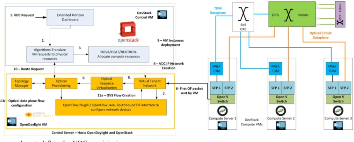
The VDC provisioning architecture is shown in Fig. 1. It consists of compute server nodes and one control node. The architecture utilises state of the art optical network elements to efficiently offer the physical network to multiple simultaneous tenants by slicing both computing and network resources. Each computing rack consists of three servers. An OpenStack compute virtual machine (VM) is deployed in each server, and is interfaced with both an optical time division multiplexing (OTDM) device and a high-radix Polatis LPFS switch. These two interfaces are referred to as the TSON and OCS networks respectively. Here, the LPFS is used to provide isolated optical circuits between servers, while the TDM network ensures that full connectivity can be maintained between servers within a rack.
The Data Plane consists of an LPFS-based OCS, above which the beam-steering 2x2 4-core MCF switch sits [10]. The MCF device offers a 300% increase in fibre capacity over the single-mode fibre (SMF) based device. Here, the MCF switch is used for inter-DC traffic. The two layers of OCS, combining with SMF and MCF devices (each controlled via SDN), en-able the flat DCN architecture with multi-granularities optical switching solutions. Additionally, there is a 4x4 optical fast switch (OXS) supporting broadcast with an FPGA controller that enables TDM switching and serves as a top of rack switch (TOR). Compute and storage nodes are interfaced to optical TDM using FPGA-based TDM Network Interface Cards (NICs) [9]. All the devices in the testbed are controlled via SDN. The fully SDN-controlled and orchestrated TSON and OCS dataplane enables granular bandwidth provisioning. Alongside MCF switching for inter-DC connectivity, there is a range of dataplane components to meet varied data path requirements.
The control node hosts VMs for the OpenStack controller and the SDN controller. It is connected to the compute nodes via an Electronic Packet Switched (EPS) management network. The two optical data networks enable flexible optical network provisioning to meet a variety of tenant requirements. The bespoke software modules deployed in this architecture are basically classified into two different lists, one for the orchestration and the second list corresponds to the SDN con-troller extension modules. The orchestration related modules are summarised as follows:
• Thedashboardis a web-based graphical interface, based on extensions to the OpenStack dashboard, to request the provisioning of VDC instances.
• VDC algorithmsmodule present in the orchestration layer is an important part for the vertical integration of the data plane and the control/management software as well as the whole VDC service provisioning. For a given VDC request, the algorithm module determines the mapping of the virtual machines and the corresponding virtual links that interconnect multiple virtual machines onto physical optical network node resources. To perform such action, the algorithms first receive a VDC petition coming from the OpenStack dashboard in the form of a Java Script Object Notation (JSON) file, which specifies the
Fig. 1. Architecture and control flow for VDC provisioning.
virtual topology of the VDC as well as the desired resources for both VMs and virtual links interconnecting them. Upon reception of the VDC request, the algo-rithm module collects resource availability regarding the servers and the optical resources from both OpenStack services and ODL controller. With such information and the details of the VDC request, the algorithm try to find the most suitable mapping of virtual resources onto physical ones. The algorithm is implemented based on the authors’ previous work on the mapping algorithm for pure OCS network [16], by expanding it to the hybrid TDM/OCS network. The OCS and TDM-based network resources requires the algorithm to choose the most suitable technology to realise the virtual links. Thus, we will detail the additional steps in this regard. For each virtual link, the required bandwidth is checked against the maximum capacity available through TDM connections. If the capacity is equal or lower, a TDM-based optical connection is provisioned for the virtual link. Otherwise, an OCS connection will be configured. For the first case, the number of TDM slots to fulfill the desired band-width is computed. Once found, a shortest path routing mechanism will run to find the optical path, constrained to TDM resources. Then, TDM slots are assigned in a first-fit fashion, guaranteeing both that assigned slots are free in the end-to-end route (slot continuity) and they can be assigned next to each other in the time domain (slot contiguity). If enough available slots meet these criteria, the connection is materialised. Otherwise, OCS resources may be employed as alternative. For the case of OCS resources, the algorithm checks if enough bandwidth is available at the optical channel to be employed. If so, a wavelength is assigned, following a first-fit procedure, with routing following a shortest-path routing, now con-strained to OCS resources. If enough available resources are found, the connection is materialised. Otherwise, the virtual link request is blocked and so is the VDC request, since all virtual links must be allocated to successfully satisfy the VDC. The procedure is summarised in pseudo-code of algorithm 1.
Additionally, it determines several logical instances (IP network, sub-network and ports) necessary to enable traffic exchange along the VDC instance. To enforce the mapping of the virtual machines and the creation of the
Algorithm 1 Actions for mapping virtual topology to the underlying physical resources
1: init
2: BT: Maximum bandwidth of TDM connection
3: BR: The requested connection bandwidth
4: BO: Maximum optical bandwidth
5: end init
6: Actions
7: if BR<=BT then
8: Compute TDM slots (S) required to fulfil the BR
9: if enough slots remaining on TDM connection and slot continuity and contiguity across the optical path is guaranteedthen
10: Allocate
11: else ifinsufficient slots then
12: Allocate optical channel
13: end if
14: else ifBR> BT then
15: Allocate optical channel
16: else ifBR> BO then
17: The requested connection bandwidth cannot fulfil!
18: end if
19: end Actions
logical resources, it interacts with the core orchestrator services thanks to the OpenStack Heat service. On the other hand, to enforce the physical network connectivity at the data plane, it interacts with the Optical Provisioning Manager (OPM) at the SDN controller to pass down the details of the route and the timeslots in the case that TDM technology is needed. The algorithm module has been extended to cope with the presence of new types of optical nodes in the topology (fast switch and optical NIC) as well as the server OVS nodes. Moreover, it has been extended to determine which is the most suitable technology, either fibre switching or TDM, to be employed to satisfy the bandwidth requirements of the virtual links. For the case of TDM, the algorithm module, besides the physical route and the necessary timeslots, also determines the particular VLAN to be employed when encapsulating the traffic of the virtual links. Thus, the optical NIC maps traffic onto a particular set of timeslots based on the VLAN tag of the said traffic.
of the stack (i.e., the collection of virtual resources, such as IP network and VMs) by contacting the Heat module of OpenStack, passing down a standard template containing the details of the resources to be deployed. The template sent from the algorithms contains both the VM placement and the IP network configuration of the VDC. Hence, the VM related information is used by the Nova module of the Orchestrator to deploy the IT infrastructure, and the network information is sent to the Controller by means of the Neutron module. The Controller receives the network creation request in its own Neutron module and forwards it to the Virtual tenant Network (VTN) module, which is the responsible for creating the IP network associated to the VDC and the virtual links that will interconnect the VMs. The orchestrator interaction with the SDN controller is described in [20].
A number of extensions were implemented for building the southbound interface of the SDN controller, which enables the inter-operability between the controller and the TMD data layer. The orchestrator and its extension algorithm module were also developed at the northbound. All the SDN controller extensions are briefly summarised as follows:
• An Optical Provisioning Manager software module co-ordinates the provisioning of DCN connections were implemented, which is based on the network paths com-puted by the algorithms. In our experimental scenario, the Optical Provisioning Manager is responsible for the configuration of (i) OVS instances in the hosts, (ii) optical NICs, (iii) the OXS TDM switch and (iv) the Polatis switch.
• Topology Manager software module is used to construct the DCN topology based on the advertisement of the data plane devices. Also, the topology manager is extended to support optical NICs and OXS TDM switches.
• Virtual Tenant Network modules handle the requests of virtual networks creation associated to a VDC. In particular, the Neutron module interfaces the orchestrator and the SDN controller, while the VTN configures the OVS instances of the compute nodes in the VDC to provide connectivities at L2/L3 levels.
• Optical Resource Virtualisation Manager software mod-ule is responsible for the virtualisation of optical devices; it mediates between the requests received from the or-chestrator (through the Neutron and VTN modules) and the requests of DCN connections issued to the Optical Provisioning Manager.
• OpenFlow Pluginmodule provides a layer of abstraction between the OpenFlow Java module and the model driven service abstraction layer (MD-SAL) components of the OpenDaylight Lithium (ODL). For example, it abstracts away OpenFlow versions to present a unified OpenFlow switch model above, hiding the detailed implementation changes between versions. It also provides inventory information to the controller with statistics on device flows and ports.
• OpenFlow Java (OpenFlow Library)provides the lowest
It is responsible for the (de-)serialisation of OpenFlow messages. Serialisation provides the function to translate the high-level MD-SAL Java objects to bytes.
OpenDaylight Lithium (ODL) was enhanced with a num-ber of novel extensions to support communications with the optical data plane elements. The OpenFlow (OF) protocol was extended to support the TSON and OCS devices. The extension includes the definition and modelling of the TDM scheme, as well as the development of TSON OF agents for the OXS and the FPGA NIC. The extensions of the protocol enabled the provisioning of optical resources in the data plane in combination with the orchestration layer.
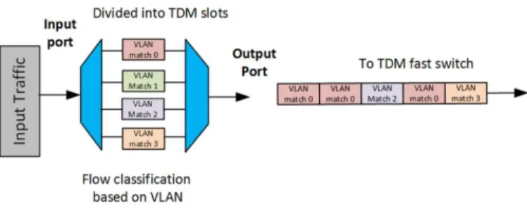
Fig. 2. TDM multiplexing on the FPGA TDM NIC based on VLAN ID
The orchestrator is an extended OpenStack (OSK) platform, in conjunction with an extended algorithms module to deploy VDCs onto the considered data plane architecture. The key upgrade to the algorithms module was to enable the selective allocation of TDM slices of complete circuits, depending on the requested bandwidth. The TDM scheme has configurable timeslot periods from 1-10µs, with the number of timeslots configurable from 4-96. When a VDC is configured, the bandwidth requirements of VMs are translated to the physical layer requirements used in Fig. 2. Based on VLAN IDs, the TDM multiplexing on the FPGA TDM NIC can configure both the mapping between the OXS input and the output, and the timeslots a TDM NIC may transmit. This is because, to multiplex the TDM slice, the FPGA NIC can only match on the VLAN ID, while not performing the desired matching of source-destination MAC addresses for a VDC network. Therefore, in Fig. 2, the compute OVS instances map VM sources and destination MAC addresses to VLANs so that each NIC can divide the allocated timeslots between different VNCs.
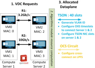
In Fig. 3, to optimise the provisioning of optical resources, a novel algorithm is used to translate tenants bandwidth requirements into the request for TDM slots or an optical circuit. This is an extended version of the previously charac-terised DC infrastructure [21]. In addition, the new algorithms module developed specifically for this architecture determines several logical instances (IP network, sub-network and ports) necessary to enable traffic exchange along the VDC instance as shown in Fig. 3. To map the VMs and create the logical resources, it interacts with the core orchestrator services via the OpenStack Heat service. As well as the physical route and the necessary timeslots, it also determines the particular VLAN to be employed when encapsulating the traffic of each
Fig. 3. Actions of the OVS instances on the OpenStack compute nodes to enable selective optical data plane usage
virtual link.
Fig. 4. Actions of the proposed algorithms module to allocate different data plane resources based on bandwidth request
When data enters the OVS at the source compute node, they are uniquely identified by the Source-Destination MAC addresses, and a VLAN ID is added to the packet header. This producer allows the TDM NIC to multiplex the incoming flows determined by the orchestration layer. When the multiplexed data arrives at the destination compute node, the VLAN ID is stripped (as shown in Fig. 4), and the packets again are forwarded by the associated MAC address. The flows to carry out these actions are calculated by the orchestrator and are programmed via ODL. The 96 timeslot granularity in this configuration allows the provisioning of virtual connections from 84 Mbps to 8.6 Gbps. This arrangement also creates the possibility to adapt dynamic circuit provisioning to bursts in traffic [22].
III. EXPERIMENTRESULTS
A. VDC Experimental Setup
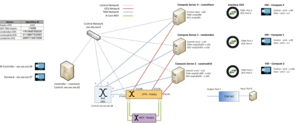
Figure. 5 illustrates the VDC experimental setup with re-spect to the architecture depicted in Fig. 1. The experimental setup utilises high-port count fibre switching devices, an optical TDM fast switch that performs the function of the delayed Venture fast switch, FPGA TDM NICs and MCF 4-core fibre switch.
The hardware control plane and the data plane are fully compatible with the extended ODL SDN controller for COSIGN project [23]. In addition, the extended ODL can be used by the extended OpenStack-based orchestration and control layers, in order to provision VDCs with dedicated optical circuits for achieving higher bandwidth requirements (>5 Gbps) as well as the varied lower-requirement TDM bandwidths (<5 Gbps). However, by varying the number of TDM slots assigned to a flow, sub-wavelength bandwidth division is also exploited in this experimental setup.
Figure. 5 also displays the location of various software en-tities deployed to enable the extended OpenStack orchestrator. The control node hosts a VM for the ODL and the OpenStack control instances individually. Each compute node contains a OpenStack compute VM. An OVS instance on the host enables the selective forwarding of flows to TDM or OCS paths. The use of a MCF switch above the LPFS enables the selection of the source and destination for the cores grouped within the fibres, adding a higher degree of flexibility. The MCF switching is intended to provide a high-bandwidth inter-data centre connectivity. For the purposes of experimentation, the MCF switch is fully connected to the LPFS.
The deployment of the VDC orchestrator and SDN con-troller for this setup uses two VMs running in a single physical server. The SDN controller is based on the OpenDaylight (extended), while the cloud orchestrator is based on the OpenStack controller (extended). In this particular setup, the Devstack based distribution of OpenStack has been adopted for the VDC deployment. The whole VDC infrastructure includes three OpenStack compute nodes, deployed as VMs, each of them running in a dedicated physical server with a TDM optical NIC connecting to the OXS TDM switch and a 10Gb NIC connecting to the LPFS (Polatis) switch. The connectivity between compute node and NICs on each physical server is mediated through an instance of Open Virtual Switch (OVS) running in the host, with bindings between the virtual bridge ports and the corresponding ports on the compute node VM and the physical NICs respectively as shown in Fig. 7.
Figure. 6 provides some insights about VDC resource configuration from both the orchestration and SDN-based controller. Figure. 6 shows the format of a VDC request as well as an example of server and optical path configuration as results of the VDC allocation algorithm to be enforced towards the data plane.
The VDC request takes the form of the JSON file, which includes a tree structure of the resources requested by the VDC tenant from the orchestrator dashboard. In essence, it is composed by a collection of virtual node objects identify-ing the VM flavor to be deployed (i.e., the VM computidentify-ing resources (CPUs, memory and storage)) as specified within OpenStack as well as the virtual links interconnecting the stated VMs, specifying the desired bandwidth in Mb/s. A Unique Universal Identifier (UUID) number following the OpenStack nomenclature is tied to each object as well as to the tenant requesting the VDC to enable their identification within the system.
The classification of the traffic in output from the physical servers is based on VLANs at the optical TDM NICs and on
Fig. 5. VDC Experimental Setup Configuration
Fig. 6. VDC request format
Fig. 7. Traffic Classification
the input port at the LPFS. Since OpenStack is configured with the flat network type, the traffic generated from the VMs and exiting from the OpenStack compute nodes is not tagged. For this reason, its classification at the OVS instances in the hosts is based on destination MAC addresses. In order to enable the proper classification of the traffic routing through the TDM path and in ingress to the optical NIC, a VLAN-based tagging
is performed at the OVS instances in the physical servers. The selection of the VLAN ID is decided by the VDC algorithms module in the cloud orchestrator, while the actual tagging and un-tagging is performed through OF actions defined in the rules configured by the SDN controller. The traffic routed through the LPFS or OCS based path is simply forwarded to the corresponding OVS output port and exits from the NIC connected to the LPFS switch without any change as shown in Fig. 7.
At the software level, both the orchestrator and ODL are deployed with the features developed for the VDC use case and with the plugins and algorithms required to operate over an heterogeneous DCN with includes L2 switches (represented by the OVS instances in the servers hosting the compute nodes), optical NICs, TDM-based switches and LPFS switches. The interaction between ODL and the data plane is based on the OF protocol. On the controller side, this is handled by an extended version of the OpenFlow plugin. In particular, the standard OpenFlow protocol is used for the configuration of the OVS instances, while support for fibre switching cross-connections and TDM-based resource allocation has been added for LPFS switches and optical NICs/OXS switches respectively.
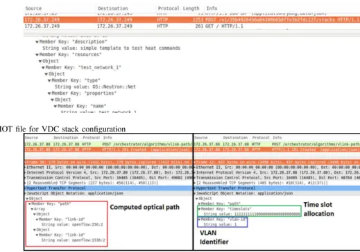
Once the algorithms have calculated the most suitable re-source mapping for the VDC (servers and optical connections), the desired configuration is enforced towards the data plane. In this regard, the process is mainly divided in two steps. First, the algorithms create a Heat Orchestration Template (HOT) file including all the resources (known as stack) to be deployed within OpenStack to satisfy the computational capabilities of the VDC as well as the creation of the IP network to enable data exchanges between VMs. In such template, it is possible to state the server in which a VM has to be deployed, passing as parameter the name/identifier of the server as tracked by OpenStack. In this way, the mapping of the VMs following the computations of the algorithms module is enforced. Figure. 8 depicts a wireshark capture showing an example of a HOT file resulting from the output of the algorithms module. This template is then processed by OpenStack services, which will result in the deployment of VMs onto servers and the configuration of the Layer3 IP network.
Second, to enable the data plane connectivity between servers, the algorithm module also passes the details of the
Fig. 8. Example of HOT file for VDC stack configuration
Fig. 9. Route details as passed by the Orchestrator to ODL controller for OCS (left) and TDM-based (right) optical technologies
route to be configured towards the ODL controller, that is, the sequence of optical links/ports to be configured, with the details of the TDM slots and the VLAN identifier to also be configured if the optical path requires to be configurator through TDM resources. These details are passed in the form of a JSON file towards the Path Computation Manager (PCM) at ODL, which will then translate them into concrete OpenFlow rules to be created at the corresponding optical nodes. Figure. 9 depicts a wireshark capture exemplifying the details of both types of considered routes: OCS (left) and TDM-based (right).
The performance of the circuit component of the data plane (the direct connections to the first layer LPFS) is well understood, providing a full 10 Gbps capacity and has been previously characterised and studied. Our testing was made up of the following components: (i) The TDM data plane was tested to establish throughput and latency characteristics for different TDM hardware configurations and software TDM slice (effectively bandwidth) allocations and allocation pat-terns. (ii) The effects of using Hollow Core Fibre (HCF) in the TDM data plane were investigated. (iii) The application-level reconfiguration latencies of the TDM switch and MCF switches were established.
B. Contiguous and interleaved timeslot allocation schemes
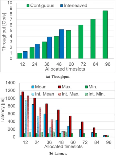
This section presents performance evaluation of TDM net-works by considering Contiguous and Interleaved timeslot allocation schemes. The performance of the TDM network was measured in terms of throughput and latency against allocated timeslots. As shown in Fig 5, the latency and throughput measurements are performed between the VM compute node 1 at server 1 (source) and the VM compute node 2 at server 2 (destination). The average value of latency and throughput measurements were obtained for considering ten passes. Figure. 10(a) demonstrate a sustainable maximum
data rate of up to 8.6 Gbps. As can be observed better throughput can be achieved with interleaved (or distributed) timeslots allocations. This is because interleaving scheme reduces the maximum delay between data transmissions. It is therefore recommended to avoid contiguous allocation for best performance. Similarly, Fig. 10(b) illustrates the maximum, minimum and mean latency measurements as function of al-located timeslots. The obtained maximum, minimum and mean latency measurements converge as timeslots increases because the largest gap between transmission timeslots reduces. The interleaved minimum is greater because unlike contiguous, there is always a no-transmit timeslot between transmissions.
C. HCF vs. SMF
Hollow Core Fibre (HCF) Photonic Band-Gap Fibre offers a 30% reduction in propagation delay when compared to Single Mode Fibre (SMF) [24]. The nature of TDM imposes relatively high latency on data transmission, due to the time taken to serialise data into a TDM frame slot which can be compensated using low propagation fibre. Hence, we aim to explore the extent to which the lower propagation delay of HCF affects the behaviour of the TDM network in terms of both throughput and latency. Figure 11 shows the experimental setup evaluation to compare HCF and SMF connections with FGPA TDM NIC cards. We connected two servers using FPGA TDM NICs and two standard optical NICs to evaluate the impact of HCF on the optical TDM plane. The two servers are not represented in the figure as they are racked servers but the setup of two servers are similar to one it is shown in Fig 7. The standard NICs can be recognised by the operating system (OS) and enable application-layer traffic to be transmitted over the TDM network.
We measure throughput and latency of the TDM connec-tion with a range of slot allocaconnec-tions and patterns with both SMF and HCF. We used 100m of SMF vs 100m of HCF
(a) Throughput.
(b) Latency.
Fig. 10. Throughput and Latency measurements for contiguous and inter-leaved allocated timeslots.
Fig. 11. Experimental setup for comparing HCF and SMF performance in the TDM-based data plane.
on the TDM NIC. The bandwidth of the TDM network is configurable at the hardware layer by altering the ratio of real data transmitted to key characters and so we obtain results for different bandwidths. In addition, the TDM scheme exposed to the application layer enables provisioning of fractions of the hardware-configured bandwidth. As show in the Fig. 11, Anritsu traffic analyzers (MD1230B) were used to configure the different TDM slot allocations.
The TDM scheme allows a variable number of slots to be utilised for transmission. With the optimal configuration the
LATENCIES FOR THE VARIOUS COMPONENTS IN THETDMEXPERIMENTS.
SMF HC-PBGF
Propagation delay 5 ns/m 3.5 ns/m Latency over 10m fibre 50ns 35ns Latency over 100m fibre 500ns 350+5ns1
Latency over NIC-NIC
direct connection without TDM with 100m fibre 8140ns 8030ns Average latency with TDM over 100m fibre
(maximum bandwidth) 50036ns 41664ns Minimum latency with TDM over 100m fibre
(maximum bandwidth) 41427ns 34162ns Maximum latency with TDM over 100m fibre
(maximum bandwidth) 57153ns 48540ns
peak throughput attainable is 8.6 Gbps. To establish if the lower latency of HCF could affect the timeslot-to-throughput settings, we measured the bandwidth over the 96 possible timeslots with IP traffic. A fibre length of 100 m was used for each plus a 1 m patch fibre APC to LC conversion for the SFP+ connection. The test configurations are shown in Table. I.
As can be observed in Fig. 12(a) there is no noticeable effect on throughput when using the HCF. Each allows the TDM con-nection to achieve the maximum theoretical throughput when the full timeslot allocation is used. Using HCF should offer improvements in latency characteristics. As TDM schemes incur additional latency when slicing data into timeslots, it is possible that HCF can help alleviate some of this latency penalty. Again we took multiple measurements with different timeslot allocations. The maximum, minimum and average latencies are presented.
As can be observed from Fig. 12(b) HCF exhibits lower maximum, minimum and average latencies. The nearly flat results at 96 timeslots are caused because all transmit timeslots are full. The other timeslot allocations have several slots during which no data is transmitted, incurring a latency penalty. However, the data in Table. I shows us that even with 100m of fibre, by far the largest component of latency is contributed by the buffering and logic of the FPGA TDM NIC. We observe the greatest percentage latency saving when all timeslots are utilised, this is because we have removed another source of latency-a timeslot in which data is not transmitted.
We attempted to improve on the previous performance mea-surements. It is clear from the Fig. 10(b) and Fig. 12(b) that when all timeslots are utilized the latency behavior changes significantly and that empty (no-transmit) timeslots contribute a significant fraction of latency. Therefore, we repeated our experiments by interleaving timeslots instead of allocating them in a contiguous block. In the experiment this means that only half the slots can be utilized, but two or more applications could run concurrently with interleaved timeslots provisioned by the orchestration layer.
For the same number of timeslots, we show the change in throughput when using interleaved instead of contiguous allocation in Fig. 13(a) It is clear that identical throughput increases can be obtained regardless of the fibre type. There-fore, the latency of the link does not affect the throughput of
(a) Throughput.
(b) Latency.
Fig. 12. Throughput and Latency measurements for HCF and SMF fibre with different timeslot allocations.
the TDM scheme. However, we examine the latency changes also. From the Fig. 12(b), we would expect that change in latency will differ for the different fibre types. In Fig. 13(b) we observe improvements in average latency readings across the spectrum of timeslots. The allocated timeslots occupy a greater area of the TDM frame, thus reducing average latency. However, overall the average latency improvements are greater for SMF than HCF.
A switching latency of the MCF was measured at appli-cation level. Using a ping-flood method we attempted to de-termine the effective reconfiguration time from an application perspective. Figure. 14 shows the successful evaluation switch reconfiguration by (un)install of flow. The switch reconfigu-ration time is defined as the time elapsing between the last address resolution packet (ARP) request and the detection of the corresponding ARP response message. The switch recon-figuration time is measured the mean reconrecon-figuration time of the MCF switch over five iterations as121µs. In addition, the
switching latency of the OXS was measured at both the circuit and application level. The time taken to switch an input from one output to another was measured electronically as25nsat
the circuit level [25]. Similarly, the OXS switching time using a ping-flood method to determine the effective reconfiguration
(a) Throughput improvement.
(b) Latency improvement.
Fig. 13. Throughput and Latency using interleaved timeslots allocations.
time from an application perspective is measured. The mean value was measured over five reconfigurations includes the end-to-end buffering and serialisation for the TSON scheme at38.7µs. The detailed description of frame exchange between
the Agent and the FPGA controller while (un)installing flow frames is described in [26].
Fig. 14. Application Level MCF Switching Time
Compared to the same measurement with the NIC in Ether-net mode of 8.3µs, we identify an overhead of 30.1µs [27] when using the extra buffering, logic and negotiation (key characters) involved in the TSON implementation. These results demonstrate that circuit-level measurements alone are insufficient to understand the performance impact of reconfig-uration on the software network stack.
IV. CONCLUSIONS
In this paper, the VDC provisioning scheme was success-fully implemented on the all-optical data plane capable of
full fibre connections. The approach to building the optical data plane holds a significant promise when size and energy consumption prevents scaling up using legacy approaches. A complete software stack from orchestrator-to-OpenFlow agents to enable VDCs on an all-optical data layer is successfully demonstrated. Circuit and TSON switching are combined to offer flexible and granular bandwidth provisioning. Our results allow us to make recommendations for provisioning TDM connections with different performance characteristics. Inter-DC traffic or very high bandwidth inter-cluster traffic is supported with a MCF switch connected to the high-radix LPFS backplane. We compared circuit-level switch reconfigu-ration time with that observed from the application level and notice a significant increase. This demonstrates that signal-level measurements alone are insufficient for VDC architects and providers to fully understand the impact on application performance of optical switch reconfiguration times. The mea-sured reconfiguration times at these different levels differ by orders of magnitude.
ACKNOWLEDGMENT
This work is supported by ECFP7 grant no. 619572, the COSIGN project (www.fp7-cosign.eu).
REFERENCES
[1] “Cisco Global Cloud Index:Forecast and Methodology,2015-2020.” [On-line]. Available: http://www.cisco.com/c/dam/en/us/solutions/collateral/ service-provider/global-cloud-index-gci/white-paper-c11-738085.pdf [2] “Interoute Virtual Data Centre. Hands on cloud control.” [Online].
Avail-able: https://www.interoute.com/sites/default/files/product-instance/file-attachments/VDC Brochure UK 190214 ONLINE.pdf
[3] M. F. Bari, R. Boutaba, R. Esteves, L. Z. Granville, M. Podlesny, M. G. Rabbani, Q. Zhang, and M. F. Zhani, “Data Center Network Virtualization: A Survey,” vol. 15, no. 2, pp. 909–928, Second 2013. [4] G. Ghoda, N. Meruliya, D. H. Parekh, T. Gajjar, D. Dave, and
R. Sridaran, “A survey on data center network virtualization,” in2016 3rd International Conference on Computing for Sustainable Global Development (INDIACom), pp. 3464–3470.
[5] M. Gharbaoui, B. Martini, D. Adami, G. Antichi, S. Giordano, and P. Castoldi, “On virtualization-aware traffic engineering in OpenFlow Data Centers networks,” in2014 IEEE Network Operations and Man-agement Symposium (NOMS), pp. 1–8.
[6] R. Krishnan, T. Hinrichs, D. Krishnawamy, and R. Krishnaswamy, “Policy-based monitoring and energy management for NFV Data Cen-ters,” in 2015 International Conference on Computing and Network Communications (CoCoNet), pp. 10–17.
[7] D. Cho, J. Taheri, A. Y. Zomaya, and L. Wang, “Virtual Network Function Placement: Towards Minimizing Network Latency and Lead Time,” in 2017 IEEE International Conference on Cloud Computing Technology and Science (CloudCom), pp. 90–97.
[8] K. Jeong, R. Figueiredo, and K. Ichikawa, “PARES: Packet Rewriting on SDN-Enabled Edge Switches for Network Virtualization in Multi-Tenant Cloud Data Centers,” in2017 IEEE 10th International Conference on Cloud Computing (CLOUD), pp. 9–17.
[9] S. Yan, E. Hugues-Salas, V. J. F. Rancaˇno, Y. Shu, G. M. Saridis, B. R. Rofoee, Y. Yan, A. Peters, S. Jain, T. May-Smith, P. Petropoulos, D. J. Richardson, G. Zervas, and D. Simeonidou, “Archon: A function programmable optical interconnect architecture for transparent intra and inter data center sdm/tdm/wdm networking,”Journal of Lightwave Technology, vol. 33, no. 8, pp. 1586–1595, April 2015.
[10] H. C. H. Mulvad, A. Parker, B. King, D. Smith, M. Kovacs, S. Jain, J. R. Hayes, M. Petrovich, D. J. Richardson, and N. Parsons, “Beam-steering all-optical switch for multi-core fibers,” inOptical Fiber Communication Conference. Optical Society of America, 2017, p. Tu2C.4.
V. Subramanya, Y. Fainman, G. Papen, and A. Vahdat, “Helios: A hybrid electrical/optical switch architecture for modular data centers,” vol. 41, no. 4, pp. 339–350, 00215. [Online]. Available: http://dl.acm.org/citation.cfm?id=1851223
[12] K. Chen, A. Singla, A. Singh, K. Ramachandran, L. Xu, Y. Zhang, X. Wen, and Y. Chen, “OSA: An Optical Switching Architecture for Data Center Networks With Unprecedented Flexibility,” vol. 22, no. 2, pp. 498–511, 00000.
[13] K. Christodoulopoulos, K. Kontodimas, A. Siokis, K. Yiannopoulos, and E. Varvarigos, “Efficient bandwidth allocation in the NEPHELE optical/electrical datacenter interconnect,” vol. 9, no. 12, pp. 1145–1160. [14] C. R. Jackson, R. Nejabati, F. Agraz, A. Pag`es, M. Galili, S. Spadaro, and D. E. Simeonidou, “Demonstration of the benefits of sdn technology for all-optical data centre virtualisation,” in Optical Fiber Communication Conference. Optical Society of America, 2017, p. Tu3L.3.
[15] S. Spadaro, A. Pags, F. Agraz, R. Montero, and J. Perell, “Orchestrated sdn-based vdc provisioning over multi-technology optical data centre networks,” in2017 19th International Conference on Transparent Op-tical Networks (ICTON), July 2017, pp. 1–4.
[16] S. Spadaro, A. Pag`es, F. Agraz, R. Montero, and J. Perell, “Resource orchestration in SDN-based future optical data centres,” in2016 Interna-tional Conference on Optical Network Design and Modeling (ONDM), May 2016, pp. 1–6.
[17] Y. Shen, P. Samadi, and K. Bergman, “Autonomous network and IT Resource Management for Geographically Distributed Data Centers,”
IEEE/OSA Journal of Optical Communications and Networking, vol. 10, no. 2, pp. A225–A231, Feb 2018.
[18] C. Jackson, K. Kondepu, Y. Ou, A. Beldachi, A. Pag`es, F. Agraz, F. Moscatelli, W. Miao, V. Kamchevska, N. Calabretta, G. Landi, S. Spadaro, R. Nejabati, and D. Simeonidou, “COSIGN: A Complete SDN Enabled All-Optical Architecture for Data Centre Virtualisation with Time and Space Multiplexing,” in ECOC 2017; 43rd European Conference on Optical Communication, Sept 2017, pp. 1–3.
[19] Y. Yan, Y. Qin, G. Zervas, B. Rahimzadeh Rofoee, and D. Simeonidou, “High Performance and Flexible FPGA-Based Time Shared Optical Network (TSON) Metro Node,” inEuropean Conference and Exhibition on Optical Communication, ser. OSA Technical Digest (online). Optical Society of America, p. We.3.D.6. [Online]. Available: http: //www.opticsinfobase.org/abstract.cfm?URI=ECEOC-2012-We.3.D.6 [20] “COSGIN Project Deliverable D4.3: COSIGN orchestrator interaction
with the COSIGN SDN controller platform.” [Online]. Available: http://www.fp7-cosign.eu/
[21] A. Pages, F. Agraz, R. Montero, G. Landi, R. Monno, J. I. Aznar, A. Vines, C. Jackson, D. Simeonidou, and S. Spadaro, “Experimental assessment of vdc provisioning in sdn/openstack-based dc infrastructures with optical dcn,” inECOC 2016; 42nd European Conference on Optical Communication, Sept 2016, pp. 1–3.
[22] Y. Ben-Itzhak, C. Caba, L. Schour, and S. Vargaftik, “C-share: Op-tical circuits sharing for software-defined data-centers,” CoRR, vol. abs/1609.04521, 2016.
[23] “COSIGN:Combing Optics and SDN In next Generation data centre Networks.” [Online]. Available: http://www.fp7-cosign.eu/
[24] F. Poletti, N. V. Wheeler, M. N. Petrovich, N. Baddela, E. Numkam Fok-oua, J. R. Hayes, D. R. Gray, Z. Li, R. Slavk, and D. J. Richardson, “Towards high-capacity fibre-optic communications at the speed of light in vacuum,”Nature Photonics, vol. 10.1038/nphoton.2013.45, 2013. [25] N. Calabretta, K. Williams, and H. Dorren, “Monolithically integrated
wdm cross-connect switch for nanoseconds wavelength, space, and time switching,” inECOC 2015; 41st European Conference on Optical Communication, Sept 2015, pp. 1–3.
[26] “COSGIN Project Deliverable D2.1: Integration of OpenFlow SW Interface with POLATIS System and Venture 4x4 OXS.” [Online]. Available: http://www.fp7-cosign.eu/
[27] K. Kondepu, J. Zou, A. F. Beldachi, H. K. Chen, C. Chase, M. Huang, E. H. Salas, J. A. Garcia-Espin, A. Tzanakaki, R. Nejabati, M. Eiselt, and D. Simeonidou, “Performance evaluation of next-generation elastic backhaul with flexible vcsel-based wdm fronthaul,” inECOC 2017; 43rd European Conference on Optical Communication, Sept 2017, pp. 1–3.