For
Business-Critical Continuity™
Liebert Mini-Mate2
™
I
MPORTANTS
AFETYI
NSTRUCTIONS. . . .1
P
RODUCTN
UMBERN
OMENCLATURE. . . .3
1.0
I
NTRODUCTION. . . .6
1.1
Designed to Match Computer and Electronic Equipment Needs—From Installation
to Operation . . . 6
2.0
S
TANDARDF
EATURES—2 & 3 T
ONS
YSTEMS. . . .7
2.1
Evaporator Section - Split Systems . . . 7
2.2
Condensing Unit Section—Split Systems . . . 7
2.2.1 Indoor Centrifugal Fan Condensing Units . . . 7
2.2.2 Outdoor Prop Fan Condensing Units . . . 7
2.2.3 Indoor Water/Glycol Condensing Units. . . 7
2.3
Chilled Water Units . . . 7
2.4
System Controls . . . 8
2.4.1 Other Standard Control Features . . . 8
3.0
O
PTIONALF
ACTORY-I
NSTALLEDF
EATURES—E
VAPORATOR/C
HILLEDW
ATERU
NITS. . . .9
3.1
Reheat . . . 9
3.2
Humidifier. . . 9
3.3
Sensors . . . 9
3.4
Switches and Motors . . . 9
3.5
Free-Cooling . . . 10
3.6
Optional Configurations—Prop Fan Condensing Units. . . 10
3.7
Optional Configurations—Water/Glycol Condensing Units . . . 10
3.8
Optional Configurations—Chilled Water Units . . . 10
4.0
S
HIP-L
OOSEA
CCESSORIES—F
IELD-I
NSTALLED. . . 11
4.1
Remote Monitoring, Autochangeover and Leak Detection Equipment. . . 12
5.0
S
ITEP
REPARATIONANDI
NSTALLATION. . . .13
5.1
Installation Considerations . . . 13
5.1.1 System Configurations . . . 13
5.1.2 Room Preparation. . . 14
5.1.3 Location Considerations. . . 14
5.2
Ceiling Unit Weights . . . 16
5.3
Equipment Inspection—Upon Receipt . . . 16
5.4
Packaging Material . . . 16
5.5
Installing the Ceiling Units . . . 16
5.5.1 Close-Coupled Installations . . . 17
5.5.2 Evaporator Air Distribution. . . 17
5.5.3 Piping Connections and Coolant Requirements . . . 18
5.5.4 Condensate Pump Kit Installation—All Units . . . 27
5.6
Indoor Air-Cooled Centrifugal Fan Condensing Unit Installation . . . 30
5.6.1 Location Considerations. . . 30
5.6.2 Electrical Connections . . . 30
5.6.3 Piping Connections. . . 31
5.6.4 Ducting . . . 31
5.7
Outdoor Air Cooled Condensing Unit Installation . . . 34
5.7.1 Location Considerations. . . 34
5.7.2 Piping Connections. . . 35
5.7.3 Electrical Connections . . . 35
5.8
Water and Glycol Cooled Condensing Unit. . . 36
5.8.1 Location Considerations. . . 36
5.8.2 Electrical Connections . . . 38
5.8.3 Piping Connections. . . 38
5.9
Optional Equipment Piping . . . 40
5.9.1 Free-Cooling Coil . . . 40
5.9.2 Hot Water Reheat Coil . . . 41
5.10
Checklist for Completed Installation . . . 42
6.0
M
ICROPROCESSORC
ONTROL. . . .43
6.1
Feature Overview . . . 43
6.2
Main Menu <Menu>. . . 44
6.3
Setpoints . . . 44
6.4
Status . . . 45
6.5
Active Alarms . . . 45
6.6
Time. . . 45
6.7
Date . . . 45
6.8
Setback . . . 45
6.9
Setup Operation . . . 46
6.9.1 Restart Time Delay. . . 46
6.9.2 C/F Degrees. . . 46
6.9.3 Humidity Control Method . . . 46
6.10
Change Passwords . . . 46
6.11
Calibrate Sensors . . . 47
6.12
Alarm Enable . . . 47
6.13
Alarm Time Delay . . . 47
6.14
Common Alarm Enable . . . 47
6.15
Custom Alarms . . . 48
6.15.1 Standard Custom Alarm Messages . . . 48
6.16
Custom Text . . . 48
6.17
Run Diagnostics (Available On Rev 1.001.0 and Higher) . . . 50
7.2.1 Dehumidification/Humidification Required . . . 55
7.2.2 Dehumidification Operation, Compressorized Direct Expansion (DX) Systems . . . 55
7.2.3 Humidification Operation . . . 55
7.3
Load Control Features . . . 55
7.3.1 Communication. . . 55
8.0
A
LARMS. . . .56
8.1
Standard Alarms: Definitions and Troubleshooting . . . 56
8.1.1 Custom Alarms . . . 56
8.1.2 High Head Pressure . . . 56
8.1.3 Humidity Level . . . 57
8.1.4 Temperature . . . 57
8.1.5 Humidifier Problem Alarm . . . 57
8.1.6 High Water Alarm . . . 57
8.1.7 Loss of Power . . . 57
8.1.8 Short Cycle . . . 58
8.2
Optional/Custom Alarms . . . 58
8.2.1 Change Filter . . . 58
8.2.2 High Temperature Sensor . . . 58
8.2.3 Smoke Detected . . . 58
9.0
S
YSTEMT
ESTINGANDM
AINTENANCE. . . .59
9.1
System Testing . . . 59
9.1.1 Environmental Control Functions. . . 59
9.1.2 Cooling. . . 59
9.1.3 Heating . . . 59
9.1.4 Humidification . . . 59
9.1.5 Dehumidification . . . 59
9.1.6 High Temperature Sensor—Optional . . . 59
9.1.7 Smoke Detector Sensor . . . 59
9.1.8 Remote Shutdown. . . 59
9.2
Maintenance . . . 60
9.2.1 Electric Panel . . . 60
9.2.2 Filters . . . 60
9.2.3 Direct Drive Blower Package . . . 60
9.2.4 High Static Belt Drive Blower Package (Option) . . . 61
9.2.5 Refrigeration System . . . 61
9.2.6 Humidifier Circuit Board Adjustments. . . 64
9.3
Replacement Procedures . . . 65
9.3.1 Compressor Replacement. . . 65
9.3.2 Electrical Failure . . . 66
9.3.3 Replacing the Humidifier Canister . . . 67
10.0 M
AINTENANCEI
NSPECTIONC
HECKLIST. . . .68
FIGURES
Figure 1 Model number nomenclature—Evaporator units . . . 3
Figure 2 Model number nomenclature—Air-cooled, indoor condensing units . . . 3
Figure 3 Model number nomenclature—Outdoor air-cooled prop fan condensing units . . . 4
Figure 4 Model number nomenclature—Water/glycol-cooled condensing units. . . 4
Figure 5 Model number nomenclature—Chilled water units . . . 5
Figure 6 Wall-box. . . 8
Figure 7 Free-cooling arrangement. . . 10
Figure 8 Air-cooled systems, 2 and 3 tons . . . 15
Figure 9 Water/glycol-cooled systems, 2 and 3 tons. . . 15
Figure 10 Chilled water systems, 3 tons. . . 15
Figure 11 Threaded rod and hardware kit installation . . . 17
Figure 12 Refrigerant piping diagram . . . 21
Figure 13 Dimensions, evaporator and chilled water units with direct drive blower . . . 24
Figure 14 Dimensions, evaporator units with optional belt drive blower assembly . . . 25
Figure 15 Evaporator and chilled water unit piping data . . . 26
Figure 16 Evaporator and chilled water unit electrical connections . . . 29
Figure 17 Close-coupled installation. . . 30
Figure 18 Indoor air-cooled centrifugal condenser dimensions and pipe connections . . . 32
Figure 19 Centrifugal condenser electrical connections . . . 33
Figure 20 Cabinet and floor planning dimensional data, outdoor condensing unit. . . 34
Figure 21 General arrangement (air- cooled condensing unit) . . . 36
Figure 22 Cabinet dimensions and piping data, water/glycol indoor condensing module. . . 37
Figure 23 General arrangement, water/glycol split systems. . . 39
Figure 24 Optional free-cooling coil (3-way valve) on water/glycol units . . . 40
Figure 25 Optional hot water reheat (two-way valve) . . . 41
Figure 26 Control key locations—all-mounted display box . . . 43
Figure 27 Control menu. . . 51
Figure 28 Control board (inside evaporator) . . . 52
Figure 29 Wall box board. . . 52
Figure 30 Ground current detector . . . 54
Table 1 System configurations - 60Hz. . . 13
Table 2 System configurations - 50Hz. . . 13
Table 3 Application limits, evaporator and chilled water units* . . . 13
Table 4 Application limits, indoor and outdoor air-cooled condensing units . . . 13
Table 5 Application limits, indoor water/glycol-cooled condensing units . . . 13
Table 6 Ceiling unit weights . . . 16
Table 7 Cooling unit air flow at 0.3 IWG (75PA) ESP . . . 18
Table 8 Recommended refrigerant line sizes . . . 22
Table 9 Pipe length and condenser elevation relative to evaporator . . . 22
Table 10 Line charges - refrigerant per 100 ft. (30m) of Type L copper tube . . . 22
Table 11 Refrigerant charge in Liebert pre-charged R-407C line sets . . . 22
Table 12 Equivalent lengths for various pipe fittings, ft (m). . . 22
Table 13 Refrigerant charge . . . 23
Table 14 Connection sizes and torque. . . 23
Table 15 Net weights—evaporator and chilled water units . . . 24
Table 16 Net weight, high static blower module . . . 25
Table 17 Indoor condensing unit airflow, CFM at 0.5 iwg esp . . . 31
Table 18 Centrifugal condenser dimensions, weights . . . 32
Table 19 Dimensions and net weights—air-cooled outdoor condensing units . . . 35
Table 20 Net weight, indoor water/glycol-cooled condensing unit. . . 37
Table 21 View default setpoints and allowable ranges . . . 44
Table 22 Microprocessor night and weekend setback . . . 45
Table 23 Setup functions, default values and allowable ranges . . . 46
Table 24 Alarm default time delays . . . 47
Table 25 Switch settings (wall box board) . . . 49
Table 26 Equipment switch settings (unit control board) . . . 49
Table 27 Cooling and dehumidification load response of hot gas bypass . . . 53
Table 28 External static pressure available . . . 61
Table 29 Typical discharge pressure . . . 61
Table 30 DIP switch settings for humidifier control board (2- and 3-ton unit . . . 65
I
MPORTANT
S
AFETY
I
NSTRUCTIONS
SAVE THESE INSTRUCTIONS
This manual contains important safety instructions that should be followed during the installation and maintenance of the Liebert Mini-Mate2. Read this manual thoroughly before attempting to install or operate this unit. Only qualified personnel should move, install or service this equipment. Adhere to all warnings, cautions and installation, operating and safety instructions on the unit and in this manual. Follow all installation, operation and maintenance instructions and all applicable local and national building, electrical and plumbing codes.
!
WARNING
Arc flash and electric shock hazard. Disconnect all electric power supplies and wear protective equipment per NFPA 70E before working within electric control enclosure. Failure to comply can cause serious injury or death.Customer must provide earth ground to unit, per NEC, CEC and local codes, as applicable. Before proceeding with installation, read all instructions, verify that all the parts are included and check the nameplate to be sure the voltage matches available utility power.
The Liebert microprocessor control does not isolate power from the unit, even in the Unit Off mode. Some internal components require and receive power even during the Unit Off mode. The line side of the disconnect switch on the front of the unit contains live high-voltage. The only way to ensure that there is NO voltage inside the unit is to install and open a remote disconnect switch and check the internal power supply wires with a voltmeter. Refer to unit electrical schematic. Follow all applicable local and national electric codes.
!
WARNING
Risk of explosive discharge from high-pressure refrigerant. Can cause injury or death.This unit contains fluids and gases under high pressure. Relieve pressure before working with piping.
!
WARNING
Risk of refrigerant system rupture or explosion from overpressurization. Can cause equipment damage, injury or death.If a pressure relief device is not provided with the condenser unit, the system installer must provide and install a discharge pressure relief valve per local and national codes in the high side refrigerant circuit. Do not install a shutoff valve between the compressor and the field installed relief valve. Do not isolate any refrigerant circuits from overpressurization protection.
!
WARNING
Risk of high-speed moving parts. Can cause injury or death.Open all local and remote electrical power disconnect switches before working in the unit and component electrical enclosures.
!
CAUTION
Risk of contact with hot surfaces. Can cause injury.The compressors, refrigerant discharge lines, humidifiers and reheats are extremely hot during unit operation. Allow sufficient time for them to cool before working within the unit cabinet. Use extreme caution and wear protective gloves and arm protection when working on or near hot compressors, discharge lines, humidifiers and reheats.
Important Safety Instructions
NOTICE
Risk of a leaking coil due to freezing and/or corrosion. Can cause equipment and serious building damage.
Cooling coils and piping systems that are connected to open cooling towers or other open water/glycol systems are at high risk for freezing and premature corrosion. Fluids in these systems must contain the proper antifreeze and inhibitors to prevent freezing and premature coil corrosion. The water or water/glycol solution must be analyzed by a competent water treatment specialist before startup to establish the inhibitor requirement. The water or water/glycol solution must be analyzed every six months to determine the pattern of inhibitor depletion. The complexity of water-caused problems and their correction makes it important to obtain the advice of a water treatment specialist and follow a regularly scheduled
maintenance program.
NOTICE
Risk of damage from forklift. Can cause unit damage.
Keep tines of the forklift level and at a height suitable to fit below the skid and/or unit to prevent exterior and/or underside damage.
NOTICE
Risk of improper storage. Can cause unit damage.
Keep the Liebert Mini-Mate2 upright, indoors and protected from dampness, freezing temperatures and contact damage.
!
CAUTION
Risk of leaking water. Can cause equipment and building damage.This unit requires a water drain connection. It may also require an external water supply to operate. Improper installation, application and service practice can result in water leakage from the unit. Water leakage can result in severe property damage and loss of critical data center equipment. Do not locate unit directly above any equipment that could sustain water damage. Emerson recommends installing leak detection equipment for unit and supply lines and in the secondary drain pan. Check drain lines periodically for leaks, sediment buildup, obstructions, kinks and/or damage and verify that they are free running.
!
CAUTION
Risk of sharp edges, splinters and exposed fasteners. Can cause injury.Only properly trained and qualified personnel wearing appropriate safety headgear, gloves, shoes and glasses should attempt to move the unit, lift it, remove packaging from or prepare the unit for installation.
P
RODUCT
N
UMBER
N
OMENCLATURE
Figure 1 Model number nomenclature—Evaporator units
Figure 2 Model number nomenclature—Air-cooled, indoor condensing units
MM
D = Disconnect Switch 0 = No Disconnect Switch MM = Liebert Mini-Mate2 Refrigerant 7 = R-407CD
36
7
A
H
A
Blower Type D = Direct Drive Internal Blower B = Belt Drive External Blower Supply Power P = 208/230V - 1 ph - 60Hz X = 277V - 1 ph - 60Hz S = 220V - 1 ph - 50Hz (3-ton only) A = 460V - 3 ph - 60Hz (3-ton only) Y = 208/230V - 3 ph - 60Hz (3-ton only) M = 380/415V - 3ph - 50Hz (3-ton only)E
Unit Type E = Split EvaporatorK = Split Evaporator with Free-Cooling
E
D
Humidification
H = Canister Humidifier 0 = No Humidifier
R = Remote Humidifier Contact J = Canister Humidifier and Remote
Humidifier Contact Reheat Type 0 = No Reheat E = Electric Reheat
S = SCR Reheat (not available with free-cooling) Sensor Packages 0 = None A = Filter Clog B = Smoke Sensor C = High-Temperature Sensor D = Filter Clog & Smoke Sensor
E = Filter Clog & High-Temperature Sensor F = Smoke Sensor & High-Temperature Sensor
G = Filter Clog, Smoke Sensor & High-Temperature Sensor Nominal Capacity
MC
D = Disconnect Switch 0 = No Disconnect Switch
MC = Liebert Mini-Mate2 indoor condensing units
Refrigerant 7 = R-407C
H = Hot Gas Bypass
D
36
L
A
H
7
Head Pressure Controls
L = Liebert Lee-Temp™ Receiver
Supply Power P = 208/230V - 1 ph - 60Hz X = 277V - 1 ph - 60Hz S = 220V - 1 ph - 50Hz (3-ton only) A = 460V - 3 ph - 60Hz (3-ton only) Y = 208/230V - 3 ph - 60Hz (3-ton only) M = 380/415V - 3ph - 50Hz (3-ton only)
A
Cooling Method A = Air-Cooled Nominal Capacity 24 = 2-ton, 60Hz 35 = 3-ton, 50Hz 36 = 3-ton, 60HzProduct Number Nomenclature
Figure 3 Model number nomenclature—Outdoor air-cooled prop fan condensing units
Figure 4 Model number nomenclature—Water/glycol-cooled condensing units
PFH
Nominal Capacity, kBtuh PF = Prop Fan Condensing Unit with Hot Gas Bypass
P = 208/230V - 1ph - 60Hz Y = 208/230V - 3ph - 60Hz (3-ton only) A = 460V - 3ph - 60Hz (3-ton only) B = 575V - 3ph - 60Hz (3-ton only) S = 220V - 1ph - 50Hz (3-ton only) M = 380/415V - 3ph - 50Hz (3-ton only)
0
37
A
P
L
7
L = 95°F Ambient, Liebert Lee-Temp™ H = 105°F High Ambient, Liebert Lee-Temp 0 = Std. Sound Level Z = Quiet-Line — = Standard Coil C = Coated Coil Cooling Method A = Air-Cooled Refrigerant 7 = R-407C—
MC
D = Disconnect Switch 0 = No Disconnect Switch MC = Liebert Mini-Mate2 indoor condensing units Refrigerant 7 = R-407C H = Hot Gas BypassD
38
2
A
H
7
Head Pressure Controls
2 = 2-Way Standard Pressure Water Reg Valve 3 = 3-Way Standard Pressure Water Reg Valve D = 2-Way High-Pressure Water Reg Valve T = 3-Way High-Pressure Water Reg Valve
Supply Power P = 208/230V - 1 ph - 60Hz X = 277V - 1ph - 60Hz S = 220V - 1ph - 50Hz (3-ton only) A = 460V - 3ph - 60Hz (3-ton only) Y = 208/230V - 3ph - 60Hz (3-ton only) M = 380/415V – 3ph-50Hz (3-ton only)
W
Cooling Method W = Water/Glycol Nominal Capacity 26 = 2-ton, 60Hz 37 = 3-ton, 50Hz 38 = 3-ton, 60HzFigure 5 Model number nomenclature—Chilled water units
MM
D = Disconnect Switch 0 = No Disconnect Switch MM = Liebert Mini-Mate2 Blower TypeD = Direct Drive Internal Blower B = Belt Drive External Blower
Reheat Type 0 = No Reheat E = Electric Reheat H = Hot Water Reheat
D
40
C
3
A
H
E
Cooling Method C = Chilled Water Nominal Capacity 39 = 3-ton, 50Hz 40 = 3-ton, 60HzA
D
Valve Type2 = 2-Way Chilled Water Valve 3 = 3-Way Chilled Water Valve
Supply Power P = 208/230V - 1 ph - 60Hz X = 277V - 1ph - 60Hz S = 220V - 1ph - 50Hz A = 460V - 3ph - 60Hz Y = 208/230V - 3ph - 60Hz M = 380/415V – 3ph-50Hz Humidification H = Canister Humidifier 0 = No Humidifier
R = Remote Humidifier Contact J = Canister Humidifier and Remote
Humidifier Contact Sensor Packages 0 = None
A = Filter Clog B = Smoke Sensor
C = High-Temperature Sensor D = Filter Clog & Smoke Sensor E = Filter Clog & High-Temperature
Sensor
F = Smoke Sensor & High Temperature Sensor
G = Filter Clog, Smoke Sensor & High-Temperature Sensor
Introduction
1.0
I
NTRODUCTION
1.1
Designed to Match Computer and Electronic Equipment Needs—From Installation
to Operation
Installed above the ceiling, Liebert Mini-Mate2 Precision Cooling systems control the cooling, humidity and air distribution required by sensitive electronic equipment. A range of sizes and configurations is available to meet varying sites’ needs.
The Liebert Mini-Mate2 is also easy to use. Advanced microprocessor technology allows easy, precise control, and menu-driven monitoring keeps you informed of system operation through the LCD readout. These features, combined with Emerson quality construction and reliable components, guarantee satisfaction from installation through operation.
Liebert Precision Cooling
Liebert Precision Cooling systems are designed to control the environment required for computers and other sensitive electronic equipment. The Liebert Mini-Mate2 provides complete control on an around-the-clock basis and the high sensible heat ratio required by sensitive electronic equipment.
Easy Installation
The Liebert Mini-Mate2 is a split-system evaporator combined with an air-, water- or glycol-cooled condensing unit or is a self-contained, chilled water unit. Each split system has thermostat-type wiring to controls and condensing unit. System components are pre-charged with refrigerant and can be connected together with optional pre-charged line sets or optional sweat adapters for field
refrigerant piping.
Easy to Service
Low-maintenance components are easily accessed through removable front panels. Spare parts are always in Emerson inventory and available on short notice.
Advanced Control Technology
A menu-driven microprocessor control system provides precise temperature and humidity control and accurate alarm setpoints. Using touch-sensitive buttons, the wall-mounted monitor/control panel allows you to select and display temperature and other monitored parameters.
High Efficiency
High sensible heat ratio, scroll compressor and precise microprocessor control allow the system to operate efficiently.
Space Saving Design
All indoor components are installed above the ceiling, so no floor space is required.
Reliable
The Liebert Mini-Mate2 family installed base is a testimony to the system reliability. Components include a rugged scroll compressor, high-efficiency copper tube, aluminum-fin evaporator coil and a double inlet, direct drive fan.
Agency Listed
Standard 60Hz units are CSA certified to the harmonized U.S. and Canadian product safety standard, CSA C22.2 No 236/UL 1995 for “Heating and Cooling Equipment” and are marked with the CSA c-us logo.
Location
When considering installation locations, consider that these units contain water and that water leaks can cause damage to sensitive equipment
2.0
S
TANDARD
F
EATURES
—2 & 3 T
ON
S
YSTEMS
2.1
Evaporator Section - Split Systems
The evaporator section is designed for ceiling installation. The cabinet and chassis are constructed of heavy gauge galvanized steel. The unit can be serviced using only one side increasing its versatility in mounting locations. Mounting brackets are factory-attached to the cabinet. Internal cabinet
insulation meets ASHRAE 62.1 requirements for Mold Growth, Humidity & Erosion, tested per UL 181 and ASTM 1338 standards.
The evaporator section includes the evaporator coil, R-407C unit charge, filter-drier, factory-mounted disconnect switch, two-speed direct-drive blower assembly and microprocessor control with wall-mounted control box. The unit is provided with supply and return air openings for field-supplied ducting or supply/return plenum. Evaporators can be configured with canister humidifier and/or reheat. An indoor or outdoor condensing unit must be selected for each evaporator.
2.2
Condensing Unit Section—Split Systems
2.2.1 Indoor Centrifugal Fan Condensing Units
Indoor Air-Cooled Centrifugal Fan Condensing Units include scroll compressor, factory-mounted disconnect switch, condenser coil, R-407C unit charge, belt-driven centrifugal blower assembly, high-pressure switch, Liebert Lee-Temp™ head pressure control system, hot gas bypass and
liquid-line solenoid valve. Unit must be mounted indoors. Condensing unit is designed to use outdoor air with temperatures ranging from -30°F to 95°F (-34°C to 35°C).
2.2.2 Outdoor Prop Fan Condensing Units
Outdoor Prop Fan Condensing Units include scroll compressor, condenser coil, R-407C unit charge, prop fan, liquid-line solenoid valve, high pressure switch, Liebert Lee-Temp head pressure control and hot gas bypass. Condensing unit is designed for outdoor locations with operating ambients ranging from -30°F to 95°F (-34°C to 35°C).
2.2.3 Indoor Water/Glycol Condensing Units
Indoor Water/Glycol Condensing Units includes scroll compressor, R-407C unit charge, factory-mounted disconnect, coaxial condenser, hot gas bypass, high head pressure switch and two-way water regulating valve designed for 150psi (1034.3kPa). Condensing units can be used on either a water or glycol cooling loop.
2.3
Chilled Water Units
Chilled Water Units are designed for ceiling installation. The cabinet and chassis are constructed of heavy gauge galvanized steel. The unit can be serviced using only one side increasing its versatility in mounting locations. Mounting brackets are factory-attached to the cabinet. Internal cabinet
insulation meets ASHRAE 62.1 requirements for Mold Growth, Humidity & Erosion, tested per UL 181 and ASTM 1338 standards. Chilled water models are self-contained and include a chilled water coil, speed, direct-drive centrifugal blower, factory-mounted disconnect switch and two-way, slow-close motorized valve. Design pressure is 300psi (2068kPa), 60psi (414kPa) close-off differential.
Standard Features—2 & 3 Ton Systems
2.4
System Controls
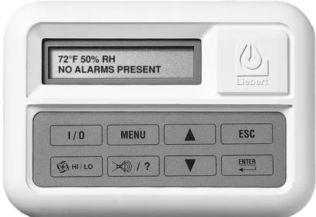
System controls include a microprocessor control board mounted in the evaporator/chilled water unit and a wall-mounted interface with a two-line, 16-character liquid crystal display. An eight-key, membrane keypad for setpoint/program control, unit On/Off, fan speed and alarm silence is below the LCD screen. It provides temperature setpoint and sensitivity adjustment, humidity setpoint and sensitivity adjustment, digital display of temperature, humidity, setpoints, sensitivities, fan speed and alarm conditions.
The wall-box is field-wired to the microprocessor control using standard four-conductor thermostat wire (field-supplied). The temperature and humidity sensors are in the wall box, which can be installed up to 300 feet (91.4m) from the evaporator unit. The unit-mounted control board also includes common alarm terminals and shutdown terminals. The unit automatically restarts after a power outage.
Figure 6 Wall-box
2.4.1 Other Standard Control Features
• Adjustable auto restart • Calibrate sensors
• 5 day/2 day setback • Predictive humidity control • Password protection • Common alarm output • Alarm enable/disable • Remote shutdown terminals • Self-diagnostics
3.0
O
PTIONAL
F
ACTORY
-I
NSTALLED
F
EATURES
—E
VAPORATOR
/C
HILLED
W
ATER
U
NITS
3.1
Reheat
Electric Reheat includes 304/304 stainless steel finned tubular reheat elements, with high limit safety switch.
SCR Electric Reheat uses an SCR controller and unit control software to provide full cooling with modulating of the electric reheat elements to control air temperatures. Reheat capacity is up-sized to offset the cooling capacity. (The SCR Electric Reheat is not available on chilled water, free-cooling or 575V units.)
Hot Water Reheat includes hot water coil, 2-way solenoid valve and Y-strainer.
3.2
Humidifier
The Canister Humidifier includes a steam-generating type humidifier with automatic flushing circuit, inlet strainer, drain, 1" (25.4mm) air gap on fill line and solenoid valves. Humidifier problem alarm annunciates at the wall-mounted display panel.
Remote Humidifier Contact allows the unit’s humidity controller to control a humidifier outside the unit. Power to operate the remote humidifier does not come from the Liebert Mini-Mate2. Available on units with or without internal humidifier.
3.3
Sensors
Smoke Sensor checks return air, shuts down the unit upon sensing smoke and activates visual and audible alarms at the wall-box display. This smoke sensor is not intended to function as or replace any smoke sensor system that may be required by local or national codes.
High-Temperature Sensor senses the return air temperature and shuts down unit if the
temperature reaches 125°F (52°C). This device is not meant to replace any fire detection system that may be required by local or national codes.
3.4
Switches and Motors
Filter Clog senses pressure drop across the filters and activates visual and audible alarms at the wall-box display. The wall-box display annunciates the alarm and flashes a notification upon reaching a customer setpoint.
A Factory-Installed Non-Fused Disconnect Switch allows unit to be turned off for maintenance. A disconnect switch is standard for the evaporators, chilled water units and indoor condensing units, but these units may be specified without the switch.
Direct-Drive blower can be factory-eliminated from the evaporator/chilled water cabinet for high static applications (0.9 to 1.5in. [23 to 38mm] w.g.). See 4.0 - Ship-Loose Accessories—Field-Installed for the optional, externally mounted high static blower assembly.
NOTE
Optional Factory-Installed Features—Evaporator/Chilled Water Units
3.5
Free-Cooling
Free-cooling option includes separate cooling coil, three-way slow-close valve and separate supply and return piping. Free-cooling is activated when the water temperature reaches a field-adjustable temperature, typically 45°F (7°C). The valve is rated for 300psi (2068kPa) working pressure. Air-cooled condensing units can be matched with evaporators using free-cooling coils with chilled water sources to serve as backup cooling. When matched with a water/glycol condensing unit, a three-way water regulating valve is recommended for the condensing unit to simplify piping to the main supply pipes. The coil is designed for closed-loop applications using properly treated and circulated fluid. Not available with SCR reheat options.
Figure 7 Free-cooling arrangement
3.6
Optional Configurations—Prop Fan Condensing Units
Outdoor Prop Fan Condensing Units are also available in the following optional configurations: • High ambient models for providing catalog capacities at ambient temperatures up to 105°F
(40°C).
• Quiet-Line models for low noise level conditions (below 56 dBA) and for providing catalog capacities at ambient temperatures up to 95°F (35°C).
• Condenser coils can be phenolic-coated for extended coil life in coastal areas.
3.7
Optional Configurations—Water/Glycol Condensing Units
Indoor Water/Glycol Condensing Units are also available with the following piping options: • Two-way water reg. valve with 350 psi (2413kPa) design pressure.
• Three-way water reg. valve with 150psi (1034kPa) design pressure. NOTE
If free-cooling is applied to an open water tower, an optional copper-nickel (CuNi) coil is required to prevent premature corrosion, or a heat exchanger must separate the tower water from the free-cooling loop. The copper-nickel coil requires an extended lead time.
Free -Cooling Coil Water/Glycol Condenser Field Piping Water Temperature Sensor Liebert Mini-Mate2 Drycooler
Free-cooling option: A second cooling coil allows the system to take advantage of colder outdoor
temperatures and bypass compressor operation.
When the water temperature goes below 45°F (7°C), cooling switches over to free-cooling operation. A separate chilled water source can also be used with air-cooled systems.
4.0
S
HIP
-L
OOSE
A
CCESSORIES
—F
IELD
-I
NSTALLED
A High Static Blower Assembly can be field-attached to the evaporator to provide up to 2.0" (51mm) of external static pressure on the discharge side of the evaporator. The blower box contains a centrifugal-type double-inlet blower. This blower is equipped with a belt drive and 1.5 hp single speed motor mounted to an adjustable motor base. Note: Unit must be ordered without the internal direct drive motor and the high static blower disables the two-speed fan operation feature.
Filter box kit (for ducted applications) includes filter box with duct flange connection, one MERV 8 (ASHRAE 52.2-2007) filter (20"x20"x4" [508mm x 508mm x 102mm]), and a duct flange for use on the supply air opening of the unit
Air Distribution Plenum includes molded plastic three-way discharge plenum, 16"x25"x4"
(406mm x 535mm x 102mm) MERV 8 filter (ASHRAE 52.2-2007), and sheet metal block-off plates for covering the duct openings on the evaporator unit. Plenum mounting requires T-bar ceiling grid. The Condensate Pump is field-mounted external to the cabinet, wired to the unit power block and is equipped with a check valve. A secondary float can be field-wired to shut down the unit upon high condensate level.
A Remote Temperature and Humidity Sensor package includes sensors in an attractive case with 30 ft. (9 m) of cable. Can be wall or duct mounted. Remote sensors should be used when the wall box is not located in the space to be conditioned.
Field-Installed Kits available for filter clog, smoke sensor, high-temperature sensor, electric reheat and humidifier. The kits include installation instructions and are designed to be added to the
evaporator unit before it is installed in the ceiling. Electric reheat kits cannot be installed in units with free-cooling.
277-to-208V step-down transformer (37.5 amps) allows use of 277-1-60 supply power with a 208-1-60 Prop Fan Condensing unit. The transformer is coated with epoxy and contained in an enclosed, non-ventilated electrical box with adaptable mounting brackets.
Single-Point Power Kit contains the necessary electrical components to interconnect the high-voltage sections of a close-coupled evaporator and an MCD condensing unit.
Pre-Charged Refrigerant Line Set (R-407C) contains an insulated copper suction line and a copper liquid line for interconnection of the indoor and outdoor sections. Available in 15-foot (4.5m) and 30-foot (9m) sections.
The Refrigerant-Line Sweat Adapter Kit contains two suction and two liquid line fittings that allow field-supplied refrigerant piping between the evaporator and condensing unit.
NOTE
Ship-Loose Accessories—Field-Installed
4.1
Remote Monitoring, Autochangeover and Leak Detection Equipment
The Liebert RCM4™is a four-point, normally open, dry contact monitoring panel. One Form-C, dry contact common alarm relay output (rated at 24 VAC, 3 Amp) is provided. Four red LEDs illuminate on the respective alarm and the alarm buzzer is silenced by a front panel switch. The RCM4 requires a 24VAC or 24VDC power source. Power supply is not included.
The Liebert AC4™ Autochangeover Controller provides autochangeover and autosequence control for up to four Liebert Mini-Mate2 units within a room. The Liebert AC4 will enable redundant units in an alarm condition, balance usage and test standby units at programmed intervals. Two common alarm relay outputs are available. A built-in LCD and RS-232 port for direct PC/terminal connection provides two options for configuration and monitoring of the product. The Liebert AC4 requires 24VAC input power.
The Liebert AC8™ is ideal for coordinated control of systems with redundant units. The Liebert AC8 enables redundant devices during an alarm condition, balances usage of devices and tests standby devices at programmable intervals. Supports four zones and can use the 4-20mA temperature sensor (TW420) for temperature staging in each zone. Two programmable output control relays are available for auxiliary control such as humidity lockout. Emergency power operation input provided for device control during an emergency. Two common alarm relay outputs are available. A built-in LCD and RS-232 port for direct PC/terminal connection provides two options for configuration and monitoring of the product.
The Liebert ENV-DO™ interface card provides 16 discrete outputs, corresponding to status and major alarm conditions of Environmental units. The Liebert ENV-DO-ENCL1 packages one
Environmental DO interface card in its own steel enclosure and the ENV-DO-ENCL2 packages two Environmental DO interface cards in one enclosure for installation external to the Liebert
Mini-Mate2. The self-contained kit includes an external 120VAC-to-24VAC power transformer. Wiring harnesses are not provided. Power and communication wiring is field-provided.
The Liebert Liqui-tect® 410 Point Leak Detection Sensor detects the presence of conductive liquid using a pair of corrosion-resistant, gold-plated probes mounted in a painted, height-adjustable enclosure. Dual Form-C, dry contact common alarm relays (rated at 24VAC, 3A) signal a leak detected as well as loss of power and cable fault. The Liebert Liqui-tect 410 requires an external 24VAC or 24VDC power source.
Liebert LT460 Zone Leak Detection Kits include one LT460 sensor, a specified length of
LT500-xxY cable (maximum length is 100 ft [30.5m]) and a corresponding number of hold-down clips. The Liebert LT460 requires an external 24VAC, 0.12A power source, such as EXT-XFMR or XFMR24. Liebert SiteScan® is a monitoring solution that gives you decision-making power to effectively manage the equipment critical to your business.
Liebert SiteScan enables communication from Liebert environmental and power units, as well as many other pieces of analog or digital equipment, to a front-end software package that provides real-time status and alarms so you can react quickly to changing situations.
Liebert SiteScan is designed with flexibility for both small systems and large, complex systems such as those in computer rooms, telecommunications facilities or industrial process control rooms. Contact your local Emerson representative for assistance with a Liebert SiteScan system.
The NIC-ENCL1 and NIC-ENCL2 package one or two Liebert IntelliSlot® Web/485 Cards with
Adapters, respectively, in one steel enclosure for installation external to the Liebert Mini-Mate2. The Liebert IntelliSlot Web/485 Card with Adapter provides communication with the Liebert
Mini-Mate2™ via SNMP, HTTP, RTU Modbus 485 and BACnet IP. The self-contained kit includes an
external 120VAC-to-24VAC transformer as a power source. Wiring harnesses are not provided. Power and communication wiring are field-provided.
5.0
S
ITE
P
REPARATION
AND
I
NSTALLATION
5.1
Installation Considerations
The evaporator unit is usually mounted above the suspended ceiling of the space to be conditioned. Ducted systems may be installed in a different room.
5.1.1 System Configurations
The typical system configuration has a separate evaporator or cooling unit and a condensing unit. Chilled water systems are self-contained units. Refer to Tables 1 and2 and to Figures 8,9 and10 for different system combinations and unit configurations that are possible.
NOTE
Before installing unit, determine whether any building alterations are required to run piping, wiring and ductwork. Carefully follow all unit dimensional drawings and refer to the
submittal engineering dimensional drawings of individual units for proper clearances.
Table 1 System configurations - 60Hz
Nominal
Capacity CoolingUnit
Condensing Unit Indoor Air-Cooled
Centrifugal fan Outdoor Air-CooledPropeller Fan Water/GlycolIndoor
2 Tons MM_24E MC_24A PFH_27A MC_26W
3 Tons MM_36E MC_36A PFH_37A MC_38W
MM_40C Self-Contained - Chilled Water
Table 2 System configurations - 50Hz
Nominal
Capacity CoolingUnit
Condensing Unit Indoor Air-Cooled
Centrifugal fan Outdoor Air-Cooled Propeller Fan Water/Glycol-CooledIndoor Remote
3 Tons MM_35E MC_35A PFH_36A MC_37W
MM_39C Self-Contained - Chilled Water
Table 3 Application limits, evaporator and chilled water units*
Input Voltage Range of Return Air Conditions to Unit Minimum Maximum Dry Bulb Temperature Relative Humidity
-5% +10% 65°F to 85°F (18°C to 29°C) 20% to 80%
* Unit will operate at these conditions but will not control to these extremes of conditions.
Table 4 Application limits, indoor and outdoor air-cooled condensing units
Input Voltage
Condensing Units
Entering Dry Bulb Air Temperature
Minimum Maximum Minimum Maximum
-5% +10%
Outdoor Prop Fan Condensing Unit
-30°F (-34°C)
115°F (46°C) standard unit* 125°F (52°C) high ambient unit* Indoor Air-Cooled
Condensing Unit 115°F (46°C)*
* Unit capacity ratings are stated for 95°F (35°C) for standard units and 105°F (41°C) for high ambient PFH units only. Exceeding these rating points by 20°F (11°C) will result in lower cooling capacities, but will not damage the equipment.
Table 5 Application limits, indoor water/glycol-cooled condensing units
Input Voltage Entering Fluid Temperature
Minimum Maximum Minimum Maximum
-5% +10% 65°F (18.3°C) * 115°F (46°C)
Site Preparation and Installation
5.1.2 Room Preparation
The room should be well insulated and must have a sealed vapor barrier. The vapor barrier in the ceiling and walls can be a polyethylene film. Paint on concrete walls and floors should contain either rubber or plastic.
Outside or fresh air should be kept to a minimum when tight temperature and humidity control is required. Outside air adds to the cooling, heating, dehumidifying and humidifying loads of the site. Doors should be properly sealed to minimize leaks and should not contain ventilation grilles.
5.1.3 Location Considerations
Install the evaporator unit over an unobstructed floor space if possible. This will allow easy access for routine maintenance or service. Do not attach additional devices (such as smoke detectors, etc.) to the housing, as they could interfere with the maintenance or service.
When using the optional air distribution plenum, avoid locating the evaporator unit in confined areas that affect the air flow pattern. Such locations could cause short cycles, downdrafts and air noise. Avoid locating the unit in an alcove or at the extreme end of a long, narrow room. Avoid installing multiple units close to each other. This could result in crossing air patterns, uneven loads and competing operating modes.
When installing an air-cooled or water/glycol-cooled unit inside a space, ensure that national and local codes are met for refrigerant concentration limits that might vary with building type and use.
NOTE
The single most important requirement for maintaining environmental control in the conditioned room is the vapor barrier.
!
CAUTION
Risk of leaking water/glycol. Can cause building and equipment damage.Do not mount units over equipment and furniture that can be damaged by leaking
water/glycol. Install a watertight drain pan with a drain connection under the cooling unit and water/glycol condenser unit. Route the drain to a frequently used maintenance sink so that running water can be observed and reported in a timely manner. Post a sign to alert people to report water flowing from the secondary drain pan.
NOTE
Do not mount units in areas where normal unit operating sound may disturb the working environment.
NOTE
Temperature and humidity sensors are in the wall box. Install the wall box where discharge air DOES NOT blow directly on the sensors.
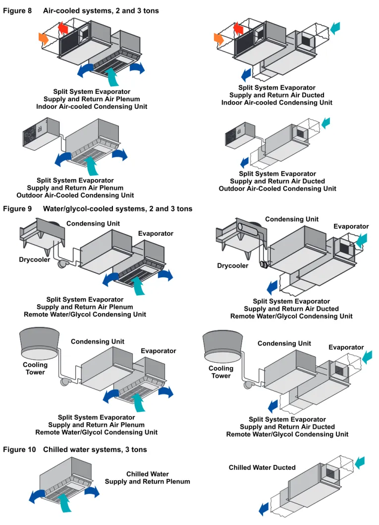
Figure 8 Air-cooled systems, 2 and 3 tons
Figure 9 Water/glycol-cooled systems, 2 and 3 tons
Figure 10 Chilled water systems, 3 tons
Split System Evaporator Supply and Return Air Plenum Indoor Air-cooled Condensing Unit
Split System Evaporator Supply and Return Air Ducted Indoor Air-cooled Condensing Unit
Split System Evaporator Supply and Return Air Plenum Outdoor Air-Cooled Condensing Unit
Split System Evaporator Supply and Return Air Ducted Outdoor Air-Cooled Condensing Unit
Split System Evaporator Supply and Return Air Ducted Remote Water/Glycol Condensing Unit Split System Evaporator
Supply and Return Air Plenum Remote Water/Glycol Condensing Unit
Split System Evaporator Supply and Return Air Ducted Remote Water/Glycol Condensing Unit
Condensing Unit Evaporator Drycooler Condensing Unit Evaporator Drycooler Condensing Unit
Evaporator Condensing Unit Evaporator
Cooling Tower
Split System Evaporator Supply and Return Air Plenum Remote Water/Glycol Condensing Unit Cooling
Tower
Chilled Water Supply and Return Plenum
Site Preparation and Installation
5.2
Ceiling Unit Weights
5.3
Equipment Inspection—Upon Receipt
When the unit arrives, do not uncrate equipment until it is close to its final location. All required assemblies are banded and shipped in corrugated containers. If you discover any damage when you uncrate the unit, report it to the shipper immediately. If you later find any concealed damaged, report it to the shipper and to your Liebert supplier.
5.4
Packaging Material
All material used to package this unit is recyclable. Save it for future use or dispose of the material appropriately.
5.5
Installing the Ceiling Units
The evaporator unit and condensing unit are usually mounted above the ceiling and must be securely mounted to the roof structure. The ceiling and ceiling supports of existing buildings may require reinforcements. Be sure to follow all applicable national and local codes. Use field-supplied threaded suspension rods and 3/8-16 factory hardware kit.
Recommended clearance between ceiling grids and building structural members is unit height plus
Table 6 Ceiling unit weights
Model # Weightlb (kg) Cooling Units * MMD24E 225 (102) MMD35E 225 (102) MMD36E 225 (102) MMD39C 230 (104) MMD40C 230 (104) Indoor Condensing Units
MCD24A 270 (125) MCD35A 280 (130) MCD36A 280 (130) MCD26W 190 (90) MCD37W 200 (95) MCD38W 200 (95) MCD38W 200 (95)
* Add 20 lb. (9kg) to units with free-cooling or hot water reheat coils.
!
WARNING
Risk of ceiling collapse and heavy unit falling. Can cause building and equipment damage, serious injury or death.Verify that the supporting roof structure is capable of supporting the weight of the unit(s) and the accessories. (see 5.2 - Ceiling Unit Weights.)
Using a suitable lifting device that is rated for the weight of the unit (see 5.2 - Ceiling Unit Weights), raise the unit and pass the threaded rods through the four mounting holes in the flanges that are part of the unit base.
Attach the threaded rods to the unit flanges using the supplied nuts and grommets. (See Figure 11). The rubber grommets provide vibration isolation.
1. First, use the plain nuts to hold unit in place. Adjust these nuts so that the weight of the unit is supported evenly by the four rods, does not rest on the ceiling grid, and to ensure the unit is level.
2. Second, use the shake-proof nuts to “jam” the plain nuts.
Figure 11 Threaded rod and hardware kit installation
5.5.1 Close-Coupled Installations
If the evaporator and indoor condensing units are to be mounted back-to-back (close-coupled), hang each unit before connecting them together. Align four bolt holes in the condensing unit with cage nuts in the evaporator. Insert rubber spacers and secure with provided hardware. Align the refrigerant connections and tighten them as described in 5.5.3 - Piping Connections and Coolant
Requirements (see Figure 17).
Close-coupled installations may take advantage of a single-point power kit to allow one power feed to provide input for both evaporator and condensing units. Kit should be mounted in evaporator unit before raising unit into ceiling area.
5.5.2 Evaporator Air Distribution
Filter Box
The optional filter box is available for the unit and mounts directly to the return air opening of the evaporator. The 2 and 3 ton filter box is supplied with a MERV 8 filter (per ASHRAE 52.2-2007) measuring 20 in. x 20 in. x 4 in. (508x508x102mm).
NOTE
The units must be level in order to drain condensate properly.
3/8" Threaded Rod (field-supplied) 3/8" Hex Nut 3/8" Washer Sleeve Isolator 3/8" Fender Washer 3/8" Hex Nut 3/8" Hex Nut Nylock
Site Preparation and Installation
Plenum Installation
The 2- and 3-ton non-ducted evaporators can use the optional ceiling-mounted plenum to provide four-way air distribution. The plenum fastens to the bottom of the evaporator. The plenum includes a 16 in. x 25 in x 4 in (406x635x102mm) MERV 8 filter (per ASHRAE 52.2-2007).
1. The evaporator should be mounted above the bottom of the T-bar supports with at least 30 in. (762mm) clearance from return air end to wall (for replacing filter).
2. Check the contents of the plenum kit.
3. Follow the installation instructions included with the plenum kit.
Connections for Ducted Systems
In a ducted configuration, the direct drive evaporator has a maximum allowable external static pressure of 0.3" wg (7.6 mm). Use flexible ductwork or non-flammable cloth collars to attach ductwork to the unit and to help control the transmission of vibrations to building structures. Insulation of ductwork is vital to prevent condensation during the cooling cycle. The use of a vapor barrier is required to prevent absorption of moisture from the surrounding air into the insulation.
If the return air duct is short, or if noise is likely to be a problem, sound-absorbing insulation should be used inside the duct. Ductwork should be fabricated and installed in accordance with local and national codes.
5.5.3 Piping Connections and Coolant Requirements
The following pipe connections are required:• A drain line from the evaporator coil drain pan (This line also serves as the drain for the optional humidifier.)
• A drain line from the secondary drain pan beneath the unit. • A water supply line to the optional humidifier (if applicable).
• Refrigerant piping connections between the evaporator unit and the condensing unit (air, water, or glycol). If the evaporator unit is chilled water, connections to the building chilled water source are required.
Drain Line
NOTICE
Risk of water backing up in the evaporator coil drain line. Can cause building and equipment damage from overflowing water.
Do not install an external trap in the drain line. This line already has a factory-installed trap inside the cabinet.
This line may contain boiling water. Use copper or other suitable material for the drain line. A 3/4 in. (19.1 mm) NPT female connection is provided for the evaporator coil condensate drain. This
NOTE
Do not operate the unit without filters installed in the return air system.
Table 7 Cooling unit air flow at 0.3 IWG (75PA) ESP
Fan Speed CFM (CMH)2 Ton CFM (CMH)3 Ton High 885 (1504) 1250 (2124) Low 800 (1359) 1000 (1699)
The optional condensate pump kit is required when the evaporator is installed below the level of the gravity-fed drain line.
Humidifier Water Supply Line
Units supplied with the optional humidifier package have a 1/4 in. (6.4 mm) compression fitting with ferrule at the water supply connection Supply pressure range is 10 PSIG to 150 PSIG. Required flow rate is 1 gpm. A shut-off valve should be installed in this line to isolate the humidifier for
maintenance.
Assembly Instructions
1. Cut tube square and remove cutoff burr.
2. Slide nut then sleeve on tube, threaded end on nut facing end of tube.
3. Insert tube into fitting seating it against stop shoulder and thread nut to body “hand-tight.” 4. With proper wrench tighten 1-1/4 to 2-1/4 turns.
NOTICE
Risk of improper tightening of the piping fittings. Can cause fitting damage and leaks that can result in building and equipment damage.
Do not over tighten the piping fittings
Chilled Water Loop
On chilled water units, install manual service shutoff valves at the supply and return lines of each unit. These shutoff valves are used for routine service or emergency isolation of the unit.
Chilled water supply and return lines must be insulated. Insulating them will prevent condensation of the water supply and return lines to the unit.
The minimum recommended water temperature is 42¡F. Design pressure is 300psig (2068 kPag). Connection sizes are 7/8 in (22.2mm) OD copper for 3 ton units.
NOTE
Site Preparation and Installation
Water/Glycol Loop
Emerson recommends installing manual service shutoff valves at the supply and return line to each unit. This permits routine service and emergency isolation of the unit. Install 1/2" (13mm) diameter condensing fluid inlet and 1/2" (13mm) diameter condensing fluid outlet.
When the condensing fluid quality is poor, Emerson recommends placing proper filters in the supply line to extend the service life of the condenser. These filters must be easily replaced or cleaned. The standard maximum fluid pressure is 150 psig (1034 kPa) or optional 350 psig (2413 kPa) systems. For applications above this pressure, consult the factory.
The water/glycol-cooled system will operate in conjunction with a cooling tower, city water or drycooler.
NOTICE
Risk of frozen pipes and corrosion from improper coolant mixture. Can cause equipment and building damage.
When piping or the Liebert Mini-Mate2 may be exposed to freezing temperatures, charge the system with the proper percentage of glycol and water for the coldest design ambient.
Automotive antifreeze is unacceptable and must NOT be used in any glycol fluid system. Use only an HVAC glycol solution only that has been prepared according to industry practices.
Refrigerant (R-407C) Loop
All split systems require two refrigerant lines (an insulated copper suction line and a copper liquid line) between the evaporator and the condensing unit.
The refrigerant lines can be piped by installing:
• an optional sweat adapter kit and hard piping between the two units • optional pre-charged line sets (maximum combined length of 45' [13.7m]) • close coupling the units together using the quick connects. (See Figure 17)
All refrigeration piping should be installed with high-temperature brazed joints. Prevailing good refrigeration practices should be employed for piping supports, leak testing, evacuation, dehydration and charging of the refrigeration circuits. The refrigeration piping should be isolated from the building with vibration-isolating supports. To prevent tube damage when sealing openings in walls and to reduce vibration transmission, use a soft, flexible material to pack around the tubes.
NOTICE
Risk of twisted or kinked piping. Can cause flow restriction or leaks.
Handle the pre-charged lines with care so they do not get kinked or damaged. Use tube benders and make all bends before making connections to either end. Coil any excess tubing in a horizontal plane with the slope of the tubing toward the condensing unit.
!
WARNING
Risk of explosive discharge from high-pressure refrigerant. Can cause injury or death.This unit contains fluids and gases under high pressure. Relieve pressure before working with piping.
Field-Fabricated Piping
All field-fabricated refrigeration piping should use copper pipe with high-temperature brazed joints. A brazing alloy with a minimum temperature of 1350°F (732°C), such as Sil-Fos. Avoid soft solders such as 50/50 or 95/5.
1. Use sweat adapter kit matched to the Liebert Mini-Mate2 and outdoor condensing unit refrigerant connection sizes.
2. Measure pipe runs and calculate pipe size and equivalent feet of suction and liquid lines per Tables 8 and12.
3. Use a flow of dry nitrogen through the piping during brazing to prevent formation of copper oxide scale inside the piping. Copper oxide forms when copper is heated in the presence of air. POE oil will dissolve these oxides from inside the copper pipes and deposit them throughout the system, clogging filter driers and affecting other system components. A pure dry nitrogen flow of
1-3 ft3/min (0.5-1.5 l/s) inside the pipe during brazing is sufficient to displace the air. Control the
flow using a suitable metering device.
4. Pressurize and leak-test the completed lines at approximately 150 psig (1034kPa) pressure. 5. Evacuate each line twice to 250 microns. Break the vacuum each time with clean, dry nitrogen. 6. Evacuate the lines a third time to 250 microns.
7. See Quick Connect Fittings on page 23 for the proper procedure to connect lines to each unit of the split system.
8. Add refrigerant (R-407C) to the completed system as calculated per Table 10 for both liquid and suction line sizes used.
When installing remote condensing units above the evaporator, the suction gas line should be trapped at the evaporator. This trap will retain refrigerant oil during the Off cycle. When the unit starts, oil in the trap is carried up the vertical riser and returns to the compressor (see Figure 12).
Figure 12 Refrigerant piping diagram
NOTE
When installing remote condensing units below the evaporator, the suction gas line should be trapped with an inverted trap the height of the evaporator. This prevents refrigerant migration to the compressor during off cycles.
Evaporator
Evaporator
Condensing
Unit
NOTE
When installing remote condensing units below the evaporator, the suction gas line should be trapped with an inverted trap to the height of the evaporator.This prevents refrigerant migration to the compressors during off cycles .Maximum recommended vertical level drop to condensing unit is 15 ft. (4.6m) .
Pitch down 1/2" (13mm) per 10 ft. (3m)
Suction Line Piping
Condensing Unit Above Evaporator
Traps recommended at the base of riser exceeding 5 ft (1.5m) and every 20 feet (6m) of vertical rise. Suction Line Piping
Condensing Unit Below Evaporator
Condensing
Unit
Pitch down 1/2" (13mm) per 10 ft. (3m)
See Table 9 for recommended maximum vertical rise above/fall below evaporator.
Site Preparation and Installation
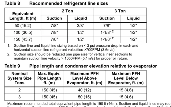
Table 8 Recommended refrigerant line sizes
Equivalent Length, ft (m)
2 Ton 3 Ton
Suction Liquid Suction Liquid
50 (15.2) 7/8" 3/8" 7/8" 1/2" 100 (30.5) 7/8" 1/2" 1-1/8"2 1/2"
150 (45.7) 7/8" 1/2" 1-1/8"2 1/2"
1. Suction line and liquid line sizing based on < 3 psi pressure drop in each and horizontal suction line refrigerant velocities >700FPM (3.6m/s).
2. Suction size should be reduced one pipe size for vertical riser sections to maintain suction line velocity > 1000FPM (5.1m/s) for proper oil return.
Table 9 Pipe length and condenser elevation relative to evaporator
Nominal System Size Tons Max. Equiv. Pipe Length ft. (m) Maximum PFH Level Above Evaporator, ft. (m) Maximum PFH Level Below Evaporator, ft. (m) 2 150 (45) 40 (12) 15 (4.6) 3 150 (45) 50 (15) 15 (4.6)
Maximum recommended total equivalent pipe length is 150 ft (46m). Suction and liquid lines may require additional specialty items when vertical lines exceed 20 ft. (6m) and/or condensing unit installation is more than 15 ft. (4.6m) below the evaporator. Contact Emerson Application Engineering for assistance.
Table 10 Line charges - refrigerant per 100 ft. (30m) of Type L copper tube
Line Size, O.D., in.
R-407C, lb/100 ft. (kg/30m) Liquid Line Suction Line
3/8 3.7 (1.7) — 1/2 6.9 (3.1) — 5/8 11.0 (5.0 0.4 (0.2) 3/4 15.7 (7.1) 0.6 (0.3) 7/8 23.0 (10.4) 1.0 (0.4) 1-1/8 — 1.7 (0.7) 1-3/8 — 2.7 (1.1)
Table 11 Refrigerant charge in Liebert pre-charged R-407C line sets
Line Size, in. Length, ft. (m) Charge R-407C, oz (kg)
3/8 liquid 15 (4.5) 5 (0.14)
30 (9) 10 (0.28)
5/8 or 7/8 suction 15 (4.5) 5 (0.14)
30 (9) 10 (0.28)
Table 12 Equivalent lengths for various pipe fittings, ft (m)
Copper Pipe
OD, in. Elbow Copper90 Degree Elbow Cast90 Degree 45 DegreeElbow Tee ValveGate GlobeValve AngleValve 1/2 0.8 (0.24) 1.3 (0.39) 0.4 (0.12) 2.5 (0.76) 0.26 (0.07) 7.0 (2.13) 4.0 (1.21) 5/8 0.9 (0.27) 1.4 (0.42) 0.5 (0.15) 2.5 (0.76) 0.28 (0.08) 9.5 (2.89) 5.0 (1.52) 3/4 1.0 (0.3) 1.5 (0.45) 0.6 (0.18) 2.5 (0.76) 0.3 (0.09) 12.0 (3.65) 6.5 (1.98)
Refrigerant Charge Requirements
Total R-407C refrigerant charge will be required only if units are evacuated during installation or maintenance. For safe and effective operation, refer to pressures in 5.5.3 - Piping Connections and Coolant Requirements.
Total Refrigerant = Units and Lines
Quick Connect Fittings
Be especially careful when connecting the quick connect fittings. Read through the following steps before making the connections.
1. Remove protector caps and plugs.
2. Carefully wipe coupling seats and threaded surfaces with a clean cloth. 3. Lubricate the male diaphragm and synthetic rubber seal with refrigerant oil.
4. Thread the coupling halves together by hand to insure that the threads mate properly.
5. Tighten the coupling body hex nut and union nut with the proper size wrench until the coupling bodies “bottom out” or until a definite resistance is felt.
6. Using a marker or pen, make a line lengthwise from the coupling union nut to the bulkhead. 7. Tighten the nuts an additional quarter-turn; the misalignment of the lines shows how much the
coupling has been tightened. This final quarter-turn is necessary to insure that the joint will not leak. Refer to Table 14 for torque requirements.
Table 13 Refrigerant charge
Model # Charge R-407C oz (kg) 60Hz 50Hz MM*24E/K — 7 (0.198) MM*36E/K MM*35E/K 7 (0.198) MC*24AL_H7 — 134 (3.80) MC*36AL_H7 MC*35AL_H7 213 (6.04) MC*26W_H7 — 41 (1.16) MC*38W_H7 MC*37W_H7 54 (1.54) PFH027-_L7 — 134 (3.80) PFH027-_H7 — 213 (6.04) PFHZ27-_L7 — 213 (6.04) PFH037-_L7 PFH036-_L7 213 (6.04) PFH037-_H7 PFH036-_H7 426 (12.08) PFHZ37-_L7 PFHZ36-_L7 426 (12.08) NOTE
When hard piping is used, complete all piping and evacuate lines before connecting quick connects.
Table 14 Connection sizes and torque
Size OD Cu Model Tons Coupling Size Torque Ib-ft.
3/8 2 and 3 #6 10-12
Site Preparation and Installation
Figure 13 Dimensions, evaporator and chilled water units with direct drive blower
Table 15 Net weights—evaporator and chilled water units
Model # Weight, lb (kg) 60Hz 50Hz MM*24E — 225 (102) 1" (25.4mm) 11" (279mm) 20" (508mm) 15" (381mm) 18" (457mm) 18" (457mm) 19-7/8" (505mm) Duct Flange 3/4" (19mm) 1" (25.4mm)
Filter Box (optional)
24" (610mm) Cabinet Dimension 18" (457mm) 18" (457mm) 18" (457mm) Cabinet Dimension same as above Hanging Bracket Shaded area indicates a recommended clearance of 30" (762mm) for access and filter removal
Shaded area indicates a recommended clearance of 30" (762mm) for access
and filter removal 7/8" (22mm) holes
for module rigging (typ. 2 each end).
Note: Unit is spaced evenly in reference to threaded rod centers 1-7/16" (37mm) 1-7/16" (37mm) 14" (356mm) Removable Access Panels 27-13/16" (706mm) Threaded Rod Centers Cabinet Outline Removable panel on side of plenum. Minimum clearance 30" (762mm) for filter
access and removal
Air Discharge out sides of plenum
Air Discharge out sides of plenum Cover Plate
Supplied With Plenum
Air Inlet through grille in center of plenum
24" (610mm)
Overall Dimension
Optional Air Distribution Plenum
All piping and electrical field connections are the same30" (762mm) Cabinet Dimension DPN000193 Rev. 3 6" (152mm) 48" (1219mm) Overall Dimension 3-7/8" (98mm) 14" (356mm) 14" (356mm) Customer-Supplied
Threaded Rods for Module Suport from Ceiling (Typ. 4) 11-1/8" (283mm) 5" (127mm) 3-1/4" (83mm) Overall Dimension Dimension 55-13/16" (1418mm) Rod Centers 57-13/16" (1468mm) 54" (1372mm)
Optional discharge air duct flange supplied when optional filter box is ordered 10-7/8" (276mm) 11-5/8" (295mm) Cabinet Threaded
Module Dimensions
Figure 14 Dimensions, evaporator units with optional belt drive blower assembly
Table 16 Net weight, high static blower module
Unit Net Weightlb (kg) High Static Blower Module 85 (39) Source: DPN000194, Rev. 3
DPN000194
Rev. 3
19" (483mm) Blower Box Dimension 4-29/32" (125mm) Cabinet to Cabinet 4-29/32" (125mm) Threaded Rod To Threaded Rod 57-13/16" (1468mm) Overall Dimension 55-13/16" (1418mm) Threaded Rod Centers54" (1372mm) Cabinet Dimension
High Static
Blower
Module
Evap
Unit
30" (762mm) Blower Box Dimension 5-7/8" (149mm) 29-7/8" (759mm) Threaded Rod Centers 3-7/32" (82mm) Base to Base 14" (356mm) Outlet Dimension 6-7/8" (175mm) 6-5/16" (160mm) Outlet 9-3/4" Outlet (248mm) 16-13/16" (427mm) Threaded Rod Centers24" (610mm) Cabinet Dimension 30" (762mm) Cabinet Dimension 18 " (457mm) Outlet Dimension