Abstract—In fuzzy control systems, fuzzification and defuzzification are two important procedures. Defuzzification plays an important part in the implementation of a fuzzy system, since the fuzzy data is not suitable for real time applications; it needs to be converted into crisp data. This paper proposes a novel VLSI architecture of a weighted average method (WAM) defuzzification method. The WAM of defuzzification is simple and is being generally used in comparison to more complex centre of gravity defuzzification method. The proposed architecture is modeled in very high speed hardware description language (VHDL) and implemented in Vertex-4 field programmable gate array (FPGA). The functional analysis has revealed that the proposed architecture is implementing WAM
Index Terms— Defuzzification; Fuzzy processor; Weighted Average Method; Low power; VLSI design
I. INTRODUCTION
HEconcept of fuzzy logic is generally being attributed to Lotfi Zadeh [1], who in his work has introduced mathematics of fuzzy sets nearly three decades ago. Fuzzy logic has applications in all domains of modern life and provides simplistic solution to complex problems [2-3]
Fuzzification, defuzzification and inference are three important segments of a fuzzy system. However, the fuzzy results generated cannot be used as such to the real time applications, hence it is necessary to convert the fuzzy quantities to crisp for further processing. This can be achieved by using defuzzification process. The defuzzification has the capability to reduce a fuzzy quantity to a crisp single-valued quantity. Defuzzification can also be called as "rounding off" method. Defuzzification reduces the collection of membership function values in to a single sealer quantity [4-7]. The various fuzzy systems are realized by different researcher for different applications. The original digital realization of fuzzy inference processor was performed by Toga and Watanabe [9-10]. H. Peyravi et al. [11] have proposed reconfigurable inference engine for the
Manuscript received November 22, 2013; revised December 20, 2013. The authors would like to acknowledge the support from NPST Saudi Arabia (11-NAN-2018-02). Dr. Sajad A Loan is associated with Jamia Millia Islamia (Central University) New Delhi, where he works as a Sr. Assistant Professor. (Corresponding author: [email protected]). Dr. Asim. M. Murshid and Dr.Ahmed Chalak Shakir are associated with the Computer Science Department, College of Science, Kirkuk University Iraq. Prof. Shuja A. Abbasi and Prof. Abdul Rahman Alamoud are associated with the Electrical Engineering Department, King Saud University.
analog fuzzy logic controller, based on Mamdani inference technique. J.M. Jou et al. [12], R. d 'Amore [13] and N. E. Evmorfopoulong et al. [14] have proposed different architecture for the fuzzy inference processor. A significant improvement is reducing power and reducing redundancy has been obtained in these structures. The inference engine performance is an important issue which needs to be addressed.. Many researchers have done a work on the defuzzification fuzzy processors. Roberto d’Amore et al [11] has developed a two input one output bit scalable architecture for fuzzy processors.
In this work, we propose a novel VLSI architecture of a defuzzifier. The defuzzifier is based on weighted average method, the simplest and generally used. The proposed architecture is modelled in very high speed hardware description language (VHDL) and implemented in Vertex-4 field programmable gate array (FPGA). In this work, two models have been designed to test the functionality of the proposed fuzzy processor. The defuzzified value has been obtained manually using the WAM technique initially, then the proposed architecture has computed the defuzzified values. It has been observed that a complete match exists between the manually calculated and the values generated by the proposed architecture. This shows that the proposed architecture is well designed and is realizing the WAM defuzzification method efficiently and accurately.
II. DEFUZZIFICATIONPROCESS
The fuzzy data obtained from the fuzzification process is not suitable for the real time applications and have to be converted into crisp form. The conversion of data from fuzzy form to crisp form is known as the defuzzification. It reduces the collection of membership function values into a single quantity. The different defuzzification methods used in literature are [1-5].
1. Max-membership principle. 2. Centroid method.
3. Weighted average method. 4. Mean-max membership. 5. Centre of sums.
6. Center of largest area.
7. First of maxima or last of maxima.
These methods have their own applications, advantages and disadvantages [1-5]. The researchers have developed various architectures of defuzzifiers depending on what application the fuzzy processor or the fuzzy controller is being designed for. Figure 1 shows the block diagram of a defuzzifier circuit. C1X1, C1X2, C2X1 and c2x2 are the fuzzy inputs to
A Novel VLSI Architecture of a Weighted
Average Method based Defuzzifier Unit
Sajad A. Loan, Member IAENG , Asim M. Murshid, Ahmed C. Shakir, Abdul Rahman Alamoud and Shuja A. Abbasi
the defuzzifier, which comprises of elements and their associated membership functions. The defuzzifier block is having an architecture intact based the defuzzification techniques as mentioned above to extract the defuzzified or the crisp value. The crisp output value only can be used to control various processes or mechanisms.
Figure 1: Block diagram of a defuzzifier.
The defuzzification technique used in this work is the weighted average method. This method is using for symmetrical membership only, also is the most accurate method among all. The researchers have generally designing the VLSI architecture of the WAM defuzzifier; however, in this work an efficient WAM based defuzzifier is designed and implemented. Equation 1 shows the model for the WAM based defuzzification [1-5].
WAM = ∑ ∑ (1)
In this work, we have used a model to study and realize the defuzzification architecture as shown in Figure 2. In this model two rules are being fired and Mamdani implication has been used for inference. We have used aggression of rules, as the overall consequent is being obtained from the two individual consequent in each set. In each set, the minimum of two antecedent membership values is propagated to the consequent as “AND” connective is used between the two antecedents in the rule. The propagated membership value from operations on the antecedents truncates the membership function for the consequent for that rule. The truncated membership functions from each rule are aggregated according to the following equation used for conjunctive system of rules [3].
μy(y) = min (μy1 (y), μy2 (y), ..., μyr (y)) for y ϵY (2) Each rule comprises of two antecedents (A1, B1 and A2, B2) and one consequent (C1, C2) and is represented as
IF(X is A1) AND (Y is B1) then (Z isC1) (3)
IF(X is A2) AND (Y is B2) then (Z isC2) (4)
In MODEL 1, as shown in Figure 2, FA1 and FB1 are the first and second fuzzy antecedents of the first rule, respectively, and C1 refers to the fuzzy consequent of that fuzzy rule. Since the antecedents are connected by logical "AND", therefore, the minimum membership value of the antecedents propagate through to the consequent. This process truncates the membership function for the consequent of each rule. Similarly, FA2 and FB2 are the first and second fuzzy antecedents of the second rule, respectively, and C2 refers to the fuzzy consequent of the second fuzzy rule. This process is the inference and it
follows Mamdani’s implication method, which is the most common in practice and in the literature. The union of two consequents C1 and C2 is shown in row 3 of Figure 2. From this union the defuzzified value is being obtained by using the weighted average method (WAM) technique, as given in equation (1).
MODEL 1
(a) Generator C1
(b) Generator C2
[image:2.595.306.561.136.453.2](c) Union of C1 & C2
Figure 2: Fuzzification, Inference and Defuzzification using weighted average method for MODEL 1.
III. CALCULATIONOFDEFUZZIFIEDVALUES The defuzzified or crisp value for MODEL 1 can be calculated first manually and then using the proposed architecture. It is important that the two values must match; otherwise the proposed architecture is not well designed. In this study, weighted average method (WAM) is being used to calculate the defuzzified value. Figure 3 again shows the defuzzification for the MODEL 1 as given by Figure 2. The application of equation (1) to Figure 3 will generate the defuzzified value of model 1. The defuzzified value obtained out of WAM defuzzifier (YWAM) is again given by equation (1’)
[image:2.595.316.541.659.766.2]YWAM = ∑ ∑ (1’) It can be again written as
YWAM = / (2) where
N = ∑ (z).z (3)
D = ∑ (z) (4) N and D can be again written as
N = CC1 ∗ T1 CC2 ∗ T2
D = T1 T2
Where CC1 and CC2 is the center of the first and second trapezoid MFs respectively, T1 and T2 are the maximum values of the first and second trapezoid MFs respectively, as shown in Figure 3
Y
WAM ∗ ∗(5)
The points CC1 and CC2 are given by
CC1
1 1
CC1
8
0
2
0
4
CC2 C2X2 C2X1
2 2 1
CC2
6
10
The following hexadecimal equivalent of T1 and T2 has been used.
T1 = 0.5 = A H, T2 = 0.25 = 5 H. The values of N and D are computed below N = CC1 ∗ T1 CC2 ∗ T2 = 4*10 + 10*5 = 90 D = T1 T2 10 5 15
Y
WAM6
H
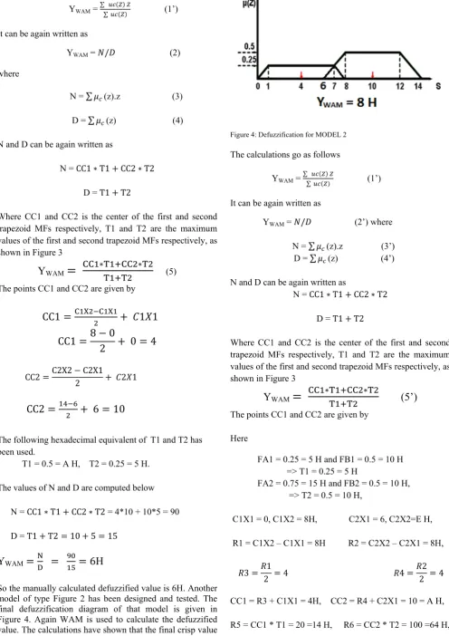
[image:3.595.50.547.59.762.2]So the manually calculated defuzzified value is 6H. Another model of type Figure 2 has been designed and tested. The final defuzzification diagram of that model is given in Figure 4. Again WAM is used to calculate the defuzzified value. The calculations have shown that the final crisp value as 8H.
Figure 4: Defuzzification for MODEL 2
The calculations go as follows
YWAM = ∑ ∑ (1’) It can be again written as
YWAM = / (2’) where N = ∑ (z).z (3’) D = ∑ (z) (4’) N and D can be again written as
N = CC1 ∗ T1 CC2 ∗ T2
D = T1 T2
Where CC1 and CC2 is the center of the first and second trapezoid MFs respectively, T1 and T2 are the maximum values of the first and second trapezoid MFs respectively, as shown in Figure 3
Y
WAM ∗ ∗(5’)
The points CC1 and CC2 are given by Here
FA1 = 0.25 = 5 H and FB1 = 0.5 = 10 H => T1 = 0.25 = 5 H
FA2 = 0.75 = 15 H and FB2 = 0.5 = 10 H, => T2 = 0.5 = 10 H,
C1X1 = 0, C1X2 = 8H, C2X1 = 6, C2X2=E H, R1 = C1X2 – C1X1 = 8H R2 = C2X2 – C2X1 = 8H,
3 1
2 4 4 2
2 4
CC1 = R3 + C1X1 = 4H, CC2 = R4 + C2X1 = 10 = A H,
[image:3.595.74.228.398.526.2]O M D
120 15 8 H
The same procedure has been used for other defuzzified model, not shown in a figure. The defuzzified value obtained is 7.
IV. HARDWARE REALIZATION OF THE DEFUZZIFICATION PROCESS
[image:4.595.309.557.56.225.2]In section III, the defuzzified values have been manually calculated using the weighted average method, as shown in Figure 3 and Figure 4. However, manual calculation is not sufficient, a real hardware is needed which will automatically calculate the defuzzified values. Therefore, in this section, a novel architecture of a defuzzifier based on W. A. M. technique has been designed and simulated. The proposed architecture has been modeled in VHDL and has been implemented in field programmable gate array (FPGA). The defuzzified output in the W.A.M. method is given by the following equation
[image:4.595.51.293.316.515.2]WAM = ∑ ∑ (1)
Figure 5: Architecture for numerator of WAM defuzzifier.
Since equation (1) carries summation in both the numerator and denominator, so two architectures have been developed for numerator and denominator separately and have been combined together. The output of the weighted average method defuzzifier is given below as
Y
WAM∗ ∗
Where
CC1 C1X2 C1X1
2 1 1
and
CC2 C2X2 C2X1
2 2 1
T1 = MIN (FA1, FB1) T2 = MIN (FA2, FB2)
Figure 6: Architecture for numerator of WAM defuzzifier.
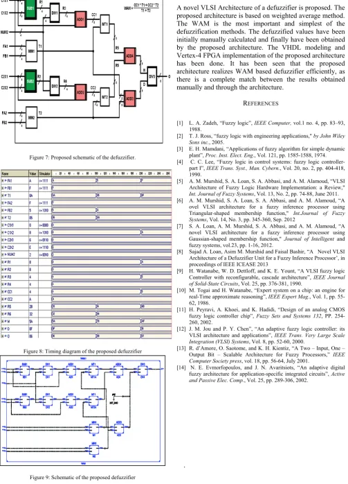
Figure 5 and Figure 6 are the architecture realization of the numerators and denominators of equation (5’). The two architectures are merged into a single architecture as shown in Figure 7. The VHDL modeling of the proposed architectures have been performed. The functional analysis is shown in Figure 8. It is clear from the functional analysis that there is a clear cut match between the results obtained manually and results generated by the architecture. In the first T-state of the functional analysis, the output of the defuzzifier ‘O’ is 6H, which is same as obtained manually for Figure 3. Similarly, for T-State second and third, the outputs of the defuzzifier is 8H and 7H respectively, which is same as calculated manually. This shows the proposed architecture is realizing the defuzzifier action efficiently and accurately.
V. FPGA IMPLEMENTATION OF THE DEFUZZIFIER
[image:4.595.53.232.627.754.2]A Vertix-4 XC4VLX160 FPGA platform from XILINX has been used to implement the proposed architecture. The FPGA has around 135168 4-input look up tables (LUT) and 768 bonded input/output buffers (IOB). The FPGA logic resource used in an implementation are shown in Table 1, schematic and netlist generated of the proposed defuzzifier shown in Figure 9 and 10 respectively. The implementation results shown in Table 1 show that that there is further scope for improvement in the proposed structures by incorporeity more parallelism in the architecture.
TABLE 1: FPGA Implementation results
Device Utilization Summary (FPGA: XC4VLX160-FF1148)
Logic Utilization Used Available Utilization
Number of 4 input LUTs 335 135,168 1% Number of occupied Slices 173 67,584 1% Number of Slices containing
only related logic 173 173 100%
Number of Slices containing
unrelated logic 0 173 0%
Total Number of 4 input LUTs 335 135,168 1% Number of bonded IOBs 44 768 5% Number of DSP48s 2 96 2% Average Fanout of Non‐Clock
Figure 7: Proposed schematic of the defuzzifier.
[image:5.595.49.553.93.792.2]Figure 8: Timing diagram of the proposed defuzzifier
Figure 9: Schematic of the proposed defuzzifier
VI. CONCLUSION
A novel VLSI Architecture of a defuzzifier is proposed. The proposed architecture is based on weighted average method. The WAM is the most important and simplest of the defuzzification methods. The defuzzified values have been initially manually calculated and finally have been obtained by the proposed architecture. The VHDL modeling and Vertex-4 FPGA implementation of the proposed architecture has been done. It has been seen that the proposed architecture realizes WAM based defuzzifier efficiently, as there is a complete match between the results obtained manually and through the architecture.
REFERENCES
[1] L. A. Zadeh, “Fuzzy logic”, IEEE Computer, vol.1 no. 4, pp. 83–93, 1988.
[2] T. J. Ross, “fuzzy logic with engineering applications," by John Wiley Sons inc., 2005.
[3] E. H. Mamdani, “Applications of fuzzy algorithm for simple dynamic plant”, Proc. Inst. Elect. Eng., Vol. 121, pp. 1585-1588, 1974. [4] C. C. Lee, “Fuzzy logic in control systems: fuzzy logic
controller-part I”, IEEE Trans. Syst., Man. Cybern., Vol. 20, no. 2, pp. 404-418, 1990.
[5] A. M. Murshid, S. A. Loan, S. A. Abbasi, and A. M. Alamoud, “VLSI Architecture of Fuzzy Logic Hardware Implementation: a Review," Int. Journal of Fuzzy Systems, Vol. 13, No. 2, pp. 74-88, June 2011. [6] A. M. Murshid, S. A. Loan, S. A. Abbasi, and A. M. Alamoud, “A
ovel VLSI architecture for a fuzzy inference processor using Triangular-shaped membership function," Int.Journal of Fuzzy Systems, Vol. 14, No. 3, pp. 345-360, Sep. 2012
[7] S. A. Loan, A. M. Murshid, S. A. Abbasi, and A. M. Alamoud, “A novel VLSI architecture for a fuzzy inference processor using Gaussian-shaped membership function," Journal of Intelligent and fuzzy systems, vol.23, pp. 1-16, 2012.
[8] Sajad A. Loan, Asim M. Murshid and Faisal Bashir, “A Novel VLSI Architecture of a Defuzzifier Unit for a Fuzzy Inference Processor’, in proceedings of IEEE ICEASE 2013
[9] H. Watanabe, W. D. Dettloff, and K. E. Yount, “A VLSI fuzzy logic Controller with reconfigurable, cascade architecture”, IEEE Journal of Solid-State Circuits, Vol. 25, pp. 376-381, 1990.
[10] M. Togai and H. Watanabe, “Expert system on a chip: an engine for real-Time approximate reasoning”, IEEE Expert Mag., Vol. 1, pp. 55- 62, 1986.
[11] H. Peyravi, A. Khoei, and K. Hadidi, “Design of an analog CMOS fuzzy logic controller chip”, Fuzzy Sets and Systems 132, PP. 254- 260, 2002.
[12] J. M. Jou and P. Y. Chen”, “An adaptive fuzzy logic controller: its VLSI architecture and applications”, IEEE Trans. Very Large Scale Integration (VLSI) Systems, Vol. 8, pp. 52-60, 2000.
[13] R. d’Amore, O. Saotome, and K. H. Kientiz, “A Two – Input, One – Output Bit – Scalable Architecture for Fuzzy Processors,” IEEE Computer Society press, vol. 18, pp. 56-64, July 2001.
[14] N. E. Evmorfopoulos, and J. N. Avaritsiots, “An adaptive digital fuzzy architecture for application-specific integrated circuits”, Active and Passive Elec. Comp., Vol. 25, pp. 289-306, 2002.