University of Southampton Research Repository
ePrints Soton
Copyright © and Moral Rights for this thesis are retained by the author and/or other copyright owners. A copy can be downloaded for personal non-commercial
research or study, without prior permission or charge. This thesis cannot be
reproduced or quoted extensively from without first obtaining permission in writing from the copyright holder/s. The content must not be changed in any way or sold commercially in any format or medium without the formal permission of the
copyright holders.
When referring to this work, full bibliographic details including the author, title, awarding institution and date of the thesis must be given e.g.
UNIVERSITY OF SOUTHAMPTON
Partial Singular Integro-Differential Equations Models for Dryout in
Boilers
Mphaka Joane Sankoela Mphaka
Doctor of Philosophy
Faculty of Mathematical Studies
UNIVERSITY OF SOUTHAMPTON ABSTRACT
FACULTY OF MATHEMATICAL STUDIES MATHEMATICS
Doctor of Philosophy
PARTIAL SINGULAR INTEGRO-DIFFERENTIAL EQUATIONS MODELS FOR DRYOUT IN BOILERS
by Mphaka Joane Sankoela Mphaka
A two-dimensional model for the annular two-phase flow of water and steam, along with the dryout, in steam generating pipes of a liquid metal fast breeder reactor is proposed. The model is based on thin-layer lubrication theory and thin aerofoil theory. The exchange of mass between the vapour core and the liquid film due to evaporation of the liquid film is accounted for in the model. The mass exchange rate depends on the details of the flow conditions and it is calculated using some simple thermodynamic models. The change of phase at the free surface between the liquid layer and the vapour core is modelled by proposing a suitable Stefan problem. Appropriate boundary conditions for the model, at the onset of the annular flow region and at the dryout point, are stated and discussed. The resulting unsteady nonlinear singular integro-differential equation for the liquid film free surface is solved asymptotically and numerically (using some regularisation techniques) in the steady state case, for a number of industrially relevant cases. Predictions for the length to the dryout point from the entry of the annular regime are made. The influence of the constant parameter values in the model (e.g. the traction r provided by the fast flowing vapour core on the liquid layer and the mass transfer parameter 77) on the length to the dryout point is investigated.
Contents
1 General Introduction 1
1.1 The Physical Problem 2 1.1.1 Flow Patterns 3 1.1.2 The Annular Region and the Dryout Point 5 1.1.3 Some Models which are Related to the Presented Problem 6 1.1.4 An Overview of Work Performed in this Thesis 8
2 The Full Unsteady Model 9
2.7 The Full Model 28 2.7.1 Heat Transfer Coefficient Constitutive Laws 30 2.7.2 Constant Wall Temperature Problem 30 2.7.3 A Varying Wall Temperature Problem 31 2.7.4 Constant Wall Heat Flux Problem 31 2.7.5 Initial and Boundary Conditions of the Full Model 32 2.8 Problem in the Liquid Metal 32
3 Steady States for the Constant Wall Temperature Problem 36
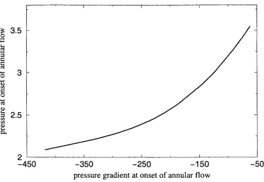
3.1 Limiting Cases and Paradigm Problems 36 3.1.1 Boundary Conditions 37 3.1.2 Analysis of the Integral Equation 38 3.1.3 An Inversion Technique Using Properties of Abel's Equation 40 3.1.4 Numerical Solution 42 3.1.4.1 A Conventional Method 42 3.1.4.2 A Different Approach 45 3.1.5 A Nonlinear Problem 48 3.1.5.1 Asymptotics and Regularisation 49 3.1.5.2 Numerical Scheme and Results 50 3.2 The Full Nonlinear Problem 55 3.2.1 Analytical Treatment 55 3.2.2 Asymptotic Analysis 58 3.2.3 Regularisation and Pressure Gradient Condition 61 3.2.4 Numerical Scheme 64 3.2.5 Numerical Results and Discussions 67 3.2.5.1 Pressure and Pressure Gradient Effects 74
4 Steady State Solutions: A Non-constant Wall Temperature Problem 82
4.3.1 Numerical Results 96 4.4 Nonregularised Problem and the Pressure Condition 96 4.4.1 Analytical Manipulations 97 4.4.2 Numerical Treatment 102 4.4.3 Some Preliminary Numerical Results and Discussions 105
5 Unsteady Flows 112
5.1 Literature Review 112 5.2 Similarity Solutions 114 5.3 Linear Stability Analysis 116 5.3.1 A Constant Pressure Gradient Problem 117 5.3.1.1 A Non-Zero Pressure Gradient Problem 118 5.3.1.2 A Zero Pressure Gradient Problem 121 5.3.2 The Full Problem 127 5.3.2.1 A Numerical Method 130 5.3.2.2 Analytical Manipulations 130 5.3.2.3 Discretisation 132 5.3.2.4 Numerical Results 137 5.3.2.5 Analytical Results: Gas Core Pressure and Surface Tension
Effects 143
6 Conclusions 146 6.1 Avenues for Further Research 149
Acknowledgements
I would like to first of all acknowledge my supervisor Prof. Alistair Fitt for his advice, encouragement and time especially for those first three months of my research. I would also like to thank all other members of the Industrial Applied Mathematics group with whom I have had useful discussions in one way or the other. These include my advisor Prof. Colin Please, Dr. Giampaolo D'Alessandro and Dr. Jeff Dewynne (now at Oxford) for over-lending me his books for almost two years! I wish to extend my appreciation to all the members of the faculty office, in particular Mrs Yvonne Oliver, for their help from time to time with the administrative stuff.
I am very grateful to the Association of Commonwealth Universities in UK (and all those who handle all the administrative stuff, including Mrs. Sefika at LNMD!) for supporting me financially throughout this study. I cannot resist to mention that an opportunity to study (or live), for a considerable length of time, away from own country (for everybody) goes way beyond the academics; it provides a chance to celebrate (instead of being cynical or dubious about) people's differences in temperament, culture and all sorts of other things really.
I also wish to thank wholeheartedly all those who helped me and encouraged me throughout all the levels of my education; those who saw in me then what I could not possibly see in myself! These include all those at Thaba-Phats'oa Primary, Zenon High, Lesotho High and MACS, NUL! I would definitely not forget all the friends I have made throughout these times and whom, for some reason, we have kept in touch in one way or another; I wish you all the beauties and challenges of the uncertain but certainly bright future!
My greatest appreciations to Dr. Robert Craine (Bob!), Margery and their wonderful family for an unmeasurable support throughout my time here in Southampton - it is indeed those little positive debts that one cannot pay!
I have met and known an "uncountable" number of friends from all over the world here in Southampton. These include Martin Pope, Vladislav Putyatin, Michael Sharpe, Gabriela Gonzalez Castro, Eva Vincente Alonso, Sharon Kirkham, Marcus Tindall, ... - the list is truly inexhaustible but you know who you are guys - and all the very best to you all!
Chapter 1
General Introduction
The study of multiphase flow dynamics is frequently undertaken in the areas of natural sciences and engineering. A multiphase flow is simply described by Wallis (1969) [90] as the simultaneous flow of several phases, where a phase is a state of matter, e.g. solid, liquid or gas. There are numerous publications on this subject which cover fields such as blood flow, dust storms, air pollution, fluidised beds, sedimentation and pneumatic conveyors. These publications include those of Soo (1967) [76], Wallis (1969) [90], Bergles & Ishigai (1981) [11], Azbel (1981) [6], Chisholm (1983) [18] and Whalley (1987) [92] to name but a few. Owing to the vast and broad scope of the subject of multiphase flows, we do not attempt to describe the study of all aspects of the subject here since this would distract the reader from the main theme of this thesis. This thesis is devoted to mathematical modelling and analysis of an "annular" two-phase flow of an evaporating thin viscous liquid film of water (adhering to a heated wall) and its fast flowing "vapour/gas core" (the technical terminology will become clearer as we describe the physical problem in section (1.1)).
investigations of the closing and opening of holes in thin liquid films by Moriarty & Schwartz (1993) [53]; the study of drying paint layers by Howison et al (1997) [40]; the investigations on the spreading of thin liquid drops on planar substrates when subjected to a jet of air blowing normally to the substrate by McKinley et al (1999) [52]; the study of thin film curtain flows on rotating cylinders by Duffy 8z Wilson (1999) [27]; and the investigations into the blade coating phenomena by Ross et al (1999) [68]. A significant amount of the recent research involving the flow of non-isothermal thin liquid films (including the current problem of interest), on the other hand, has been largely motivated by the flows which are commonly observed in aerospace, power and process engineering industries. Examples include the study of ice and water film growth from incoming supercooled droplets by Myers & Hammond (1998) [55]; the study of the cooling of turbine blade tips, rocket engines, hot fuel element surfaces in hypothetical nuclear reactor accidents (see for example, a review by Bankoff (1994) [9]); and investigations on the growth of a vapour bubble in nucleate boiling by Wilson et al (1999) [95].
In the problem studied here (whose motivation is explained in section (1.1)), a mathemat-ical model for the two-phase annular flow of water and vapour in steam generating pipes of a Liquid Metal Fast Breeder Reactor (LMFBR) is proposed and analysed. The main aim of the model is to allow predictions to be made for the position of "dryout point". The model is based on thin aerofoil theory and thin-layer lubrication theory and it takes into account the mass exchange between the liquid film and the gas core due to evaporation from the liquid film. The resulting governing equation is a partial nonlinear singular integro-differential equa-tion for the liquid film free surface. It contains Hilbert transforms which are characterised by a Cauchy kernel of the form (£ — a:)"1. The solutions of the equation are achieved by em-ploying both appropriate asymptotic and numerical techniques. The linear stability of some solutions is investigated as well. Therefore, this thesis concerns mathematical modelling, asymptotic techniques and numerical methods.
1.1 The Physical Problem
Heat is then transferred from the coolant to water in the boiling component where steam is produced to drive turbines in order to create electricity. There are different kinds of nuclear reactors depending on many factors one of which is the type of coolant that is used. Some examples of these are explained in detail by Etherington (1958) [28]. In the Liquid Metal Fast Breeder Reactor, for example, a liquid metal is used as the coolant, a common choice being sodium since it has a high boiling point at atmospheric pressure and therefore the nuclear reactor may operate virtually unpressurised. Thus, in the event of Loss of Coolant Accident (LOCA) in which there is a break in the boundary of the nuclear system (Prosperetti & Plesset, 1984) [67], the damage and spread of contaminated material is minimised.
1.1.1 Flow Patterns
Flow of liquid metal I
v
Dry out point ,«=_
Gas core «^_
Thin liquid
Flow of gas/vapour
-*• Single-phase vapour -*• Dispersed-drop flow
-*- Annular flow
•*- Churn flow -*" Plug flow •*" Bubbly flow •** Single-phase liquid
Inlet of water
In the annular region, a flow of continuous liquid film along the pipe wall surrounds a core of fast flowing gas. Typically, the gas contains some liquid droplets which are believed to be a result of break up of waves which are usually present at the liquid film free surface, and undercuttings of the liquid film free surface by the increasing velocities in the gas core. In this region, the liquid film is superheated. Thus, formation of the vapour bubbles at the pipe wall has significantly decreased to a point that it is negligible and the gas production is due to evaporation of the thin liquid film free surface. The liquid droplets in the gas core continue to exist and slowly evaporate beyond the annular flow region into a dispersed-drop flow region, where all the liquid film along the pipe has evaporated as well. The liquid droplets in the gas core continue to evaporate until only a single-phase vapour region is present. It should be mentioned that there are many other intermediate flow regimes, e.g. wispy-annular flow, but the ones described above represent the minimum which can sensibly be defined (Whalley, 1987) [92]. The description of the intermediate regimes is qualitative and subjective (Azabel, 1981) [6] and therefore different sources of literature may describe them differently. Wispy-annular flow, for example, is differentiated from the Wispy-annular flow by a thicker liquid film (than one in the annular flow region) on the pipe wall and a higher concentration of liquid droplets (which are larger and nearly amalgamated) in the gas core. We will not try to describe these intermediate regimes in this study although the interested reader may consult the cited literature.
It should be mentioned that the flow regimes are also influenced by the orientation of the pipe at low water velocities at the inlet of the pipe. In horizontal pipes, for example, the gas bubbles tends to concentrate and travel on the upper side of the pipe. There is also a possibility that, at very low velocities, a stratified flow region may develop after the plug flow. In this case both the liquid and vapour phase flow separately with arguably a smooth interface. It is also usually the case that prior to the annular flow regime, a wavy flow region develops as a result of the interface being disturbed by the coherent travelling waves as the vapour velocities increase in the gas core. In the annular flow, the liquid film may not be continuous around the whole circumference of the tube but it is thicker at the base of the pipe. For high inlet water velocities, the influence of gravity is negligible and therefore the difference between the flow regimes in the vertical pipe and the horizontal one is virtually not existent.
1.1.2 The Annular Region and the Dryout Point
as functions of mixture quality and mass velocity. Moreover, at the operating conditions of the liquid metal nuclear reactor, (which are approximately pressures of 200 bar and hence a water saturation temperature of Ts = 365°C) the flow pattern maps of Bennett et al (1965)
[10] suggest that annular flow comprises at least 80 - 90% of the two-phase flow region. Furthermore, the annular flow regime in steam generating pipes has a fundamental feature of an exchange of mass between the liquid film and the gas core. This phenomenon consists of evaporation of the liquid film, typically at the free boundary; droplet entrainment (from the liquid film into the gas core) which is believed to be a result of the break up of large amplitude coherent waves which are usually present at the surface of the liquid film; and deposition of liquid drops from the gas core. The annular flow regime also contains the dryout point, where complete evaporation of the liquid film occurs.
At the dryout point, there is a sharp increase in the temperature of the pipe wall because the thermal conductivity of the gas phase, which is now in direct contact with the wall, is much less than that of the liquid phase. The determination of the position of the dryout point is not a trivial problem (see also Fisher &; Pearce, 1993) [29] since, for example, in the event that deposition of liquid drops occurs rapidly, the liquid film may reform hence rewetting and causing the temperature of the pipe wall to drop. If the processes of dryout and rewetting occur periodically, thermal stresses may be set up in the wall which could lead to cracking of the pipe. Therefore, a good understanding of the dryout phenomenon is essential to predict the lifetime of the steam generating pipes, as this process directly affects the integrity of the pipes. Moreover, the position of the dryout point affects the amount of evaporation which can occur in the pipes for a given value of the heat flux, and it is of great importance in the design of evaporators, steam boilers and nuclear reactors (Bankoff, 1994; Collier &: Thome, 1994) [9], [20].
1.1.3 Some Models which are Related to the Presented Problem
these systems. The general attitude adopted in the literature is that two-phase flows obey all the basic laws of fluid mechanics with equations more complicated and/or more numerous than those describing the single-phase flows. Thus the models are based on the conservation laws of mass, momentum and energy.
Practically all of the early literature indicates that the modelling of two-phase flows consid-ered the mixture mass, momentum and energy conservation laws (see for example, a review by Yadigaroglu & Lahey, 1976) [97]. This is a simple, but also not accurate, method of analysing two-phase flows. The properties of the mixture, e.g. velocity, temperature, den-sity and viscoden-sity, are calculated average properties of the two phases. The challenge in the mixture modelling is then of developing techniques to determine these weighted average prop-erties and rearranging the resulting equations until they resemble equivalent equations of a single-phase flow. There are numerous approaches in the literature adopted by researchers and we are not going to make a review of them here. However, it is worth mentioning that a frequently employed approach is to express the properties of each phase, in the conservation of mass, momentum and energy equations, in terms of a mixture quality. A mixture quality is defined as mass flux of one phase divided by total mass flux of the two phases. Later models, on the other hand, consider separately the conservation laws for each phase in order to improve accuracy of the mathematical representation. These equations can then be com-bined to describe the total flow. The equations are many with numerous unknowns. Thus, in general the problem is intractable. Therefore, it requires some simplifications and closure conditions which can only be supplied by prescribing appropriate interaction laws of mass, momentum and energy between the phases. This is non-trivial and researchers frequently resort to a great number of hypotheses.
of burnout or dryout heat transfer. The basic equations are that of the film flow rate, and the flow characteristics are described very schematically and empirically.
1.1.4 An Overview of Work Performed in this Thesis
We now summarise the work of this thesis. In chapter 2, an unsteady two-dimensional mathematical model for the two-phase flow of a thin liquid film (adjacent to a heated pipe wall) and its fast flowing gas core, along with the dryout point, is proposed. A number of assumptions, relevant to the current conditions of interest, are made and discussed in detail. The thin liquid film is modelled by employing thin-layer lubrication theory. The flow in the gas core is modelled as an incompressible, inviscid and irrotational flow. The liquid film adjacent to the wall is treated as a small perturbation to the gas flow. This allows the application of the thin aerofoil theory. A constitutive equation for the transfer of mass, by evaporation, from the liquid film into the gas core is proposed by specifying an appropriate Stefan problem.
Chapters 3 and 4 deal with numerical solutions of the steady state cases of the model when a constant wall temperature is specified and when a specific non-constant wall temperature is prescribed, respectively. Chapter 5 is mainly concerned with linear stability analysis (with respect to small temporal perturbations) of the steady state numerical solutions obtained for the constant wall temperature problem. The results are compared with those analysed for some simple paradigm problems. Finally, chapter 6 summarises some conclusions and discusses possible further work.
Chapter 2
The Full Unsteady Model
In this chapter, we systematically develop an unsteady mathematical model for the dry-out front position. The resulting model amounts to a nonlinear singular integro-differential equation for the unknown liquid film free surface. Plausible boundary conditions are stated. Before we proceed with the mathematical modelling, however it is instructive to review some previous relevant work.
2.1 Literature Review
2.1.1 Mathematical Modelling
Lat-timer Sz Fitt (1998) [47] investigate transient effects by assuming that the unsteadiness in the resulting problem is driven by a time dependent suction slot pressure. Pope (1999) [65] studies the problem of de-icing (removal of a thin ice layer) by the injection of heated fluid from a slot. Just like the other models mentioned earlier, this problem is also a development of the original model by Fitt et al (1985) [32]. A complementary problem of slot suction from an inviscid channel flow, when the suction and free stream total pressure heads are equal, is investigated by Dewynne et al (1989) [25]. Other authors use hodograph techniques (by using Christofel transformations, for example) to model fluid flows in some complicated physical geometries, and the resulting equations of motion are nonlinear singular integro-differential equations. Forbes & Schwartz (1982) [35] tackle a two-dimensional problem of steady flow of a fluid with a free surface over a semicircular obstacle on the bottom of a stream. A hodograph variable is specified and the problem is transformed from an otherwise difficult physical space into a simpler hodograph space. Similar techniques are employed to study other problems in various difficult geometries by a number of authors. These include King Sz Bloor (1987) [44] in their study of a steady free surface flow of an ideal fluid over a semi-infinite step; Asavanant & Vanden-Broeck (1994) [4] who investigate two-dimensional flows past a parabolic obstacle lying on the free surface in a fluid of infinite depth; and Tuck & Vanden-Broeck (1998) [87] who study "ploughing flows", i.e. flows over shallowly-submerged bodies which may be thought of as a model for an agricultural plough.
core flow and the change of phase at the unknown boundary of the liquid layer. Therefore, the associated boundary conditions also differ considerably.
2.1.2 Numerical Methods
It is worth mentioning at this point that, due to their frequent appearance in modelling physical phenomena, a vast amount of literature is available on the numerical solution of linear (or linearised) singular integral equations. The interested reader is referred to a wide range of numerical techniques presented by various authors in the literature, see for example, Tuck (1991) [86], Chakrabarti & Tsahoo (1996) [16], Cuminato (1996) [21], Kim (1998) [43], De Klerk et al (1995) [23], Prankel (1995) [37] and Fitt et al (1995) [30]. Other authors compute the singular behaviour of the linear Cauchy singular integral equations with both constant and variable coefficients (Srivastav, 1992; Li Sz Srivastav, 1997) [84], [49]. Although numerical methods for linear equations are interesting, they are not really applicable to our problem. Here, we will therefore focus briefly on some of the references which employ numerical techniques to solve nonlinear singular integro-differential equations and these are much rarer. An obvious reason for undertaking this part of literature review is to learn of what may be already available for application when we will be tackling the current problem numerically later in this thesis.
to remove any derivatives of the unknown function. After applying the relevant boundary conditions to evaluate the constants of integration and inversion, the problem is then solved numerically by employing a direct iterative relaxation scheme. The success of this numeri-cal technique is primarily made possible by the fact that the resulting equation contains no principal-value integrals. It is not clear, however, whether the fact that the behaviour of the unknown function at one (or more) end point contains a logarithmic singularity also plays an important role. King & Tuck (1993) [45], instead, employ regularisation techniques to deal with the singular behaviour of the derivative of the unknown function near an end point prior to any numerical manipulations. Their resulting equation is then discretised using fi-nite differences and a collocation method is employed to evaluate the Cauchy principal-value integral. The final challenge of King &; Tuck (1993) [45] is to solve a set of nonlinear alge-braic equations for the unknown function at discrete points, and this is done using a Powell's method as implemented in the NAG library routine C05NBF.
As a result of using a conformal mapping technique to map a region of complicated geom-etry, which is occupied by an irrotational inviscid fluid, to a region with a simpler geomgeom-etry, Bloor (1978) [12], Schwartz & Vanden-Broeck (1979) [73], Forbes & Schwartz (1982) [35] and King & Bloor (1987) [44] also solve various nonlinear singular integral equations using different, but closely related, computational techniques. In general, the methods are based upon finite difference approximations. The domain of the independent variable is subdivided into subintervals. The derivatives are approximated by appropriate finite difference formu-lae. Evaluation of the Cauchy principal-value integrals includes use of Taylor expansions of the integrand about a point, singularity removal by some elementary transformations and singularity subtraction leaving a singular integral plus a natural-logarithm term. Ordinary integrals are calculated using Simpson's rule. Finally, iterative methods are employed to solve the resulting set of nonlinear algebraic equations.
An analysis of Newton iteration numerical methods is carried out by Junghanns (1994) [42] for some classes of nonlinear singular integral equations. It might be useful to mention at this stage that Varley Sz Walker (1989) [89] obtain analytical solutions (not numerical) to certain classes of linear singular integro-differential equations over an infinite range. However, the closed-form solution of nonlinear singular integro-differential equations over a finite range still remains an open question.
2.2 A Model for Dryout Front Position
and the gas core. Suggested mechanisms by which this phenomenon occurs are entrainment of liquid drops from the liquid film to the gas core due to undercutting of crests on the film free surface, deposition of liquid drops from the gas core and evaporation in the liquid film. Typically, the liquid in the thin film is superheated (see for example Kirillov et al, 1985; Higuera, 1987; Prosperetti & Plesset, 1984) [46], [39], [67] and therefore evaporates at the interface between the liquid film and the gas core. This superheating is possibly due to suppression of a complex phenomenon of heterogeneous nucleation and ordinary boiling by, for example, either heating or depressurising the liquid very rapidly (Higuera, 1987) [39]. The rate of evaporation depends on the external heat flux supplied to the boiling pipes. At the operating conditions of interest the results of Collier (1972) [19] suggest that neither entrainment nor deposition occurs rapidly. Therefore, we assume the dryout phenomenon is mainly driven by evaporation of the liquid film. Deposition, as one might expect, seems to be directly proportional to the concentration of liquid droplets in the gas core (Whalley, 1977, 1987; Fisher & Pearce, 1993) [91], [92], [29] while on the other hand, the process of droplet entrainment appears to be a subtle matter. We adopt a simple approach in modelling this problem, since in any mathematical modelling of a problem it is always good practice to build a model from the simplest foundations (Alpabhai et al, 1997) [1]. It is rarely successful to try and combine all realistic features into a model from the start. It should be noted, however, that adjustments can be made in our models to account for these other factors. In this study we concentrate exclusively on the problem when the dryout phenomenon is driven by the evaporation process from the liquid film free surface.
2.3 Liquid Film Flow
We proceed by first considering the thin liquid layer adjacent to the heated pipe wall. The flow in the gas core will be considered later. In order to suggest the qualitative details of the flow in the liquid film, some typical parameter values are required. (It should be pointed out that in this study, all of the thermal and physical values have been taken from Schmidt (1969) [72], Irvine & Harnett (1976) [41] as at the pressures of interest, the literature is not unanimous and different sources may give different values.) Typical operating conditions of interest are given by parameter values in the nomenclature table in appendix A. We note, in particular, that typical pipes have an internal radius of order a ~ 7 mm. Moreover, liquid layer thicknesses and velocities of order ho ~ 0.1 - 1 mm and U ~ 1 cm/sec, respectively, are considered typical. The pressure throughout the whole system is close to 200 bar so that the saturation temperature of water is given by Ts = 365° C. On entry to the pipe, the water has
pipe where all the water has been converted to steam, the vapour has density 171 kg/m3 and by mass conservation the gas velocity here is thus approximately 11.70 m/sec.
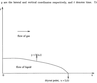
We assume that the film consists of an incompressible Newtonian fluid (since water has a low molecular weight, approximately 18.015 (Lide & Prederiskse, 1996 - 1997) [50], and is thus a Newtonian fluid (Skelland, 1967) [74]). The layer is evaporating so that at the vapour-liquid interface there is mass loss, momentum transfer and energy consumption. The vapour-liquid in the thin film is superheated and therefore non-boiling except at the free boundary where it is assumed to be at the saturation temperature. We also assume that initially the free surface is not disturbed, i.e. there is no rippling. Since ho/a < 1, we analyse a two-dimensional problem and neglect the effects of axisymmetry. Without loss of generality, we study the flow in horizontally orientated pipes. We employ Cartesian coordinates to describe the system; the schematic configuration is shown in figure (2.1). We assume that x = 0 corresponds to an initial measurement of the film thickness y = h(x,t), while x = L(t) corresponds to the dimensional length to the dryout point and is to be determined. The coordinates x and y are the lateral and vertical coordinates respectively, and t denotes time. Under
flow of gas
y =
[image:22.526.75.467.299.634.2]dryout point, x = L(t)
Figure 2.1: A schematic representation of the liquid-gas interface relative to the liquid film,
Navier-Stokes equations
UX+Vy = 0,
P (Ut + UUX + VUy) = ~PX + /i (UXX + Uyy) ,
p (vt + «ux + wy) = -pg-Py + n{vxx + vyy), (2.1)
where u and v are the a; and y components of velocity q of the liquid respectively and p is pressure in the liquid film. The constants p and /z are the density and dynamic viscosity of the liquid respectively, and g is the acceleration due to gravity in the system. Typical values for fi and p at the operating conditions of interest are approximately given by 6.44 x 10~5 N sec/m2 and 491 kg/m3, respectively.
2.3.1 Interfacial Mass and Momentum Balances
The equations are now closed by prescribing appropriate conditions at the boundaries. At the vapour-liquid interface y = h(x,t), there is a transfer of mass from the liquid layer into the gas core by a phase change at a yet unknown rate. On denoting the mass per unit area per unit time transferred from the liquid to the gas by M, and assuming that any mass escaping at the free surface does so in the direction of the outward-pointing normal of the free surface (since the mass in the tangential direction is not escaping, it is still part of the film free surface), we have (Delhaye, 1974) [24]
M = p ( q - < f c ) - n , (2.2)
where q^ is the velocity of the interface whose components are obtained from the kinematic condition of the free surface,
V{ = ht + Uihx, (2.3)
and n is the outward-pointing unit normal to the interface. In two dimensions, h is given by
Thus, in two dimensions M is given by
Hence the application of (2.3) yields
(l ) ~1 . (2.4)
therefore, if the surface tension is represented by an equation of state s = so — j(T — Ts)r
(where r = 1,2 e.g. r = 1, Pearson (1958) [60], Davis (1987) [22] and Burelbach et al (1988) [14]; r = 2, Oron & Rosenau (1994) [59]) for the surface tension gradient 7, for example, then s = SQ the surface tension at the saturation temperature of the liquid. It should be mentioned however, that surface tension may also depend on other scalar fields like the electrical field and the concentration of foreign materials on the interface (Levich &: Krylov, 1968) [48]; for simplicity we consider a clean interface here. With this assumption of constant surface tension, it implies that all the surface tension gradient terms are equal to zero. Thus, the shear stress at the interface effectively vanishes so that conservation of momentum tangential to the interface (Levich & Krylov, 1968) [48] yields
M(q-qs)-t-(T-Ts)-n-t = 0, (2.5)
where t is the tangential unit vector to the interface, q9 = (ug,vg) denotes the velocity in
the gas core and it is not yet known, Y and Tg are appropriate stress tensors of the liquid
and the vapour respectively. The term M (q — qs) • n is a reactive pressure at the interface known as vapour recoil (Burelbach et al, 1988; Bankoff, 1971) [14], [8] exerted by the vapour leaving normal to the interface. Both T and Tg are assumed to take an explicit form given
by
Vgx) fi (Uy + VX) 2flVy j
Vg {Ugy + Vgx) \
\ Hg (Ugy + VgX) J
That is, for simplicity, we have assumed that the flow in the gas core is also incompressible. The validity of the latter assumption will be justified later in section (2.4). We then define the tangential traction T(X, t) exerted on the free surface of the liquid film by the fast moving in the core by
Yg • n • t = —rt • t.
Thus, in two dimensions, r is given by
g (Ugy +Vgx)(l-kl)+ 2Hghx (v gy - UgX) } ( l + h\) , (2.8)
where \ig is the dynamic viscosity of the vapour. However, for simplicity, we will assume that
r is a known parameter even though this is not a necessary requirement. Therefore, the shear stress boundary condition at the interface gives
It should be noted that in deriving equations (2.8) and (2.9), we have employed a no-tangential slip condition at the interface y = h(x,t) in equation (2.5), i.e.
(q - qfl) • t = 0. (2.10)
It should be noticed that the validity of (2.10) holds since neither of the two fluids has been assumed to be inviscid at this stage.
The normal stress boundary condition at the interface balances the normal stress with the product of surface tension times twice the mean Gaussian curvature of the interface (Atherton & Homsy, 1976) [5] so that
3
*, (2.11)
where pg(x, t) is pressure in the gas core and is yet to be determined. In two dimensions
equation (2.11) leads to
jp (-uhx - ht+v) [-hx (ug - u) + vg - v] - 2/x \yy + uxh2x - hx (uy + vx)] j
x (l + hi)'' + N - (p -pg) = sQhxx (l + hi)'1 , (2.12)
where N is given by
N = 2fJ,g {Vgy + Ug^ - kX (Ugy + VgX) } ( l +
Finally, on the solid surface y = 0, the no-slip condition implies
u = v = 0. (2.13)
(It might be important to recall at this stage that M is still not yet known. A constitutive equation for M is derived in terms of h in section (2.6).)
2.3.2 Nondimensionalisation
In order to compare terms we need to nondimensionalise the variables. Depending on the choice of a timescale, this will lead to various nondimensional models. In the liquid film we set x = LQX, y = eLoy, h = eLoh, u = Uu, v = eUv, and p = (pU2/e2Re)p, where LQ
With these scalings, only two timescales, each determined by the boundary condition (driv-ing the unsteadiness of the problem) at the onset of the annular flow (x = 0), are enough. This point will be reiterated again later in this chapter in section (2.6). We first develop our models in detail under the fast timescale t = (Lo/U)i, and at the end we state and discuss the models under the long timescale t = (La/eU)i. With the fast timescale t = (Lo/U)i, equation (2.4) becomes
M = peU {-hxu - hi + v) ( e ^ l + l ) " , (2.14)
and therefore to lowest order in e we have
M = pUe {-hxu - hi + v). (2.15)
This effectively fixes the order of magnitude of the mass exchange required to produce dryout in an order L(t) distance. On defining the nondimensional rate of mass flow m by M = pUem, (2.15) becomes
rh= (-hsu - hi + v). (2.16)
In general, equation (2.16) is not valid at the tip where the assumptions of the thin-layer lubrication theory break. There, the velocities in the x and y directions are comparable. Therefore, the problem would need some new scalings near this point. However, for simplicity, we will assume that (2.16) is valid up to the dryout point.
In order to proceed with the analysis of equation (2.16) we need expressions for u and v in terms of h. These may be obtained by solving (2.1) subject to (2.9), (2.12) and (2.13). With the above scalings, the nondimensional problem to solve is
UX+Vy = 0,
e2Re (ui + uux + vv,y) — -px + e2uxx + Uyy,
e2Re (vf + uvx + vvy) = —g 1 + e2vxx + Vyy, (2-17)
£
subject to the boundary conditions
\(uy + e2vx) (l - e2h2x) + 2e2hx {vy - ux)\ (l + e2hf) ~1 = f, (2.18)
\pU2 (-uhx -hf + v) \-hx (eiig - e2uj + [yg - e2ujj
2/J.U r 3 - 7 2 t (- 2- M 1 (-, 2I2N\~1 — levy + e uxhx - ehx I uy + e vx)\ > 11 + e hx)
eLg L \ /J j \ /
+N - 4irP + ePooUlfg = Sehxx (l + e2hf) ~'2 (2.19)
on y = h(x,i); and
on y = 0. The nondimensional quantities g, N and r are defined by g = (e2ReLo/U2) g,
N = {2/j.gUoo/Lo) N and r = (fiU/eLo)f, respectively. The dimensional variable N is given by
N = 2-^ {v9S + e2h2ugi - ehs (ugy + vgi)} (l + Sh2)'1,
where, in the gas core (cf. section (2.4)), the variables x, y, pg and qs are respectively scaled with x = LQX, y = Loy, q9 = C^ooQg ~ €~lUqg and pg = epooll^pg. The dimensional
parameters Uoo, Poo and /J.^ are respectively the typical speed, density and dynamic viscosity of gas far upstream of the dryout point. It should be emphasised though, that the scalings for T are correct only when fi(U/efj,gUoo) ~ O(l), which can be confirmed, by considering
the typical parameter values given in the nomenclature table, that fi(U/engUoo) ~ 9.58. The
surface tension so has been scaled with SQ = (3/iC//eLo)so following several studies of capillary phenomena (see for example Williams & Davis, 1982) [94] where the surface tension is usually scaled with the thickness of the liquid film. We will comment further about the scaling of the surface tension in section (2.6). The nondimensional parameter 5 = (eLo/fiU)so is an inverse capillary number and is therefore a measure of the importance of surface tension effects.
2.3.3 Thin-Layer Lubrication Analysis
Examining the orders of magnitude of the dimensionless constants involved, we find that (approximating LQ using Lt ~ 6.1 m - the length of the tube that is heated) e ~ 1.64x 10~4 and e2Re ~ 0.012, so that a thin layer analysis is appropriate, pU2 ~ 0.049, fiU/eLo ~ 6.54 x 10~4, VgUoo/Lo ~ 6.85 x 10~5 which are small too, pU2/e2Re ~ 4.08 and epgll^ ~ 4.04 which are
both 0(1) and thus suggesting that to the leading order pressure is continuous across the interface. The gravitational term g ~ 1.18 (which is of 0(1)) and thus e2g ~ 3.17 x 10~8 is small. (It should be mentioned that even though we develop our models solely for the case of horizontal pipes, it will be shown later however that even for vertical pipes the models, with appropriate definition of variables, still hold.)
To leading order we therefore have to solve the familiar nondimensional lubrication equa-tions
us + vv = 0, (2.21)
fi = Uyy, (2.22)
Py = 0, (2.23)
subject to the boundary conditions
uy = T, on y = h(x,i), (2.24)
and
In addition, p = p(x, t) is continuous across the interface and hence will be determined by the dynamics in the gas core.
On solving (2.21), (2.22) and (2.23) for u and v subject to conditions (2.24) and (2.25) we obtain
« = Ipxy (y ~ 2h) + f y,
) + TiPxy hx — —Txy • (2.26)
u 2 2
Substituting (2.26) into (2.16) we get a nondimensional equation for h in terms of rh
1 3 •*• - 1 2 \ t In o-7\
ti Tn I — /if, (L.Zl)
where p$ is to be derived in section (2.4).
2.4 Gas Core Flow
In order to find an expression for px in terms of h and therefore close equation (2.27), we
have to take into account the flow in the gas core. We assume that in the gas core, far away from the interface, the gas is inviscid (this assumption is discussed further later on in this section). In addition, velocities are much higher in the vapour core than in the liquid film (Prosperetti & Plesset, 1984) [67]. Hence the changes in the vapour density originating at the liquid-vapour interface are quickly convected away from the interface. As a result, we take the vapour density as a constant in this study so that we have an incompressible flow of gas in the core. Essentially, in the gas core, we assume an inviscid and irrotational incompressible flow of gas in which the Bernoulli equation
-gy + — = C(t), (2.28)
holds, for some function C(t). We treat the flow in the liquid film adjacent to the pipe wall as a perturbation to the main flow in the gas core (see Figure (2.2)). The function $(x, y, t) is the velocity potential of the gas and therefore, the velocity components ug and vg respectively
satisfy ug = (j)xa.ndvg = <fiy. All other variables are as defined earlier, but are written with
a subscript g to signify their reference to the gas. Since the flow in the gas core is inviscid and irrotational, it satisfies the Laplace equation
<t>xx + <t>yy = 0 . (2.29)
y>
v
z4> = o
flow of gas
dryout point, x = L(t)
the fast flowing gas in the core provides a tangential traction on the liquid film free surface; therefore the gas cannot be totally inviscid. We can expect, due to viscous effects, that adjacent to the liquid film free surface there is a thin gas-flow viscous boundary layer. The traction (in general a function of x and t) that is supposed to be produced by this boundary layer on the liquid film is alternatively provided by the traction parameter T as explained earlier in section (2.3). Furthermore, on assuming that the liquid film is sufficiently thin and streamlined in such a way that separation cannot occur then we can treat the rest of the gas in the core as inviscid (Newman, 1977; King & Tuck, 1993) [56], [45]. It should be pointed out that in reality the flow in the gas is turbulent, see for example Kirillov et al (1985) [46]. However, as a first approximation which captures the modelling and analytical study of this problem we adopt, for simplicity, a laminar flow.
2.4.1 N o n d i m e n s i o n a l i s a t i o n
We now proceed by nondimensionalising the variables in the gas core. It is appropriate to set pg = epooU^pg, x = Lox, y = Loy, ug = J7oo%, vg = U^Vg, h = Loh, t = (L0/U)t ~
(Lo/eUtx)! and cj) = LoUocifi, where, as mentioned earlier, the dimensional parameters Uoo and Poo are respectively typical speed and density of the gas upstream of dryout, far away from the perturbation. This gives
Pgx = - \j>xt + t~l [UgUgS + VgVgx]) , (2.30)
from Bernoulli's equation (2.28), and
<Pxx + 4>yy = 0 , (2.31)
from the Laplace equation (2.29).
We now have to specify appropriate boundary conditions. Far away from the perturbation, the disturbance must vanish hence we must have
4>x -*• 1, 4>v ->• 0, as x2 + y2 -> oo. (2.32)
On y = eh(x,t), mass conservation dictates that
M - -Pg (q9 - q i) • n. (2.33) In two dimensions, to leading order, equation (2.33) leads to
M = -pgUg {-ehxug - e2hi + uff) . (2.34) We know, from section (2.3), that M = pUerh. We use this fact and a consistent approxima-tion Ug ~ U/e (as seen earlier in section (2.3)) to write (2.34) as
where we recall that ug = <j>x, vg = (f>y and (see the nomenclature table) p/pg ~ 2.87 which is
2.4.2 Thin Aerofoil Theory Approximation
We now seek an asymptotic expansion of the solution to (2.31) as the thickness parameter e —> 0. In the limit, the liquid film thickness reduces to a line y = 0 which causes no disturbance of the flow in the gas core. Thus, the basic solution is the uniform parallel flow with speed Ug. We therefore expect ^ to be of the form
4>(x,y,t;e) = x + e4>i{x,y,t) + e2f c ( x , y , *) + •••• (2.36)
We adopt standard thin aerofoil theory assumptions (see for example Van Dyke, 1975; New-man, 1977) [88], [56]. We calculate (2.36) at the free boundary y = eh(x,i). On assuming that all the 4>i{x, y,t) (i = 1, 2, • • •) are analytic at y = 0, we then expand the right hand side of (2.36) in Taylor series to obtain
4>{x,eh,t;e) = x + e^i(x,0,f) + e2 ^ ^
It then follows that
fe = 1 + 6 ^ ( 5 , 0 , t ) + e2 [ J W is( s , 0 ,
Hence equation (2.35) gives
- e2/ it- - e hs [1 + e<j>ix{x,y,t)-i ] + e(j>iy{x,y,i) + e2 [hy4>\y{x,y,
h4>ly-y(x,y,t) + 4>2{x,y,t)] + - - - + e2— m = 0, (2.37) Pg
at y — 0. The velocity potential 4>(x, y, t; e) in (2.31) thus satisfies, to order e,
4>lxx + <i>lyy = 0,
subject to the boundary conditions (from (2.32) and (2.37) respectively)
4>ix = 0, fay = 0, as x2 + y2 ->• oo,
<piy = hx, on y = 0.
By representing the interface y = eh(x,t) as a distribution of sinks and sources along the x-axis, an appropriate velocity potential for the gas flow is given by
I /-i+/(f)
where /(£,£) is unknown and has to be determined. It has been assumed, for simplicity, that L(i) can be written as L(i) = LQ + G{t) for some function G{t). Therefore l(t) is denned by l(i) = G(t)/Lo and it is also not known at this stage. It should be mentioned that L{t) may be written in other forms; however the current form is convenient for the linear stability analysis of this problem that takes place later in this thesis.
The mass conservation at y = eh(x,t), equation (2.33), warrants some comment. In the light of the above systematic analysis, (2.33) suggests that, since M is O(e) and the flow velocity is much higher in the gas core than in the liquid film then as far as the gas core flow is concerned, the interface y = eh(x,t) is a streamline. Thus the boundary condition that must be imposed is
—e2hf — ehx<f>x + 4>y = 0, a t y = eh.
On differentiating fa in (2.38) with respect to y we obtain
Or - £ )2 + y2
Taking the limit of (piy as y —> 0 and applying the boundary condition at y = 0 we get
( 2'4 0 )
where (2.40) is obtained from (2.39) by observing that as y —> 0 the integrand tends to zero except for the point £ = x. At this point, the integrand tends to infinity. Thus, y {(x — £)2 + y2}~ behaves like a delta Dirac function and hence we obtain (2.40). It then
follows that ug and vg respectively satisfy
() hc(f:
lim s = 1 + - 4 *Kq';d£, (2.41)
7T J-oo X — 4
= - lim fay — ehx(x,i), (2.42)
7T J / » 0
7T
where /-denotes a Cauchy Principal Value integral. Therefore, from equations (2.30), (2.41) and (2.42), on assuming that hx(x,t) = 0 for x < 0, an expression for pgx is given by
Therefore, to lowest order, the equation for the dimensional pressure gradient in the gas core
^ { i ^ y a ) )
(2
.
43)
The assumption that hx(x,t) = 0 for all x < 0 warrants some discussion. This assumption implies that at all times the film layer is flat for all x < 0. This is obviously untrue as it has already been discussed earlier that prior to the annular region, there are some several complicated flow regimes. We however argue that, since the annular flow regime occupies most of the boiler tube, there should be a point along the pipe where the annular flow regime is of constant thickness (even if it was not flat, but the shape was known, then this could easily be included). Therefore, for practical simplifications, we measure the length to the dryout from this point. This assumption will be revisited again later in the analysis.
2.5 Shear Stress Constitutive
Law-Concerning a constitutive equation for the tangential stress r, we will assume here (in order to keep the amount of algebra manageable when computing the solutions to this problem later in this study) that r (and hence f) is a known prescribed constant. A constitutive equation that has been adopted in the literature is a simple law r = fgwPocU^/2 (Thwaites, 1960; Sadatomi et al, 1993; King & Tuck, 1993) [85], [71], [45]. With the current scalings then the nondimensional shear stress would be f = fgweLopCK1U%0/2[j,U. The parameter fgw > 0,
in the thin layer approximation, is the coefficient of friction of steam on the wet pipe wall. Since f is expected to be of order 1, it then implies that fgw should be small. In general,
fgw is not known. It may however be determined empirically and experimentally for different
materials in various conditions of interest (see for example Whalley, 1987) [92]. In a general case under the current conditions, the constitutive equation for the dimensional r should be given by equation (2.8)
[(ugy + vg£) ( l
-Expressions for ug and vg at the unknown liquid free surface are obtained from the thin
aerofoil theory, equations (2.41) and (2.42) respectively, so that to leading order
r =
Thus the nondimensional f, under the current scalings, should be given by
T =
fill n
It can be confirmed from the parameter values given in the nomenclature that \xgl\i ~
2.6 Mass Transfer Constitutive Law
We proceed to complete the development of the equation (2.27) for a general mass exchange rate m. In general, rh depends on the details of the flow conditions and we will calculate these using simple thermodynamics models.
We assume, for reasons explained earlier, that the transfer of mass from the liquid film to the gas core is mainly affected by the evaporation process, i.e. deposition and entrainment are ignored. We further recall that the liquid in the thin film is superheated, hence the mass transfer is due to convective boiling (Whalley, 1987) [92] in which heat is transferred by conduction and convection through the film and evaporation takes place at the liquid-vapour interface. Thus, the interface is regarded as being at the saturation temperature.
On ignoring the viscous dissipation term, the flow of heat in the liquid film is governed by the equation
pCp (Tt + uTx + vTy) = k {Txx + Tyy), (2.44)
where the parameters Cp and k are respectively the specific heat and thermal conductivity of the liquid (typical values are given in the nomenclature table) and T denotes temperature. In reality, Cp and k will be functions of T but are assumed to be constants here for convenience and simplicity.
2.6.1 Robin Condition
We now have to prescribe appropriate boundary conditions for (2.44). The mass transfer is by phase change at the liquid-vapour interface y = h(x,t), hence, as mentioned earlier, we regard the interface to be at the saturation temperature T = TS. At the pipe wall y = 0, we
prescribe a general Robin boundary condition
kTy = - C ( M ) (r(M)ly=o -Trn) , (2-45)
where Tm is the typical temperature of the liquid metal, C(:c)^) is the heat transfer coefficient
which we regard as "known" and, for thermodynamic reasons (see for example, Babits, 1968; Sprackling, 1991) [7], [83], is required to be a positive quantity.
2.6.1.1 Nondimensionalisation
In order to compare terms in (2.44), we proceed by scaling variables using the thin-layer scalings x = Lox, y = eLoy, u = Uu, v = eUv, t = (L0/U)t and T = Ts + f(Tw- Ts), to
yield
where Tw is a typical wall temperature. On using the typical parameter values given in the
nomenclature table, it may be confirmed that
~ 32.76,
~ 8.81 x 1(T7.
Thus to the lowest order, equation (2.46) reduces to
Tyy = 0. (2.47)
In nondimensional variables (2.45) is
fy = -V(x,i), (2.48)
where V(x, t) is defined by
On solving (2.47) subject to (2.45) and T = Ts at y = h(x, t) we obtain
f = V(x,t)(h(x,t)-y).
2.6.2 Stefan Condition
The change of phase as the liquid boils at the interface must now be considered. On assuming that the temperature in the gas core remains constant and neglecting the surface entropy term, the standard Stefan condition (see for example Rubinstein, 1971) [69] asserts that
&«! = -P§i (V - h{x,t)) [x + \ ({(qff - m) • n}2 - {(q - <*) • n}2)} , (2.49)
where the square brackets indicate the jump in a quantity from the liquid to the gas side, A is the latent heat of vapourisation of the liquid (typical value is given in the nomenclature table), D/Dt = dt + q • V is the usual material derivative and, we recall, q^ is the velocity of the interface. Physically, this condition says that the thermal energy, which is conducted to the interface from the liquid side, is partly conducted away into the vapour and in part used to cause the phase change.
2.6.2.1 Nondimensionalisation
On invoking the thin-layer scalings x = LQX, y = eLoy, h = eL^h, u = Uu, v = el/v, t = (L0/U)t and T — Ts +T (Tw - Ts) to nondimensionalise variables, equation (2.49) becomes
y = -(v- uh ~ hi) L + ^ ^ [Ul (-ughs + vg- h? ~ U2 (-uhs + v - ]
where 7? = (UpLo\e2/k (Tw — Ts)) is a nondimensional parameter which, as the analysis will
show, characterises the transfer of mass from the liquid film into the gas core. From the typical values given in the nomenclature table, we observe that
~ 2.46 x 10"7,
- 6.59 x 10~15. 2 2
e3p£ot
Hence, to the leading order, Ty is given by
f9 = -r)(v- uhx - hi) • (2-51)
We recall, from equation (2.16), that m = v — uhx — /if, therefore we conclude from (2.51)
that
m = - - . (2.52) Finally equations (2.48) and (2.52) give
m = V^X'1'. (2.53)
V
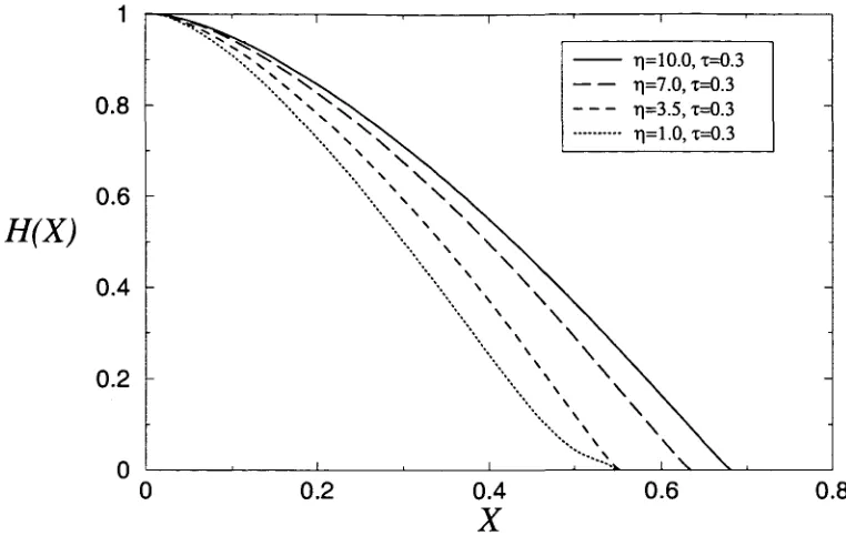
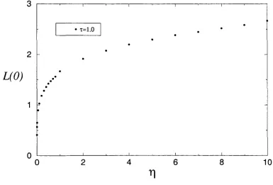
Equation (2.53) is a mass transfer constitutive law. It relates the interfacial mass flux m to the heat transfer coefficient at the boundary pipe wall. It thus confirms that the parameter r) indeed characterises the mass transfer from the liquid. For r\ 3> 1, i.e. a liquid with large latent heat, the mass transfer is small and dryout may not occur. For liquids with small latent heat, the mass transfer is so great that a liquid film may not be established and dryout occurs immediately. For the operating conditions of interest, the typical parameter values given in the nomenclature table imply
1.18
V ~ Tw-Ts'
indicating that with a few degrees of superheat in the liquid, dryout will occur at an 0(1) distance from the inset of the annular flow.
2.7 The Full Model
Since both the mass transfer and the shear stress constitutive laws are now known, then the final full nondimensional problem that must be solved, from equations (2.27), (2.43) and (2.53), is
T) X-7T \ In f — r I 9
' ^ \ / X ) X
easily be verified by following similar analysis as above). In this case, equation (2.54) reduces to
ZJ^ffMJ^) _£,} .
(2
.
55)
2 j
It may also easily be verified that timescales greater than t = (Lo/U)i are not allowable in the current model. In such cases M S> 0(1), relative to the liquid film. Physically, this means that the layer does not form at all.
For vertical pipes, it can be shown (by going through similar analysis as above) that under the current conditions of interest and appropriate redefining of variables, we obtain models very similar to (2.54) and (2.55). That is to say, in the fast timescale t = (LQ/U)1 for example, the final equation that must be solved is
where in this case x refers to a vertical Cartesian coordinate and y denotes the lateral ones. It is evident from (2.56) that in this case the gravitational term g is important. It should be mentioned however, that solving (2.56) cannot be mathematically different from solving (2.54) as the constant g can be absorbed into the traction parameter f. Henceforth we assume that f includes the effects of gravity.
As a final comment on (2.54), we consider what would happen if surface tension was to be included. In section (2.3), in order to keep the surface tension in the problem, we could scale the surface tension SQ with SQ = (3fiU/e2Lo) so instead of SQ = (3^iU/eLo) so- Thus, in the
fast timescale t — (Lo/U)t, to leading order the normal stress boundary condition (2.19) at the interface y = h(x,i) would become
-p + Cpg = Shxx,
where C and S are respectively given by C = e3Rep00U%0/pU2 and S = Se2Re/pU2. From
the typical parameter values given in the nomenclature table in the appendix, it can be confirmed that C ~ 1.01 which is of 0(1) and 5 ~ 4.01 x 10~55 (which suggests that the inverse capillary number S has to be very large in order that surface tension effects are important in this problem). The thin aerofoil analysis in section (2.4) together with equations (2.53) and (2.27) lead to a nondimensional equation for h
VjC-
h* (f MiJU - | 4 - % - f (S'iU)., (2.57,
V [ 3 7 r \ ^ y0 Z - x ) . 2 j . 3?r V I x
2.7.1 Heat Transfer Coefficient Constitutive Laws
For practical purposes, a constitutive equation for the heat transfer coefficient V(x, i) in equation (2.53) must be proposed in order to make any progress with calculations on the full model (2.54) (or with (2.55), (2.56) or (2.57)). This may be tackled in a number of ways. Here we will consider a case where the temperature at the pipe wall is assumed to be a known function of x and t, i.e. T\ Q = T\y{x,t). Other ways would include the case when V(x,t)
is assumed to be constant (we will comment again about this case later in this section). We proceed here by solving equation (2.47) for T. As mentioned earlier, we assume the temperature at the wall y = 0 is a known function of x and t, T\ 0 = T\y(x,t). Solution of (2.47) subject to T = Ts on y = h(x, t) and T = Tw{x, t) at y = 0 yields
In this case, (2.52) gives
(Tw(x,t)-T,\ 1
m={ Tw-Ts )jh> (2-59)
where (2.59) is the constitutive law for the mass transfer. Thus, the constitutive equation for the heat transfer coefficient V(x,i) in this case, from (2.53), is given by
(2.60)
2.7.2 Constant Wall Temperature Problem
We suppose that in practice boilers, evaporators etc., are arranged in such a way that the wall temperature is as close to constant as possible (in circumstances where this might not be the case, another problem in the liquid metal should be solved). We therefore assume for simplicity that T\y{x,t) —Tw, so that (2.59) implies
m=-L (2.61)
rjh
which is singular at the dryout point h = 0. The final full nondimensional problem that must be solved, from equation (2.54), with V(x,t) given by V(x,t) = 1/h from equation (2.61), is then
T]h [3TT \JO Z-OC ) _ 2 j .
(2.65)
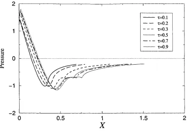
Evidently, the nonlinear singular nature of the above equations renders it extremely unlikely that it will be possible to find closed-form solutions. In the steady state analysis in chapter 3, we solve (2.62) using both asymptotic and numerical techniques. We will begin by considering some special limiting cases which will motivate a numerical method for the full problem. It will also be argued later, in the same chapter, that solving (2.65) numerically should not be fundamentally different from solving (2.62).
2.7.3 A Varying Wall Temperature Problem
As mentioned in section (2.7.2), in the case when the wall temperature is not constant then a problem in the liquid metal should be solved for temperature profiles. However, this is a non-trivial task. It requires careful modelling of the flow problem and the knowledge of pressure (which is in general a function of x and i) in the liquid metal. Further, in some cases (see for example, Ockendon Sz Ockendon, 1977; Pearson, 177) [57], [61] it may be appropriate to propose a constitutive equation for the liquid metal viscosity (which is in general a function of temperature). It is extremely unlikely that the resulting model could be solved in closed-form. Hence, it is unhelpful for the current purpose. An outline for this problem, in the current conditions of interest, will be briefly presented in section (2.8). Here, we observe that if the temperature at the pipe wall is given by
lw\X,t) = J-s + [J-w — ±s)n j
(in which case V(x,t) is given by V(x,i) = h(x,t)) then from (2.54) we obtain
T) ~ \ 37T \J0
This problem may not have any obvious physical relevance whatsoever (though it will be seen that the results for this case are realistic). However equation (2.66) is relatively simpler to solve (as it will be seen later in this study) than both equations (2.62) and (2.67). Hence solving (2.66) encourages different numerical techniques (which are tackled in chapter 4) for these types of problems. Further, the steady state solutions to (2.66) help us to explain some of unexpected behaviour in the numerical results (in particular, the pressure profile curves) of equations (2.62) and (2.67).
2.7.4 Constant Wall Heat Flux Problem
the known properties of the total heat input provided by the reactor. It is questionable how such a pointwise heat flux may be either measured or maintained, or whether it is reasonable to assume that it does not change along the tube. However, if such is the case, then the equation that must be solved, from (2.66) or (2.54), is
where the nondimensional heat transfer coefficient V(x,t) is simply a constant and has been absorbed into the heat mass transfer parameter 77 in equation (2.67).
2.7.5 Initial and Boundary Conditions of the Full Model
The modelling formulation must be completed by the specification of appropriate initial and boundary conditions. The boundary conditions for this problem are far from trivial. To begin with, it should be observed that (2.62) [or (2.66) or (2.67)] requires the prescription of at least four boundary conditions (the reasons for this will become clearer as we discuss these conditions further in the particular case in chapter 3). At the dryout point, where the liquid film vanishes at all times, the obvious boundary condition to impose is that h(r(t)) = 0. The function r(t) is not known a priori. We require that h(x, i) ~ (r(i) — x)p as x —> r(t), for the
appropriate real value p to be determined as part of solution. We assume that at the onset of the annular flow x = 0, h(O,t) is known at all times t. It is convenient to assume that h(O,t) is a constant equal to ho (say) for all t. Another boundary condition may be obtained by assuming that in practice the pressure at x = 0 can be measured and therefore it is known. Equally, we may require that JIQ satisfy the pressure gradient condition (which is obtained by insisting that the mass flux should always vanish at the dryout point) at x — 0. The final boundary condition comes from the fact that we do not allow infinite values of pressure at x = 0 so that hx{0,t) = 0 (again this condition will become clearer as it is discussed further in chapter 3). As far as the initial conditions are concerned, it is sensible to assume that h(x, 0) = h(x), for some steady state solution h(x), and r(i) = 1 at t = 0.
2.8 Problem in the Liquid Metal
just set it up to show that it could be done. Figure (2.3) shows a schematic representation of the whole problem. For convenience, the dryout point is at x = 0 measured from the entry to
Flow of gas
y=0 Liquid film
x=0 u=v=0 T (x,t)
w x=L(t)
Liquid metal flow
y=-H
T=T (t)
E
u=v=0 T (x,-H)=O
Figure 2.3: A schematic representation of the problem in the liquid metal.
the annular regime at re = L(t). We assume, for simplicity, that the flow in the liquid metal has the characteristic velocity Um, constant density pm, constant specific heat Cpm, constant
thermal conductivity km, typical temperature Tm and dynamic viscosity fi(x,T) to account
for some essential coupling between the energy and momentum equations.
Considering the pipes (in which the liquid metal flows) whose typical length is approx-imately equal to the typical length of the steam generating pipes (6.1 m) and possess a characteristic diameter H ~ 0.012 m, we consider here a two-dimensional problem. For simplicity and to avoid unnecessary complications, we consider a quasi-steady state and in-compressible flow in the liquid metal. It is convenient to write L(t) as L(t) = LQ + SG(t), for some function G(t), LQ is the length to the dryout point in the steady state case and 8(> 0) is small and is defined by 8 = H/LQ. On approximating LQ by the characteristic length of the pipe then 5 ~ 1.97 x 10~3.
We now nondimensionalise variables by setting (thin-layer scalings but in a different layer) x = Lox, y = 6Loy = Hy, u = Umu, v = 5Umv, p = (pmU^l/82Rern)p, T = Tm +
T(TW - Tm) , t = (L0/8Um) i and n = nmp,(x,T) where Rem = UmLQpmj\im and fj,m are
two-dimensional Navier-Stokes equations for the flow in the liquid metal become Ux+Vy = 0,
S2Rem {Suf + uux + vuv) = -px + 62 {fi(x,f)us)- + (/2(z,T)u5)_ Vy) = -g - ^ | + 82 {ji{x,T)vx) (x,f)vs).,
where the nondimensional parameters g, A and B are respectively given by
A =
and
82RemL0
"-T71
~
g^~uir
g'
(Tw-Tm)L0'
where g is, as usual, the acceleration due to gravity and Tw is the typical temperature of the
heated pipe wall at y = 0. In the energy equation, only the dominant term (uy/8)2 from the
viscous dissipation term has been included.
In order to suggest the qualitative details of the flow in the liquid metal, typical orders of magnitude for 52Rem, A and B are required. However, getting typical parameter values is not
easy for this problem. In this section, all the typical physical parameter values for the liquid metal have been taken from Bolz & Tuve (1973) [13] (different sources in the literature may give different values). At typical operating temperatures of 673 K, the physical parameter values for liquid sodium are typically given by Cpm ~ 1280.30 J/kg/K, pm ~ 858.56 kg/m3, km ~ 71.09 W/m/K, p,m ~ 2.85 x 10"4 Ns/m2 and Tm ~ 673 K while Tw ~ 640 K. Therefore,
for a typical velocity of Um ~ 0.1 m/s in the liquid metal, A ~ 1.06 x 10~4, B ~ -7.86 x 10~13 and thus B/62 ~ 2.01 x 10~7 (which is small) while A/82 = A ~ 27.31 (and it is of 0(1)).
The parameters 82Rem and g are typically (and respectively) given by 82Rem ~ 7.13 (which
is of 0(1)) and g ~ 713g, where the magnitude of g is g ~ 9.8 (hence 82g ~ 2.77 x 10~3# and it is small).
Therefore, to leading order, the Navier-Stokes equations reduce to
ux + vy = 0, (2.68)
uux + vuy = -px + (fl(x,f)uy)v, (2.69)
Py = 0, (2.70)
UTX+VTy = ATyy. (2.71)
(i.e. the outer casing wall is assumed to be totally insulated). Finally, we assume that both the dimensional pressure and temperature, PE{1) and TE(<) respectively, can be measured and therefore are known at the entry to the annular regime x = L(t). The dimensional temperature T — Tw{x,t) at the pipe wall y = 0 is unknown and it has to be found. Since p.(x,T) in equation (2.69) does not appear in the energy equation (2.71), then it is reasonable and convenient to treat it as a constant and ignore the dependence on x.
The system of equations (2.68) - (2.71) is very challenging to solve numerically (due to nonlinearity and coupling of some dependent variables). However, we observe that when the flow in the liquid metal is a fully developed Poiseuille flow at all times, we can then write
for some function F(t). Then we obtain that v(x, y, t) = 0 so that the no-slip condition holds at the boundary walls. As a result, equation (2.70) tells us that the pressure p is a function of x and t only. From equation (2.69), in nondimensional form, we have
Px =
so that on integrating with respect to x we obtain
p = ™ F(t)x + a constant.
52L£
We apply the boundary contain p = PE(<) at x = L{t) to yield
Thus, in nondimensional variables, p is given by
to leading order. The nondimensional function PE$) is given by
The dimensional temperature T has to be obtained by solving (2.71)
F(t)y (jj + l ) Tx = ALoHTyy, (2.72)
subject to the boundary conditions Ty = 0 at y = —H, T = TE(£) at x = L(t) and T =
Chapter 3
Steady States for the Constant
Wall Temperature Problem
Prior to any attempts to solve the unsteady problem subject to appropriate initial and bound-ary conditions, it is instructive to analyse and try to understand steady state situations. Ow-ing to the nonlinear sOw-ingular nature of the governOw-ing equation, it is extremely unlikely that the problem can ever be solved in closed-form except for particular special cases. Therefore, it is inevitable that we have to resort to asymptotic and numerical techniques in order to obtain any information from the model. We start by analysing some paradigm problems, mainly to motivate an appropriate numerical method for the full nonlinear problem (steady state version of (2.62)) which will be tackled in section (3.2).
3.1 Limiting Cases and Paradigm Problems
We define M by M = Qx, where Q is the dimensional rate of mass transfer per unit length
at the free surface. In this case the dimensional version of equation (2.27) may be integrated, where we recall that in the liquid film M = pUem, x = LQX, h = eLoh, r = (I^U/CLQ) f,
p = (pU2/e2Re) p and Re = ULop/fi. On assuming that px is finite at the dryout point h = 0
(or if it is not, then at least it does not blow up faster than h3 tends to zero at this point),
we impose, for simplicity, the boundary condition Q = 0 t
![Figure 4.3: Plot of the length to the dryout LQ (= 1/(0)) against the mass transfer parameterr] with the traction parameter f = 0.0.](https://thumb-us.123doks.com/thumbv2/123dok_us/1042831.619957/94.526.82.462.63.306/figure-plot-length-dryout-transfer-parameterr-traction-parameter.webp)