ourth-generation wireless and mobile systems are currently the focus of research and devel-opment. They will allow new types of services to be universally available to consumers and for industrial applications. Broad-band wireless networks will enable packet-based high-data-rate communications suitable for video transmission and mobile Internet applications.
This article is based on a project that aims to develop a single-chip wireless broadband communication system in the 5 GHz band, compliant with the Hiperlan/2 [1] and IEEE 802.11a [2] standards. Both standards specify broadband com-munication systems using orthogonal frequency-division multi-plexing (OFDM) with data rates ranging from 6–54 Mb/s. Depending on the desired data rate, the modulation scheme adopted can be either binary phase shift keying (BPSK), qua-ternary PSK (QPSK), or quadrature amplitude modulation (QAM) with 1–6 b/subcarrier. The bandwidth of the transmit-ted signal is 20 MHz and the symbol duration is 4 µs including 0.8 µs for a guard interval.
To open a broad market for consumer products, low cost of the required hardware is essential. One way to realize low-cost systems is to reduce the system complexity and imple-ment all functions in a single chip. A single-chip solution is also advantageous in terms of performance and power dissipa-tion when compared with multichip implementadissipa-tions. Fewer wires have to be routed via slow and power-hungry pad drivers. In addition, short interconnections allow faster opera-tion of the system.
Our in-house 0.25 µm SiGe:C BiCMOS technology enables the integration of complex digital baseband and data link con-trol (DLC) functionality together with the analog RF front-end (AFE). Since the complete design flow, from system simulation down to working silicon, is on hand and under one roof, fast feedback is possible during the complete design cycle.
By simultaneously considering all layers of the protocol stack, we were able to optimize the system performance. The dynamic activation/deactivation of certain blocks during trans-mission and reception allows us to introduce efficient power reduction mechanisms.
In our vision, this broadband modem forms the communi-cation element for a single-chip wireless engine which in turn is the heart of a complete personal digital assistant (PDA). For that purpose we also intend to integrate a TCP/IP proces-sor and a Java-based application engine as well as advanced power management and test engines.
This article is structured as follows. We give a very rough estimation of the algorithmic complexity of various blocks in the baseband and DLC layer of the wireless modem. This allows a first evaluation of the computing resources required for the modem functionality. A discussion based on these results leads to the derivation of a suitable system architecture. Some aspects of the design flow used are highlighted. A set of required hardware and software tools is listed. Some results of our work are presented. Here we focus on the implementation of specific blocks within the digital baseband processor. We summarize our results and suggest further work.
Trends in 4G Wireless Communication
There is an increasing amount of discussion related to fourth-generation (4G) wireless systems that are expected to emerge quite soon after the deployment of third-generation cellular mobile systems. It is naturally too early to state anything firm on 4G, but we think that some general trends can already be seen in R&D. In our opinion the following aspects seem to be common themes and technologies for wireless 4G systems. First, it is believed that broadband data communication capa-bility is at least as important as voice communication. This has lead to the trend to use Internet Protocol (IP) as a generic
F
On the Single-Chip Implementation of a
Hiperlan/2 and IEEE 802.11a
Capable Modem
Eckhard Grass, Klaus Tittelbach-Helmrich, Ulrich Jagdhold,
Alfonso Troya, Gunther Lippert, Olaf Krüger, Jens Lehmann,
Koushik Maharatna, Kai F. Dombrowski, Norbert Fiebig, and
Rolf Kraemer, IHP-GmbH
Petri Mähönen, University of Oulu
Abstract
Broadband wireless communication is the key technology to a new generation of products in the consumer market. The emerging standards for the 5 GHz band will form the basis for many applications requiring high communication bandwidth. Low cost and low power dissipation
will be a prerequisite for most mobile applications. One way to realize low-cost systems is to reduce the system complexity and deploy highly integrated components. The work presented in this article discusses aspects of implementing a complete Hiperlan/2 and
protocol technology. Second, 4G networks will be het-erogeneous multitechnology systems, where different networks must be able to interoperate and should be designed to be “polite” to each other (e.g., they should cause as low interference as possible to other wireless devices). Third, there is still an increasing demand for faster broadband wireless networks. In our opinion outdoor bit rates will be over 100 Mb/s and in some cases the bit rates could be even in the order of 1 Gb/s in the future. Fourth, the requirement to support wireless ad hoc networks and zero configurability have high priority with 4G systems. Finally, it is highly pos-sible that the future 4G infrastructure is not built just around macrocellular (e.g., Universal Mobile Telecommunications System, UMTS) and microcellu-lar (e.g., wireless LAN, WLAN) technologies; person-al and body area networks (PANs and BANs) will person-also become very important. This is leading to a prolifera-tion of small, cheap, high-bit-rate system-on-silicon radio devices that are necessary for pervasive and ubiquitous computing.
The above mentioned common 4G trends mean that a lot of relevant research and development can already be done without knowing exactly how these future wireless systems and heterogeneous networks will evolve. Following the outlined trends, the indus-try is moving into higher frequency bands, starting to use OFDM, and increasing the integration level. Especially for ubiquitous network access it is impor-tant to provide efficient and cost-effective system-on-silicon platforms that are capable of providing high flexibility and performance. In order to be able to test some of the 4G networking issues with pre-sent-day technology and to provide an evolutionary path toward new solutions, we have studied the pos-sibility of providing an IEEE 802.11a and Hiperlan/2 compatible system on silicon. With respect to the physical layer (PHY) these standards are quite simi-lar, but on the medium access control (MAC) layer they are largely different. The IEEE 802.11 standard defines a carrier sense multiple access with collision avoidance (CSMA/CA)-based “wireless Ethernet” system; Hiperlan/2 is a connection-oriented
time-division multiple access (TDMA)-system. Potentially there is a great advantage in providing both Open System Intercon-nection (OSI) layers (PHY and MAC) on same silicon. Moreover, we believe that, using advanced SiGe:C BiCMOS process technology, in the future it will be possible to pack-age both communication and computing capabilities into a single chip. This would allow spreading these WLAN-type wireless computing engines all over the environment to pro-vide communications, automation, routing, and computing services. One possible use for this sort of high-bit-rate small chip is to work as a gateway to forward aggregated data from BANs and PANs to the Internet by using WLANs. This means that in the 4G paradigm we can support dense net-works, where fast WLANs at high frequencies (17 and 60 GHz) are available almost everywhere and in particular in high population density areas. This mass application of WLANs will lead to very competitive pricing.
We think that especially in the case of high-performance systems and/or consumer products, it is important to do an overall cooptimization between all relevant OSI layers of com-munication, instead of today’s separate optimization. Taking into account chip manufacturing and OSI layers 1–3 concur-rently not only leads to better optimized and cheaper chips, but also reduces the time to market. Finally, on the terminal
side, we believe that a software radio approach is becoming important in the 4G systems timescale. The functional blocks we are defining and developing can be reused for software-defined radio development.
Estimation of Algorithmic Complexity
Computational Requirements of the
Baseband Processor
Based on the IEEE 802.11a standard a C-model was devel-oped that simulates the functionality of the data path for baseband processing. The transmitter model consists of a baseband control unit, header insertion, parity generation, a scrambler, an encoder (rates 1/2, 2/3, 3/4, 9/16), an interleaver, a modulator, and a 64-point inverse fast Fourier transform (IFFT). Parity generation is necessary for protecting the signal field. In the receive direction the components of the transmit-ter are reversed consisting of a 64-point FFT, a demodulator, a deinterleaver, a Viterbi decoder, a descrambler, and a parity check. The OFDM synchronization unit was not modeled.
The software of the model (C-code) was implemented on a SUN Sparcstation 10 at 40 MHz (processor: MS390Z50) using
"Figure 1.Processing demands per OFDM symbol for a C model in a)
transmit mode and b) receive mode. (a)
Seconds
6 Mb/s 9 Mb/s
12 Mb/s 18 Mb/s
24 Mb/s 36 Mb/s
48 Mb/s 54 Mb/s 0.0035
0.0030
0.0025
0.0020
0.0015
0.0010
0.0005
0.0000
(b)
Seconds
6 Mb/s 9 Mb/s
12 Mb/s 18 Mb/s
24 Mb/s 36 Mb/s
48 Mb/s 54 Mb/s 3.0
2.5
2.0
1.5
1.0
0.5
0.0
MAC Descrambler Deinterleaver Demapper FFT Viterbi Sum
the standard C compiler (v. 4.0) from Sun Microsystems. For statistical reasons we transmitted 1024 bytes 500 times at dif-ferent bit rates ranging from 6–54 Mb/s. In Fig. 1 the process-ing time is plotted on the Y axis in seconds. This is the time the C program requires to transmit or receive a fixed number of OFDM symbols.
In transmit direction and for a constant number of symbols the overall processing power will be increased only slightly if the bit rate increases from 6 to 54 Mb/s, as can be seen in Fig. 1a. This is due to the increased number of bits per subcarrier. A second observation is that in all cases most of the process-ing power will be needed for the IFFT. Since the IFFT is dominant, and always one IFFT has to be performed per sym-bol, the increase of total processing power plotted against data rate is relatively small.
In the receive direction the Viterbi decoder consumes most of the calculation power, as shown in Fig. 1b. The fraction of the total time used by the Viterbi decoder
reach-es from 98 percent at 6 Mb/s up to 99.9 percent at 54 Mb/s. The remaining 0.1–2 percent pro-cessing power is shared by all other functional blocks.
Our calculations demonstrate that the pro-cessing power of the IEEE 802.11a system is dis-tributed in an asymmetric fashion between transmit and receive operations. This is caused by the overwhelming cost of the Viterbi decoder on the receiver side. As illustrated in Fig. 1, the distribution of the processing power between transmit and receive mode also depends on the data rate used. Due to the dominance of the Viterbi decoder in terms of processing require-ments, a hardware implementation is necessary for our application.
DLC Profiling for 802.11
Some hints concerning the required processing power within the DLC layer in an IEEE 802.11 system can be obtained from available systems. The chip Am79C930 from AMD [3] implements the IEEE 802.11 MAC on the basis of an 80188 processor clocked at 40 MHz. Intersil has devel-oped the HFA 3842, a MAC processor for the
2.4 GHz direct sequence spread spec-trum (DSSS) physical layer of IEEE 802.11b [4]. This chip supports sta-tion funcsta-tionality with data rates up to 11 Mb/s. The external clock runs at 44 MHz.
[image:3.585.249.545.488.717.2]We have developed a complete abstract simulation model for IEEE 802.11 using the Specification and Description Language (SDL). When simulating this model using Telelog-ic’s SDL simulator, about 50 percent of the processor power is required for the SDL runtime environment. Figure 2 shows the contribution of the different SDL processes of our model in the remaining 50 percent of the processor power, which is spent for executing the user code. The soft-ware cyclic redundancy check (CRC, only needed in SDL processes TxAddFcs and RxCheckFcs) domi-nates the required processing capaci-ty using a total of 75 percent of the available resources. The process ChannelState, which is responsible for monitoring the idle or busy state of the radio channel, consumes the second most processing power after CRC. This is due to the backoff procedure running in this SDL process. The control processes AuthService and Assoc-Service are only called on demand, that is, very rarely. The same applies to the process MIB, responsible for setting and reading the station’s management information base.
Encryption, which would be even more expensive than CRC, was not used in this example.
Although we don’t have absolute figures for the required processor performance, the following conclusions can be drawn from our simulations of an IEEE 802.11 system: • A station only capable of distributed coordination function
(DCF) requires modest processing power. The most time-critical task is the generation of the acknowledgment frame within 16 µs.
"Figure 2.Relative processing requirements of the DLC processes of our 802.11 SDL
model when not using encryption. 0.07
Percent processing time
MIB
AuthServiceAssocService
SynchronizationChannelstate
TxAddFcs TxQueueTxArrangeRxCheckFcs RxFilterRxComplete
5 10 15 20 25 30 35 40 55 50
0
0.01 0.02 1.43
CRC
5.17 42.60
2.65 2.52 1.03 0.36
44.14
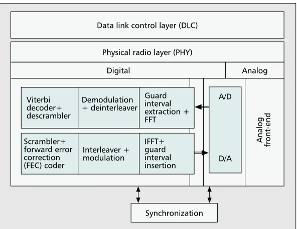
"Figure 3.The structure of a wireless broadband modem using OFDM.
A/D
D/A Viterbi
decoder+ descrambler
Guard interval extraction + FFT Demodulation + deinterleaver
Data link control layer (DLC)
Physical radio layer (PHY)
Synchronization
Digital Analog
Analog front-end
Scrambler+ forward error correction (FEC) coder
IFFT+ guard interval insertion Interleaver +
• For the access point of an infrastructure network using DCF, considerably more processing power is required (e.g., for generating beacons with a traffic indication map). • Most processing power is needed when using the optional
point coordination function (PCF). Any station must be able to respond with a data frame within 16 µs.
• CRC and encryption/decryption must be implemented in hardware in order to achieve reasonable performance.
From these estimates, we expect that the IEEE 802.11a MAC layer can be implemented in software on an ARM 7 processor with appropriate dedicated hardware accelerators.
The System Concept and
Main Parameters
The complete modem is broken down into three main blocks — the analog front-end including the analog-to-digital (A/D) and D/A converters, the digital baseband processor, and the DLC layer, as shown in Fig. 3.
In the following sections the system concept as well as cor-ner parameters of the main blocks are discussed.
Analog Front-End and Data Converters
For the implementation of the analog front-end three main topologies can be chosen. A possible solution is the “normal” super-heterodyne transceiver using one mid-range intermedi-ate frequency. This is the most conventional approach, which would require a narrowband filter at the center frequency of the IF. With the current technologies these filters can only be implemented using surface acoustic wave (SAW) devices. Using this approach, the I/Q separation can be done in the analog domain, which means that two A/D converters with an analog bandwidth of 10 MHz each are required. A block dia-gram of the super-heterodyne transceiver is shown in Fig. 4. The IF chosen in our design is 810 MHz. The required SAW
filters are also the main disadvantage of the super-het con-cept. With current technology they can only be added as external components to the mixed-signal chip, leading to increased cost and area. Furthermore, high-frequency signals need to be routed off-chip which leads to an increase in power dissipation.
Another possible strategy is to adopt a low-IF concept. With this technique costly SAW filters can be avoided. This allows moving the I/Q splitter from the analog domain into the digital domain. However, one disadvantage of this approach is that the analog bandwidth of the A/D convert-er has to be at least 20 MHz. This requires an attendant higher sampling rate of the A/D converter. Furthermore, additional circuitry in the digital domain such as a numeri-cally controlled oscillator (NCO) for the I/Q separation is needed. The specification of the (single) analog mixer also becomes tighter and demands extra effort in the analog domain.
A similar argument applies to the zero-IF (or direct down-conversion) concept. Here the RF signal is directly converted to baseband (i.e., the IF is zero). Any channel selection must be done on the baseband and/or digital signal processing (DSP) level rather than split into IF and baseband domains as with the super-het architecture. Additionally, one faces all the problems of signal dynamics that require much more effort and precision in the RF section. However, compared to the low-IF topology, only low pass filtering is necessary.
Even though in the long term both low IF and zero IF are more promising since no external SAW filters are needed, here we advocate adoption of the conventional super-het transceiver. This decision is the result of a risk assessment of the various techniques. Adopting a well-known transceiver architecture does reduce the probability of costly and time-consuming redesigns for the single-chip modem. However, in parallel to the super-het AFE we have started to design the zero-IF and low-IF topologies.
"Figure 4.A block diagram of the 5 GHz super-heterodyne transceiver.
LNA DNMIX1
PLL1 VCO
RXIFAMP DNMIX2I
SAW RXLPFI
RX-I RXAMPI
DIV
PA SW
PHA 1/N
90° 0° OSC
BFF
TXDR UPMIX1 SAW TXIFAMP
DNMIX2Q RXLPFQ
RX-Q RXAMPQ
UPMIX2Q TXLPFQ
TX-Q
TXAMPQ
UPMIX2I TXLPFI
TX-1
TXAMPI PLL2
For the super-heterodyne transceiver the data converters have a relatively relaxed specification. The two A/D convert-ers require at least a resolution of 3 bits (for demodulator) plus 4 bits (for soft decision input of the Viterbi decoder). Leaving three additional bits for digital adjustment of the dynamic range and to counter the arithmetic noise results in a total of 10 bits. The sample rate has to be at least 20 MHz (Nyquist rate). However, in our implementation, to simplify the design of the channel filter and interpolator (see a later section), a sample rate of 80 MHz will be used. A pipelined A/D converter architecture will be deployed to achieve the specification above.
In the transmitter we use two D/A converters having a res-olution of 10 bits and a sampling rate of 80 MHz as well. The main reason for oversampling by a factor of four is that the analog reconstruction filters can be designed with relaxed specifications.
Digital Baseband
Software Radio vs. Dedicated Hardware— Recently, the concept of a software-defined radio has attracted much atten-tion. However, we believe that for our application, even with the most advanced technology, a traditional software radio approach is not economically feasible. This is because the high data rates and complex algorithms require excessive computa-tional performance. Furthermore, both 5 GHz standards allow only very little latency in the baseband processor (in the order of 10 µs) in order to meet the timing constraints for sending acknowledgment frames.
Extremely high-performance DSPs, on the other hand, are also very expensive. Another aspect is their attendant power dissipation. On average, the power dissipation of a software solution is an order of magnitude higher than a functionally equivalent hardware implementation. The main advantages of a software-defined radio are flexibility and the possibility of reconfiguration. However, the advantages can only be exploited if the computational demands can easily be met with a low-cost processor. In our case either a multipro-cessor system or a promultipro-cessor with a number of hardware accelerators would have to be used. Therefore, we have decided to use dedicated hardware for the baseband process-ing. The function of transmitter and receiver lend themselves to a data path architecture. An additional dedicated con-troller to adjust parameters during transmission and recep-tion is also implemented in hardware. Configurability is achieved by using (embedded) field programmable gate arrays (FPGAs).
To decentralize some time-critical control functions, a token flow approach was adopted. Every block in the base-band processor has an input signal, which indicates that valid data is ready for processing. A similar signal is gener-ated by every block upon output to indicate that data can be processed by the subsequent block. The token flow approach can easily be enhanced with clock gating. This results in an efficient and easy to implement power saving mechanism.
Even though most blocks of the synchronization unit are not directly in the datapath a hardware implementation is advocated in order to meet the tight timing constraints. An embedded FPGA is used to allow modifications for certain specific applications.
The main differences between Hiperlan/2 and IEEE 802.11a are in the puncturing modes, the algorithm for scram-bler initialization and the selection of the appropriate data rate in the receiver. By allowing configuration of some func-tional blocks, the baseband processor can easily be designed to operate with both standards.
DLC-Layer
As discussed in an earlier section, the DLC layer will be implemented using hardware-software codesign. For the soft-ware part, we will use an ARM 7 processor that will be insert-ed as a synthesizeable core into the single-chip design. During system development, we used a NET+ARM™ development board from NETsilicon, Inc. The board has an integrated 100 Mb/s Ethernet interface that will be used for the interface between the DLC and the upper layers in the protocol stack.
The following DLC functionality will be implemented using hardware accelerators:
• CRC (32-bit in IEEE 802.11, 16 and 24-bit in Hiperlan/2, each processing 8 bits = 1 octet in parallel)
• System time handling and timers with a resolution of 1 µs (IEEE 802.11) or 0.4 µs (Hiperlan/2), respectively
• Optional encryption/decryption
During system development, the accelerators are realized using a programmable logic device (FPGA) connected to the pro-cessor test board. In the single-chip solution they will be designed in VHDL and synthesized along with the processor core.
Interface Definition
The interfaces of the modem correspond to the main building blocks: analog front-end (AFE), baseband (digital) part of the PHY layer (BB), and DLC layer.
AFE–BB Interface— This interface is represented by the D/A and A/D converters. Both converters operate at 80 Msam-ples/s with 10 bit resolution on both the I and Q channels. Furthermore, we will use a 3-wire bus to transfer some con-trol information from the BB to the AFE (e.g., for sleep modes and RF channel selection) and vice versa (e.g., the receive signal strength indicator, RSSI).
BB–DLC Interface— During system development, the inter-face between the physical layer and the DLC layer will proba-bly be implemented as an 8 bit parallel port similar to an EPP (enhanced printer port) interface according to IEEE 1284. For the highest system data rate of 54 Mb/s, the interface must operate at about 7 Mbytes/s. The interface design is intended to support both standards, IEEE 802.11 and Hiper-lan/2. Control data are also transferred via the EPP port.
In the single-chip design the data exchange between the PHY layer and DLC will be organized via shared memory.
Upper DLC Interface— This interface connects the wireless LAN to either a wired LAN such as Ethernet or asynchronous transfer mode (ATM), or an application running on a com-puter. In the first demonstrator we will use a 100 Mb/s Ether-net interface. A later version will employ a PCMCIA-card to connect to a PC. To transfer DLC control information at the upper interface, the Simple Network Management Protocol (SNMP) could be implemented and used.
Technology and Design Flow
Design Flow for the Analog Front-End
Our step-by-step approach is focused toward a single-chip RF front-end using IHP’s in-house SiGe:C technology. Conse-quently, the design flow is mainly based on our design envi-ronment. Circuits capable of handling the signals of interest are designed, laid out, and implemented in mainstream 0.25
con-verters, further analog circuits are needed to complete the analog front-end chip. Low-cost implementation is another issue for this kind of circuit, which implies the need for high-quality-factor passive components (inductors, varactors, etc.). These are difficult to realize monolithically in silicon. This is even more so if only standard CMOS technology is available. Our in-house 0.25 µm SiGe:C BiCMOS process constitutes an ideal platform for system-on-chip design and for implement-ing the Hiperlan/2 and IEEE 802.11a modems. Radio fre-quency AFE and DSP integrated in one chip will be the challenge for future designs.
Design Flow for BB
After having done a rough profiling of the computational demands of the baseband processor on the basis of a C pro-gram, an application-specific integrated circuit (ASIC) design flow was deployed.
For the algorithmic verification a complete model using Cadence’s Signal Processing Worksystem (SPW) has been generated. The main blocks of the SPW model are then mod-eled in synthesizable VHDL. An SPW/VHDL cosimulation ensures that the VHDL models are functionally correct. The functionally verified VHDL models will be synthesized and a timing verification will be performed. For rapid prototyping an in-circuit emulator from Quickturn as well as various FPGA boards were deployed. After verification of the com-plete system the implementation as an ASIC, using our in-house SiGe:C BiCMOS technology, is performed.
Design Flow for DLC
After having partitioned the DLC functionality into hardware and software, the hardware accelerators are designed using the standard digital design flow based on VHDL. For devel-oping the software part, we use SDL in the following way: • Develop abstract simulation models for a complete wireless
LAN complying with IEEE 802.11a and Hiperlan/2, respec-tively. These models permit thorough and extensive testing of the full DLC functionality within the framework of a net-work, including system behavior in unexpected situations (frame transmission errors, etc.).
• After verification, use automatic C-code generation to com-pile the SDL code into the source code for a C comcom-piler on the intended hardware and software platform. This C code must be revised, for example, by replacing parts of the automatically generated code with hand-optimized C or
assembler functions in time-critical modules. Moreover, handlers for the external interfaces of the DLC system and for connecting the hardware accelerators must be written. • Generate executable code for the target processor and
operating system. Testing and profiling of this code will be used to iteratively optimize the SDL and / or C code until the system meets all specifications in real time.
From our abstract SDL simulation model, we can easily derive abridged DLC models for different modem configura-tions (e.g., for a station or an access point only) or to support or not support the optional point coordination function (PCF).
For the simulation of the abstract SDL model we use the simulator from Telelogic. Using a tool from the same compa-ny, C code is automatically generated from this SDL model. To simplify the debugging of the executable, running on a 32-bit ARM7TDMI RISC processor, the real-time operating sys-tem pSOS is deployed.
Preliminary Results
Implementation of Analog Front-End
[image:6.585.47.546.36.249.2]Our designs aim to implement the transceiver as illustrated in Fig. 4. All blocks of the RF and IF part except the PLLs have been designed and fabricated. We have evaluated the CMOS library cells of the IF circuits and the 5 GHz VCO as well. For the IHP BiCMOS technology another set of circuit blocks, like an LNA and a dual modulus prescaler, is sched-uled to become available in the second quarter of 2001.
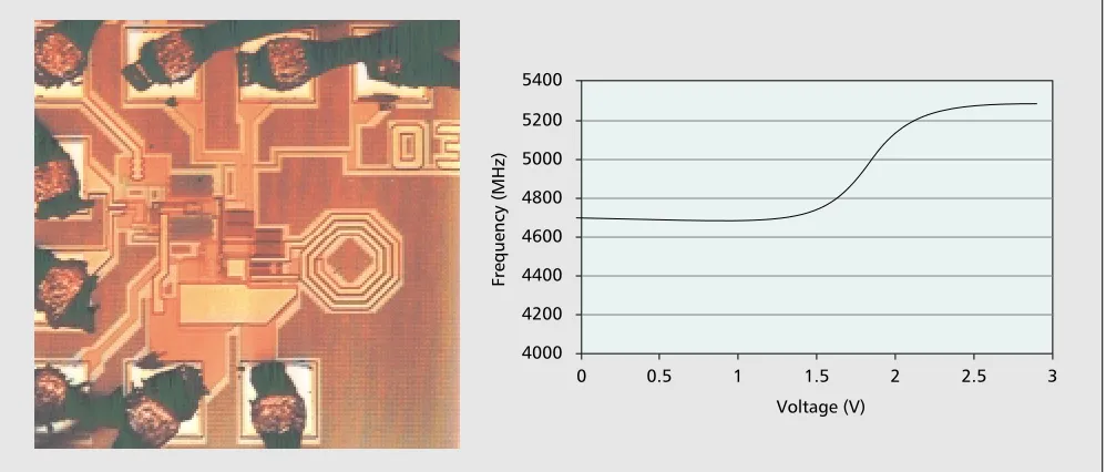
For the VCO we use the negative transconductance princi-ple in order to get a high oscillation swing. Compared to the Colpitts oscillator topology we used earlier, we achieve a slightly better phase noise figure of –105 dBc/Hz at 1 MHz offset. The VCO operates down to below 2 V supply with a tuning range of about 550 MHz at nominal conditions. At 2.5 V, the power consumption is 15 mW. The area is 0.6 ×0.5
µm2. As an example of our circuits, Fig. 5 shows the chip photo of the VCO discussed above together with its measured tuning range.
Our second VCO operates at 810 MHz with an external tank. Combined with our polyphase filter and two mixers, this essential circuit block of the receiver retrieves the I and Q components from the IF signal. One mixer realizes 12 dB of conversion gain and achieves the 1 dB compression point (CP1dB) at +1 dBm while consuming 12.5 mW power. The
"Figure 5.A chip photo of a VCO (left) and measured tuning range (right).
0.5
Frequency (MHz)
Voltage (V) 4200
4400 4600 4800 5000 5200 5400
4000
1 1.5 2 2.5 3
active chip area of the entire IF downconverter is about 0.7 ×
0.7 µm2with a power consumption of about 25 mW.
SPW Model of Baseband with Synchronization
The complete baseband processor, consisting of the data path of transmitter and receiver as well as the synchronization, has been modeled using the Signal Processing Worksystem (SPW) from Cadence™. This SPW model represents the basis for our hardware implementation. The total effort for modeling the baseband processor in SPW was approximately two man years. In this section some aspects of synchronization are discussed in more detail.In the IEEE 802.11a and Hiperlan/2 standard preamble symbols are defined that have to be transmitted at the begin-ning of each frame. This makes the synchronization procedure completely different from that used for continuous transmis-sion (i.e., DAB, DVB).
A so-called one-shotsynchronization has to be used, where a first estimation of the synchronization parameters is obtained using some preamble symbols. These parameters are kept constant throughout reception of a frame. The estimator is mainly based on autocorrelations and crosscorrelations, and the preamble structure has to be optimized in order to mini-mize the estimation variance. Since IEEE 802.11a is only directed at LAN applications, it defines only a single pream-ble structure. In the case of Hiperlan/2, four preampream-bles were proposed.
It is obvious that the one-shot synchronization is not opti-mal in terms of performance because it considers constant parameters during the frame reception. Nonetheless, due to the timing constraints this is the only solution when transmit-ting at high bit rates. In the following, we discuss the three most important parameters to be synchronized: symbol/frame
timing offset, carrier frequency offset, and sampling clock fre-quency offset[5].
•Symbol/frame timing offset: When receiving a frame, it is nec-essary to establish the timing for the frame (i.e., to determine its first sample). Any mismatch in the determination of this parameter will introduce a phase error, which will depend on the subchannel position but be constant from symbol to sym-bol (DFT property: delay in time turns into a linear phase in frequency). Furthermore, if the symbols are affected by a dispersive channel, some of the information from one sym-bol will spread out into the next symsym-bol. In this case, if the initial position found for that symbol falls in the region affected by this spreading, the timing offset will also intro-duce some intersymbol interference (ISI).
•Carrier frequency offset: The carrier frequency offset is due to some frequency mismatch during RF downconversion. The main effect is the loss of orthogonality in the received signal because we no longer have an integer number of periods for each of the transmitted subcarriers inside the symbol time (FFT time), thus producing intercarrier interference (ICI). •Sampling clock frequency offset: The sampling clock
fre-quency offset denotes the frefre-quency mismatch between the clock at the transmitter and the one at the A/D converter in the receiver. Due to thermal drift, this frequency offset will also change (slowly) in time. Although its effect is quite small for BPSK and QPSK, sampling clock frequency offsets could have a serious effect when transmitting in 64-QAM mode.
The way to estimate all these parameters depends on the preamble structure being used. The order in which the param-eters will be estimated is also a crucial question.
In our solution, shown in Fig. 6 and discussed in [6], the whole estimation process is divided into two parts: time and
"Figure 6.A scheme of synchronization and channel estimation blocks for the IEEE 802.11a Standard (no sampling clock frequency
correction included). ~
Outer receiver
Pilot and null channels extraction
Cyclic prefix extraction FFT
ADC
SPSt + LPSt
SPSf LPSf
pa
pt
2 y(n)
Time domain synchronization (with NCO for α
correction)
Frequency domain synchronization
(with FFT and β correction)
α+ β
β α Decimator
S / P 1-D Wiener filter
(time direction) SNR
First sample out
Pilot information
2x48 2x48
2x48 2x48 2x64 2x64 2x80
2x4
Time correction
Frequency correction
Channel correction
Global timing
Channel statistics
Pilot generator
1-D Wiener filter (frequency direction)
NCO
(Reference channel estimation)
SNR estimation
frequency domain. The time domain processing is basically an autocorrelationoperation on the input signal and serves to detect the symbol tim-ing as well as to obtain an initial estimation for the frequency offset (fractional frequency offset). The subsequent frequency domain processing uses a crosscorrelator to obtain the integer part of the frequency offset. During the frequency domain processing we also obtain a first estima-tion of the channel characteristics.
The problem of estimating the sampling clock frequency offset is more complex. We use a fixed
clock and an interpolator filter placed at the output of the A/D converter with an interpolation factor that depends on some error signal. Afterward, a decimator filter is deployed to comply with the 20 MHz sampling frequency. Possible struc-tures for the interpolator are explained in [7], where the authors derive a method to generate the error signal for the interpolator by using the pilot information.
•Channel estimation: Both standards define a pilot-based sym-bol structure [1, 2], which means that the information trans-mitted in some of the subchannels is known a priori at the receiver. We can make use of these pilots in the channel esti-mator. In particular, when using pilot channels we are mak-ing an attempt to sample the channel, simplifymak-ing the problem to a linear interpolation problem. This method works if the pilot spacing is small compared to the coherence bandwidth of the fading channel.
However, in the IEEE 802.11a and Hiperlan2 standards the pilot spacing is not small enough. Thus, a different solution had to be found. A Gaussian interpolator or some architecture based on Lagrange interpolators has been proposed [8]. Other possibilities are Wiener filtering or the method of least squares. The solution we have adopted is based on Wiener filtering with some simplification of the channel statistics. In a strict sense, the Wiener filtering should be two-dimensional. However, due to the nearly independent behavior of the correlation functions in time and frequency, the problem is simplified by using two one-dimensional filters [9].
Whatever method is used, it will only work if the channel impulse response (CIR) is shorter than the cyclic prefix. If not, some ISI (modeled as noise) will degrade the channel estimations. To avoid this, for certain applications a preequal-izer filter must be used to shorten the CIR.
Hardware Implementation of the
FFT Processor and Viterbi Decoder
FFT Processor— As discussed in previous sections, the FFT/IFFT is an integral component of the PHY layer of OFDM-based communication systems.
According to the specifications of IEEE 802.11a and Hiperlan/2, the OFDM transceiver has to perform a 64-point IFFT (in the transmit direction) or FFT (in the receive direc-tion) within 3.2 µs. This implies that a highly specialized archi-tecture has to be used to satisfy this tight timing constraint. Also, from a power dissipation point of view an implementa-tion using dedicated hardware is beneficial when compared with a general-purpose DSP architecture.
It is possible to use the conventional Cooley-Tukey algo-rithm [10] for this purpose, but to meet the timing specifica-tion one has to employ a highly parallel structure or use a very high frequency of operation that leads to high area and power consumption. Thus, it is necessary to develop a simple but efficient design methodology that on one hand keeps the area and power consumption as low as possible and on the other hand satisfies the timing constraint.
In our algorithmic formulation, we reformulate the 64-point FFT in terms of a 2D 8-64-point FFT. The 64-64-point FFT can be computed by first performing an 8-point FFT of the appropriate input data slot, then multiplying them with nine unique interdimensional constants and finally once again generating an 8-point FFT of the resultant data. The IFFT is performed by first swapping the real and imaginary parts of the incoming data and then performing the for-ward FFT on them and once again swapping the real and imaginary parts of the data at the output. This method allows us to perform the IFFT without changing any inter-nal coefficients and thus results in a more efficient hard-ware implementation.
From the algorithmic point of view, our method requires fewer arithmetic computations than that of the conventional Cooley-Tukey algorithm. The Cooley-Tukey algorithm requires 192 complex multiplications and 1152 additions/sub-tractions. Our algorithm needs only 49 complex multiplica-tions and 994 addimultiplica-tions/subtracmultiplica-tions, that is, our method requires only 25 percent of the real multiplications and 86 percent of the additions/subtractions of the conventional approach. This results in a significant reduction of power dis-sipation and enables high-speed operation.
The basic block diagram of the proposed 64-point FFT/IFFT module is shown in Fig. 7. It uses a novel archi-tecture consisting of one input buffer, one 8-point FFT mod-ule, an internal buffer and four real multipliers. The input data slots are stored in the buffer every 4 µs and the 8-point FFT module fetches the data from the buffer as soon as the computation of 64-point FFT for a particular data slot is completed. The multiplied data are stored in an internal reg-ister, cb (shown in Fig. 7), from where they are rerouted to the 8-point FFT module in appropriate order to generate the final result. The final results are stored in the buffer cb once again from where the output is generated in a word-serial manner. The input mechanism, the internal computa-tion process, and the data output mechanism are carried out in pipelined fashion. The parallelism and pipelining intro-duced in this architecture are also favorable from a power consumption point of view.
The architecture is synthesized for 0.25 µm CMOS tech-nology operating at 20 MHz clock frequency. The simulation results for the synthesized circuit demonstrates the correctness of the structure. The silicon area of the complete FFT core is 5.5 mm2, which is equivalent to 81K gates in that technology. At the operating frequency of 20 MHz the average power consumption of the whole structure is 67 mW. Clock gating is deployed to reduce the total switched capacitance.
At 20 MHz clock frequency the core architecture is capa-ble of computing a 64-point FFT/IFFT in 0.9 µs. However, with the serial input and serial output circuitry, the through-put of the architecture is one 64-point FFT/IFFT at every 3.15
µs. These figures indicate that the proposed architecture is highly suitable for application in OFDM based wireless broad-band communication systems.
"Figure 7.The basic architecture of the FFT/IFFT processor.
Buffer
(cb) O/P
Mux 8-point
FFT Mux
Multiplier unit Input
The layout of the architecture is done for IHP’s in-house 0.25 µm CMOS technology. Currently, the FFT processor is being fabricated in-house as a discrete component.
Viterbi Decoder— A 6-bit soft-decision Viterbi decoder has been designed and implemented. It consists of an add-compare-select unit which is instantiated 64 times, a memory that stores the decision of 64 nodes, an algorithm that searches for the minimum of the Hamming distance, as well as a traceback unit. The Viterbi decoder was implemented using a standard ASIC design flow and fabricated in UMC’s 0.25 micron 5 metal layer CMOS technology. A die photo of the chip is pre-sented in Fig. 8. The chip has the following parameters: The area is 9 mm2(137 k gates), the clock frequency is 80 MHz and the worst case power consumption is 625 mW. To our knowledge there is currently no discrete device available which fulfills this specification.
DLC Implementation
The abstract SDL simulation model for IEEE 802.11 is com-pleted. It implements the full DLC functionality as defined in this standard and serves as a basis for a real-time implementa-tion. We are now working on the implementation of the 802.11 MAC on a 33 MHz NET+ARM™ processor board with hardware accelerators. For a version implementing the station’s functionality only, the C source code generated auto-matically from the SDL model consists of about 35,000 lines of code corresponding to a text size of 1.1 Mbytes. The exe-cutable ROM image for the ARM7TDMI processor consists of about 350 kbytes user code generated from SDL plus 650 kbytes for pSOS. The required resources will increase when the functionality is extended, for example, by that of an access point. The total effort for implementing the abstract SDL model including a comprehensive test environment and docu-mentation amounts to approximately 3 man years.
For Hiperlan/2, the abstract SDL simulation model is cur-rently under development.
Conclusions
Currently, there are many institutions working on implementing modems according to the Hiperlan/2 and IEEE 802.11a stan-dards. The computational requirement for the baseband
function-ality is very high. In particular, the response time for generating acknowledgment frames requires extremely small latency in the baseband processing. Therefore, for the digital baseband block a pure hardware implementation, with some opportunity for system configuration using embedded FPGA, is advocated. This also results in comparatively low power dissipation.
The DLC is being implemented on a standard processor with some hardware accelerators attached. In particular, the CRC, the encryption/decryption unit, and timer functions will be mapped onto dedicated hardware.
In order to reduce total system cost, a single chip modem comprising analog front-end, D/A and A/D converters, base-band processor, and DLC processor is being developed. The single-chip solution is also expected to be superior in terms of performance and power dissipation when compared to multi-chip implementations. A token-flow approach was used to decentralize the control functions. This allows for easy appli-cation of clock gating techniques to further minimize the sys-tem power dissipation. Further work will apply asynchronous circuit techniques for connecting modules across the chip.
The single-chip wireless broadband modem is part of an initiative for a truly single-chip PDA that additionally consists of an application engine, a protocol processor, and a power management and test engine. These components are currently under development and will form the basis of a versatile sys-tem components library. We strongly believe in a multiproces-sor on chip approach where each procesmultiproces-sor can be optimized according to its functional requirements. The hardware- soft-ware partitioning influences the trade-off between system flex-ibility and power efficiency. Therefore this decision requires good understanding of the specification and the interaction between system components. We are still at the beginning of understanding system considerations under these overall opti-mization criteria.
References
[1] ETSI DTS/BRAN 030003-1, “Broadband Radio Access Networks (BRAN); HIPERLAN Type 2 Functional Specifications. Part 1 — Physical (PHY) layer”; June 1999.
[2] IEEE P802.11a/D7.0, “Part 11: Wireless LAN Medium Access Control (MAC) and Physical Layer (PHY) specifications: High Speed Physical Layer in the 5 GHz Band,” July 1999.
[3] AMD: Pcnet™-Mobile Solution, http://www.amd.com/products/npd/ overview/20192.html
[4] Intersil: PRISM” II WLAN Chip Set, http://www.intersil.com/prism/ser-pii-11mbps.asp
[5] Michael Speth et al., “Optimum Receiver Design for Wireless Broad-Band Systems Using OFDM - Part I,” IEEE Trans. Commun., vol. 47, no. 11, Nov. 1999, pp. 1668–77.
[6] B. Stantchev and G. Fettweis, “Burst Synchronization for OFDM-Based Cellular Systems with Separate Signaling Channel,” VTC ‘98, Ottawa, Canada, pp. 758–62.
[7] F. M. Gardner, “Interpolation in Digital Modems – Part I: Fundamen-tals,” IEEE Trans. Commun., vol. 41, no. 3, Mar. 1993, pp. 501–7. [8] J. Kyoung Moon, S. I. Choi, “Performance of Channel Estimation
Meth-ods for OFDM Systems in a Multipath Fading Channel,” IEEE Trans. Cons. Elec., vol. 46, no. 1, Feb. 2000, pp. 161–70.
[9] S. Kaiser, “Multi-Carrier CDMA Mobile Radio Systems – Analysis and Optimization of Detection, Decoding and Channel Estimation,” Reihe 10, no. 531, 1998 VDI Verlag.
[10] J. W. Cooley and J. W. Tukey, “An Algorithm for the Machine Calculation of Complex Fourier Series,” Math. Comp., vol. 19, 1965, pp. 297–301.
Additional Readings
[1] A. Troya, G. Lippert and B. Stantchev, “Simulation Aspects of an OFDM-based Physical Layer of Wireless Broadband Networks,” Proc. 5th Int’l. OFDM-Wksp., Hamburg, Germany, Sept. 12–13, 2000.
Biographies
ECKHARDGRASS([email protected]) received his Dr.-Ing. degree in electronics from the Humboldt University Berlin in 1992 . He worked as a visiting research fellow at Loughborough University, United
Kingdom, from 1993 to 1995 and as a senior lecturer in microelectronics at the University of Westminster, London, from 1995 to 1999. Since 1999 he works at the IHP-GmbH, leading a project on the implementation of a wire-less broadband communication system. His research interests include data-driven (asynchronous) signal processing structures and low-power VLSI implementation of communication systems.
KLAUSTITTELBACH-HELMRICH([email protected]) received his diploma degree in physics from Humboldt University, Berlin, Germany, in 1984. He worked at the Institute for Semiconductor Physics, Frankfurt (Oder), Germany, in the field of experimental semiconductor physics until 1995. Now he works in Systems Department of the IHP, Frankfurt (Oder), Germany. His research interests include protocol and hardware design for broadband wireless communication systems.
ULRICHJAGDHOLD([email protected]) received his diploma in physics (M.Sc.) from Dresden Technical University in 1987. From 1987 to 1996 he worked at the technology integration group of the Institute of Semiconductor Physics (IHP) in Frankfurt (Oder) on CMOS, BiCMOS, and SiGe technologies and device physics. Since 1997 he has worked in the Sys-tems Department of the IHP on 5 GHz WLAN projects like IEEE 802.11a and Hiperlan/2 focusing on baseband integration issues.
ALFONSOTROYA([email protected]) received his M.Sc. degree in telecommunication engineering from the Polytechnical University of Catalonia (UPC), Barcelona, Spain, in 1999. The same year he joined the IHP GmbH, where he is currently working toward a Ph.D. degree. His main research interests are OFDM and the design and implementation of algorithms for synchronization and channel equalization in wireless communications.
GUNTHERLIPPERT([email protected]) received his diploma in physics (M.Sc.) from the Technical University of Chemnitz in 1982 and his Ph.D. from the University of the Federal Armed Forces Munich in 1995. Since 1982 he has worked at the IHP Frankfurt (Oder), Germany. Until 1997 he was mainly involved in material research for CMOS and SiGe technology development. Now he works in the Systems Department on the VLSI imple-mentation of an OFDM baseband processor.
OLAFKRÜGER([email protected]) received his diploma degree in chemistry in 1988 and a Ph.D. degree in physical chemistry in 1993, both from Humboldt University, Berlin, Germany. From 1995 to 1997 he was a postdoctoral fellow at the California Institute of Technology (Pasadena, CA). In 1997 he joined the IHP. Since 1999 he has been working in the Systems Department on protocol development for wireless broad-band communication.
JENSLEHMANN([email protected]) received his diploma in telecommunications from the University for Engineering and Business, Berlin, Germany in 1999. In 1999 he joined the IHP, where he has been involved in R&D of wireless broadband communication systems. He works on the design and implementation of protocol hardware and software.
KOUSHIKMAHARATNA([email protected]) received his B.Sc. degree in physics and M.Sc. degree in electronic science from Calcutta University in 1993 and 1995, respectively. He completed his Ph.D. work in February 2000 from Jadavpur University, Calcutta, India. Since then he has been working as a postdoctoral fellow in IHP. His research interests include the development of VLSI architectures for application in DSP and communi-cations, computer arithmetic, and low-power circuit design.
KAIF. DOMBROWSKI([email protected]) received his M.Sc. degree in physics at the University of Freiburg, Germany, in 1996 and his Ph.D. in physics at the Technical University of Cottbus, Germany, in 2000. His research areas since 2000 include profiling and power optimization of wireless protocols.
NORBERTFIEBIG([email protected]) received his M. Sc. degree in electronics from the University of Technology Dresden in 1982. Between 1982 and 1990 he worked as a design engineer and team leader in the design of integrated circuits for logic families and computer periphery. After working in the consumer products field with Thomson Multimedia he joined its R&D lab in 1993, where he worked on analog integrated circuits for digital audio and video broadcasting (DAB & DVB). Since 1997 he is leading a team working on integrated transceiver front-ends for wireless applications in the 5 GHz range with the IHP in Frankfurt (Oder).
ROLFKRAEMER[M] ([email protected]) received his diploma and Dr.-Ing. degrees from the computer science department of the RWTH-Aachen, Germany. He has worked for 15 years in R&D of communication and multimedia systems at Philips-Research in Hamburg and Aachen. Since 1998 he is professor of systems at the IHP in Frankfurt and TU-Cottbus. He leads the systems research department of the IHP where his research focus is on wireless Internet systems from application to systems on chip. He is co-founder of the startup-company lesswire AG where he holds the posi-tion of the CTO. He is member of the IEEE Computer Society, the VDE-NTG, and the German Informatics Society.