Abstract— Design considerations are reported for assistive human arm recovery procedures by using a prototype of an exoskeleton for wrist and elbow joints. The design and operation of the exoskeleton arm are revised to achieve a fairly simple use in recovery procedures for disable people in kinetotherapy actions. Results show a suitable exoskeleton arm behavior and proper motion properties in lab tests with exoskeleton programming that have been performed in accordance with specific human arm recovery procedures.
Index Terms— Experimental robotics, arm recovery, kinematics, exoskeleton
I. INTRODUCTION
OWADAYS many exoskeletons and robotic systems constructive solution types have been designed by taking into account the human activities in different domains, but also human specific recovery procedures [1], [2], [3], [7]-[10]. These were designed for human arms motions and for human locomotion system recovery and rehabilitation.
As regarding the human arms specific motions, it can be found different types of robotic systems used in human upper limb functional recovery. A significant exoskeleton design is the one called WOTAS and was elaborated by a group of researchers, lead under J. Rocon and J.L. Pons (Spain) which solve a problem for the patients who cannot take medication by themselves. This exoskeleton has three degrees of freedom which correspond with the elbow flexion/extension, pronation/supination and wrist flexion/extension [12]. In case of physiotherapy recovery programs another exoskeleton called ARMin II was designed by T. Nef, M. Mihelj, G. Colombo, R. Riener. This has 6 DOF and enables pronation/supination and flexion/extension motion at the wrist level [14]. Other robotic systems which have as a main application the human upper limb kinetotherapy recovery programs are shown in
Manuscript received March 23, 2017, Revised April 13, 2017
S. Dumitru is with Faculty of Computers and Automation, University of Craiova. Decebal street no. 107. Romania (e-mail:
A. S. Rosca is with the Faculty of Mechanics, University of Craiova. Calea Bucuresti street no. 107. Romania (corresponding author to provide phone: +04 0251543739; e-mail: [email protected]).
L. Ciurezu is with the Faculty of Mechanics, University of Craiova. Calea Bucuresti street no. 107. Romania (corresponding author to provide phone: +04 0251543739; e-mail: [email protected] ).
A. Didu is with the Faculty of Mechanics, University of Craiova. Calea Bucuresti street no. 107. Romania (corresponding author to provide phone: +04 0251543739; e-mail: [email protected] ).
[13], [15] and [16].
By taking into account the state-of the-art in case of human upper arms exoskeletons designed for specific kinetotherapy recovery programs, in the University of Craiova - Faculty of Mechanics research frame, a group of researchers under the lead of PhD. Eng. Dumitru N., have developed an exoskeleton prototype used for human upper limb therapeutic programs implementation as in [8].
Thus the paper research core focuses on the design of this exoskeleton prototype from constructive viewpoints and these are represented through three major sections. First research section refers to the exoskeleton mechanical components design and manufacturing operations. Second section will be allocated for command and control operations. Third section of the research core regards the human arm exoskeleton functionality by performing experimental tests with specific evaluation equipment, namely SIMI Motion.
II. HUMANUPPERARMEXOSKELETON The proposed exoskeleton was designed for elbow and wrist joints recovery procedures of a human upper limb. By taking into account the literature data which regards the human upper limb mobility, the mentioned joints were analyzed by specialists with different equipments and devices. They obtained angular amplitudes for the considered joints like the research from [7]. Thus, the proposed exoskeleton joints will have to respect the limits presented in Table I.
TABLEI
HUMAN UPPER LIMB JOINTS ANGULAR AMPLITUDES
Joint Motions Angular variations (degrees)
Angular amplitude
(degrees) Wrist
Flexion/Extension 85° – 0 - 75° 155°- 160° Radial/Ulnar
Deviation 20° – 0 – 35° 50°- 55° Elbow Pronation/Supination 90° – 0 - 70° 150°- 160°
Flexion/Extension 0- 142° 135°- 142°
By considering the mentioned values, the human upper limb exoskeleton structure has 3 mobility joints. These will assure wrist flexion/extension, radial/ulnar deviation and elbow pronation/supination motions. Moreover this consists in 3 servomotors for the proposed human joints functional recovery and a command&control electronic platform with an user-friendly interface and easy operation features. The exoskeleton mechanical parts are shown in Fig.1 and Fig. 2. This has on its structure two conic gears (A, B) and a cylindrical one (C).
Design Considerations of a Human Arm
Exoskeleton
Dumitru S., Rosca A. S., Ciurezu L. and Didu A.
Fig. 1. Human upper arm exoskeleton virtual model.
Fig. 2. Human upper arm exoskeleton virtual model (exploded view).
The exoskeleton components were manufactured from aluminum alloys and the desired torques developed by servo-motors transmitted through two conic gears and one cylindrical gear to the exoskeleton components. These gears are manufactured from plastic material type PVC-C, through virtual prototyping procedures.
Thus, these gears were manufactured based on LOM technology as it can be remarked in [18],by using a special 3D printer type SD 300 provided by Solido Company. The principle is schematized in Fig. 3.
A cylindrical gear is presented in Fig. 4 and also it can be remarked the rough model of this.
The LOM technology assures the components manufacturing processes based on thin plastic layers sticking and cutting operations with the aid of a laser beam.
Basically, after the manufacturing processes the obtained models do not require any additional adjustments or corrections. These were inserted directly onto exoskeleton prototype structure.
[image:2.595.57.287.62.244.2]The obtained exoskeleton prototype is shown in Fig. 5.
Fig. 3. LOM technology principle according with [18].
Fig. 4. SOLIDO 3D printer and an exoskeleton cylindrical gear prototype.
A
B
C A
C
[image:2.595.46.290.274.463.2] [image:2.595.305.549.285.763.2]Fig. 5. Human upper arm exoskeleton prototype.
This prototype was manufactured by having in sight a lot of theoretical studies under kinematic and dynamic aspects as the ones presented on [4].
III. EXOSKELETON COMMAND AND CONTROL
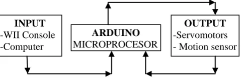
The proposed human arm exoskeleton command&control platform was especially designed in order to assure a proper functionality for each servomotor, but also through several combinations of these by putting together the programming sequences. These sequences were created in accordance with the special motions and procedures recommended by a kinetotherapy specialist. The designed platform has on its main structure an ARDUINO Duemilanove board. The platform can command and control the units in three modes: - one mode through a computer with the specific ARDUINO program via on USB interface;
- second mode by uploading the program on the ARDUINO Board storage capacity and actuating the exoskeleton independently, without a computer, just plug&play to any 5Volts CC electrical source;
- third mode with the aid of a WII mobile console, which was modified especially for this exoskeleton prototype.
The ARDUINO Board has the functionality logic scheme presented in Fig. 6.
Fig. 6. ARDUINO Board scheme for the human upper arm exoskeleton prototype.
The most complex programming mode is the third one, namely the one with the use of a WII Console. This console has inside a 3 axis accelerometer type MMA7260QT. Thus, the servomotors will receive position data processed by the ARDUINO Board in accordance with the WII Console position. During the tests it was assumed that the WII Console will be manipulated by a kinetotherapy specialist during specific recovery procedures. In Fig. 7 it is represented a monitoring diagram of the WII accelerometer
signals obtained with proper software in real time.
Also the WII Console has two buttons which can be configurable through source codes of ARDUINO program, which if these are simultaneously pressed, a “freeze” sequence will be activated and the exoskeleton will pass on emergency mode for patient protection in order to unarm the upper limb joints.
[image:3.595.306.550.296.443.2]In case of the second mode the specific kinetotherapy procedure transferred to ARDUINO program remains as a resident code in EEPROM memory of this board. For erasing this it is necessary to press the RESET button located on the ARDUINO board. The command&control servomotors power source will be assured from the ARDUINO board at a value of 5 Volts. Also this will have an external socket for power supply from an external electricity source of 5 Volts. The program can be periodically updated by a specialist and this can be rewritten on each time if necessary.
Fig. 7. WII Console accelerometer response signals during manipulation.
The electronic circuit has also a micro switch and an electric protection component in case of overcharging the system.
The chosen servomotors develop a torque of 1.3Newton·meter and these were connected to ARDUINO board trough connectors type RJ-11.
An aspect which regards the acceleration components values configuration is shown in Fig. 8.
Fig. 8. Configuration parameters for the console accelerometer manipulation.
INPUT
-WII Console -Computer
ARDUINO
MICROPROCESOR
OUTPUT
[image:3.595.50.291.560.638.2] [image:3.595.311.540.597.748.2]The obtained data during experimental tests of the exoskeleton prototype can be automatically recorded in the “PROCESSING” ARDUINO software, where these can be seen and also modified in accordance with the program proper codes. These data can be also exported in an output files under *.txt format. Based on the used technology for the exoskeleton programming&control, it can be mentioned that the outputs values are essential to the kinetotherapy specialist. These can highlight the evolution of the patient recovery procedures in real-time, but also during a period of exercises.
IV. EXOSKELETON EXPERIMENTAL ANALYSIS
The exoskeleton prototype experimental analysis was performed with the aid of SIMI Motion equipment in order to validate the real model. The aim of this analysis was to obtain the angular amplitudes of the equivalent joints which the prototype was designed and compared with the ones existent in the literature data [4].
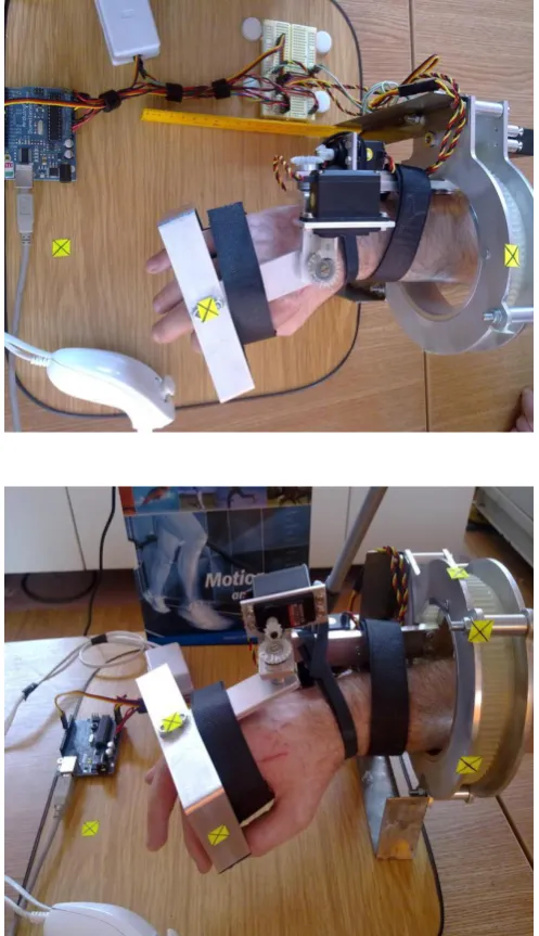
[image:4.595.304.547.184.372.2]The experimental analysis consists on attaching a set of markers with reflexive properties on some exoskeleton characteristic points. This can be remarked in Fig. 9.
Fig. 9. Markers attachment on the human upper arm exoskeleton prototype.
Some screenshots during these experimental tests are represented in Figs. 10 and 11. In Fig. 11 is shown the auto generated stick obtained in the SIMI software environment [17].
In this way, the exoskeleton prototype was analyzed by taking into account a real human upper limb.
[image:4.595.45.294.346.778.2]The experimental analysis was developed for each joint motion separately and for a single motion cycle. Thus, there were performed 4 experimental tests.
Fig. 10. Screenshot during exoskeleton wrist flexion/extension.
Fig. 10. Screenshot during exoskeleton elbow pronation/supination.
The obtained results after the experimental tests were represented trough diagrams, these are shown in Figs. 12, 13 and 14.
[image:4.595.304.547.409.615.2]Fig. 11. Generating the equivalent stick for wrist flexion/extension activity with the aid of SIMI Motion software.
Fig. 12. Exoskeleton prototype wrist flexion/extension angular variation [degrees] vs. time [sec].
Fig. 13. Exoskeleton prototype wrist radial/ulnar deviation angular variation [degrees] vs. time [sec].
Also the angular motion law obtained from this activity (Fig. 12) has a curvature with a few spikes and this occurs due to the contact between conic gears teeth. In reality these spikes cannot be seen by a human operator with his own eyes, because SIMI Motion equipment analyzes these with a 500 frames/second speed. The same remark remains also for other results presented in Fig. 13 and Fig. 14.
Fig. 14. Exoskeleton prototype elbow pronation/supination angular variation [degrees] vs. time [sec].
By analyzing the wrist ulnar/radial deviation from Fig. 13, the obtained angular amplitude has a value of 51.51 degrees, and respects the limit specified in Table I. Also on this figure it can be observed that the time period, in which the experimental test occurs, is different than the ones from other cases. This comes from conic gear ratio which is smaller than ones from other gear pairs. The difference in case of time period is one second, almost imperceptible for the exoskeleton prototype and also for the kinetotherpay specialist.
The elbow pronation/supination activity was developed with an angular variation from -66.13 degrees to + 90.81 degrees according with the graph from Fig. 14. Thus, it results angular amplitude of 156.13 degrees and this is situated at the limit specified in Table I for this type of activity.
[image:5.595.310.547.142.346.2] [image:5.595.51.289.303.506.2] [image:5.595.50.290.548.746.2]V. CONCLUSIONS
Through this research it was obtained an exoskeleton especially designed for human upper limb recovery through specific kinetotherapy procedures. This exoskeleton prototype can be successfully used on the following tasks:
- muscular forces recovery and increasing the muscular tonus;
- increasing and adapting the effort capacity;
- increasing the human upper limb articulations mobility; - improving the coordinating and control functions of the human upper limb.
Thus the exoskeleton prototype configuration demonstrate the optimal functionality of this by inserting in the mechanical structure two pairs of conic gears and one pair of cylindrical gear, actuated with the aid of three servomotors.
The obtained exoskeleton prototype was designed in a compact form, in such manner that it can be placed on a mobile wheelchair and from this viewpoint it can be considered a mobile one and depends only from a 5Volts CC power supply source.
Also this was designed in a parameterized mode and it can be adapted for any human subject anthropometric dimensions (especially adults and elderly persons). This can be used for both upper limbs due to the flexibility of the components (left or right hand).
REFERENCES
[1] N. Dumitru, C. Copilusi M. Ciortan, „Kinematic and Dynamic Study Contributions on Human Jaw System”. Medical and Service Robotics
Workshop - Lausanne. Ed. Springer. 8 pages. 2014.
[2] N. Dumitru, C. Copilusi, D. Tarnita, S. Dumitrache, ”Dynamic Analysis of an Exoskeleton New Ankle Joint Mechanism” New Trends in Mechanism and Machine Science Mechanisms and
Machine Science Volume 24. Springer International Publishing,
2014. pp 709-717.
[3] N. Dumitru, R. Malciu and V. Grecu, “Theoretical and experimental study of the human upper limb dynamic behavior”, Proceedings of 2011 2nd International Conference on Mechanical Engineering,
Robotics and Aerospace, (ICMERA 2011), 2011. pp. 151-156.
[4] Freivalds A. “Biomechanics of the upper limbs”. 2004. CRC Press.
[5] I. Geonea, M. Ceccarelli, G. Carbone, “Design and Analysis of an Exoskeleton for People with Motor Disabilities”, 14th World
Congress in Mechanism and Machine Science. 2015. Taiwan.
[6] I. Geonea, C. Alexandru, A. Margine, A. Ungureanu, “Design and Simulation of a Single DOF Human-Like Leg Mechanism”, Applied
Mechanics and Materials Journal Vol. 332, 2013, pp. 491-496,
doi:10.4028/www.scientific.net/AMM.332.491.
[7] I. Geonea, A. Ungureanu, N. Dumitru, L. Racila, “Dynamic Modelling of a Four Legged Robot”, New Trends in Mechanism and
Machine Science Mechanisms and Machine Science. Volume 24,
Springer International Publishing, 2014. pp 147-155.
[8] V. Grecu, N. Dumitru, C. Copilusi, "Human Upper Limb Robotic System Experimental Analysis by Using CONTEMPLAS Motion Software", Applied Mechanics and Materials Journal, Vols. 325-326, 2013. pp. 1062-1066.
[9] R. Gopura, R.C. Arachchilage, K. Kazuo, “EMG-Based Control of an Exoskeleton Robot for Human Forearm”, IEEE International
Conference on Robotics and Automation, USA. 2008.
[10] K. Kiguchi, T. Takakazu, F. Toshio, “Neuro-Fuzzy Control of a Robotic Exoskeleton With EMG Signals”. IEEE Transactions on
Fuzzy Systems. 2004.
[11] K. Kiguchi, F.Toshio, “A 3 DOF Exoskeleton for Upper Limb Motion Assist: Consideration of the Effect of Bi-articular Muscles”. The 2004
IEEE International Conference on Robotics and Automation. ICRA-
2004.
[12] J.C. Moreno, E. Rocon, A. Ruiz, F. Brunetti, J. L. Pons, “Design and implementation of an inertial measurement unit for control of artificial
limbs: application on leg orthoses”. IEEE 18th International
Conference on Micro Electro Mechanical Systems MEMS- 2006.
[13] J.C. Perry, “Design and development of a 7 degree-of-freedom
powered exoskeleton for the upper limb”. PhD Dissertation,
University of Washington (2006).
[14] T. Nef, M. Mihelj, G. Colombo, R. Riener, “ARMin – Robot for rehabilitation of the upper extremities”. IEEE Conference on
Robotics and Automation, ICRA. 2006.
[15] N.G. Tsagarakis, D.G. Caldwell, “Development and control of a physiotherapy and training exercise facility for the upper limb using soft actuators”. Proceedings of IEEE International Conference on
Advanced Robotics, Portugal (2003).
[16] N.G. Tsagarakis, D.G. Caldwell, “Development and control of a soft-actuated exoskeleton for use in physiotherapy and training”. Journal
of Autonomous Robots, Special Issue on Rehabilitation Robotic. 2003.
[17] SIMI Motion Analysis Technical data Manual. 2010.
[18] B. Khan, Rapid Prototyping – Laminated Object Manufacturing. [Online}. Available at:
![Fig. 3. LOM technology principle according with [18].](https://thumb-us.123doks.com/thumbv2/123dok_us/418664.539428/2.595.305.549.285.763/fig-lom-technology-principle-according.webp)
![Fig. 14. Exoskeleton prototype elbow pronation/supination angular variation [degrees] vs](https://thumb-us.123doks.com/thumbv2/123dok_us/418664.539428/5.595.310.547.142.346/exoskeleton-prototype-elbow-pronation-supination-angular-variation-degrees.webp)