Abstract—We have developed a fundamentally new design of adaptive suspension systems of vehicles. Their technical characteristics and functional abilities are far better than the existing designs of suspensions. We have developed the following main suspension components of vehicles: a lockable adaptive shock absorber with an ultra-wide range of control performance, implementing "lockout" mode by means of blocking adaptive shock absorber, and an elastic element with progressive non-linear characteristic and automatic optimization of localization of work areas. Our patents confirm the novelty and efficiency of our major design decisions.
Advantages of our developments in the vehicle suspensions are the following. Firstly, it should be noted that when the vehicle is in a wide range of speeds in a so-called "comfort zone", we were able, by applying the non-linear elastic element, to reduce significantly the stiffness of the elastic suspension elements in compare with the regular structures - at least in two times. Dynamic loads on the crew, passengers, equipment, components and assemblies of the vehicles are reduced in a great extent. Secondly, the stiffness of the non-linear elastic element beyond "comfort zone" is increasing dramatically: first - more than three times in comparison with regular elastic elements; and further increasing of the stiffness of the elastic elements is more than 60 times.
In case of usage of the developed designs of the lockable adaptive shock absorbers and the nonlinear elastic elements, the vehicles will be equipped with the suspensions, whose techno-economic indicators surpass in a qualitative sense the world-famous counterparts.
Index Terms— Adaptive suspension, characteristics, design, vehicle
I. INTRODUCTION
T is well known fact that, while designers create a suspension system of a vehicle, they always have to solve the problem of reconciling of two groups of conflicting requirements [1]:
1. Requirements to ensure a given level of smoothness, rapidity, minimize dynamic loads acting on the cargo, nodes, passengers and drivers of the vehicle;
2. Requirements of manageability, security, stability, stabilization of the vehicle, stabilization of its body.
Manuscript received March 10, 2015; revised April 5, 2015.
A. F. Dubrovskiy is with the South Ural State University, 76 Prospekt Lenina, Chelyabinsk, 454080, Russia (e-mail: [email protected]).
S. V. Aliukov is with the South Ural State University, 76 Prospekt Lenina, Chelyabinsk, 454080, Russia (corresponding author, sell phone: 8-922-6350-198; e-mail: [email protected]).
S. A. Dubrovskiy is with the South Ural State University, 76 Prospekt Lenina, Chelyabinsk, 454080, Russia (e-mail: [email protected]).
A. S. Alyukov is with the South Ural State University, 76 Prospekt
Lenina, Chelyabinsk, 454080, Russia (e-mail:
Besides, it is well known that to reconcile the conflicting requirements mentioned above, it is possible to do the most effectively only if to provide the following three conditions:
1. The suspension system of the vehicle has to contain a elastic element with nonlinear characteristic [2].
2. The suspension system of the vehicle has to contain an adaptive shock absorber with ability to control its performance during movement of the vehicle depending on the traffic situation.
3. When designing the suspension system of the vehicle, it is necessary to ensure optimal coordination of the performance parameters of the elastic element with nonlinear characteristic and the adaptive shock absorber of the suspension of the vehicle, as well as to implement an optimal control algorithm for the adaptive shock absorber.
Analysis of existing approaches to solve this problem in the area of transport engineering practice has shown that there is no still yet any optimal, economically acceptable solution for practical realization of these requirements, noted above, and implementation of these three conditions [3-6]. However, it seems that the implementation of our suggestions will significantly move forward towards the solution to this complex problem [7-10].
At the moment, we have developed fundamentally new, having no analogues in the world practice of transport engineering, the original designs:
1) the lockable adaptive shock absorber with a hyper-wide control range of dissipative characteristics;
2) the elastic element with the nonlinear characteristic and the automatic optimization of localization of working zones.
Suspension of vehicles equipped with these two nodes, in view of the obvious, essential, fundamental advantages analyzed below, we will henceforth call conditionally as adaptive suspension system of vehicles.
We have installed the developed design of the suspension on the car "Lada-Granta." The experimental results confirmed the validity of the theoretical propositions.
II. MAIN FUNCTIONAL ADVANTAGES OF OUR DEVELOPED
DESIGNS
A. Lockable adaptive shock absorber with a hyper-wide control range of dissipative characteristics
We list the main functional advantages of our developed shock absorbers over the existing designs.
1. They allow us to implement the hyper-wide control range of dissipative characteristics depending on value of the first control parameter, namely: the value of "control current" on a coil of electro-hydraulic valve:
Adaptive Suspension of Vehicles with
Ultra-wide Range of Control Performance
A. Dubrovskiy, S. Aliukov, S. Dubrovskiy, and A. Alyukov
• from characteristics of clearly specified, the lowest level of damping;
• to characteristics up to the highest level of damping mode until the "self-locking," when the shock absorber is converted into a single rigid unit, and thus it has an "infinitely high level of damping."
2. They allow us to realize the "self-blocking" mode at any time.
3. Depending on the magnitude of the second control parameter, namely: position of piston, they can implement the following features:
• they allow us to implement any pre-defined dissipative characteristics of the marked hyper-wide control range of the dissipative characteristics in intermediate positions of the piston corresponding to "comfort zone";
• degree of damping of the shock absorbers automatically progressively increases while the piston is approaching to extreme positions, regardless of the magnitude of the control parameter, namely, value of "control current" on the coil of the electro-hydraulic valve;
• they are automatically "self-locking" in a unilateral direction in the extreme positions of the piston.
4. They allow us to adjust (to control) the dissipative characteristics of a vehicle while driving:
• in manual mode, by direct control action;
• and by automatic control according to a predetermined program for controlling of movement of the vehicle.
5. They belong to class of «passive systems», i.e., they do not require additional energy input for their work. The electro-hydraulic control valve consumes no more than 6 Watts in work mode. Besides, they do not require any additional «units of service of the adaptive suspension system», such as, for example, the additional oil pumps, air compressors, receivers, hydraulic and pneumatic valves, etc.
In addition, we inform you that:
1. The design and operation of the proposed shock absorbers are based on the well-known features of common designs of hydraulic shock absorbers: in existing designs there are no any additional pneumatic and hydraulic power units to be used.
2. The implementation of workflows of the proposed designs supposes the use of conventional, widespread shock absorber fluids.
3. The designs of the shock absorbers are based on the use of traditional structural materials. Units and components of the shock absorbers do not need any increased accuracy requirements for their manufacture.
4. We have managed to implement these ideas in shock absorbers of a telescopic and lever-blade kinds.
5. The design of the «proper» shock absorber (a piston-cylinder unit) is based on well-known, widely known design solutions for the hydraulic shock absorbers. Usual hydraulic shock absorbers are used as the primary node of the shock absorber - piston-cylinder unit. The proposed design in general is simplified in compare with existing conventional counterparts hydraulic shock absorbers. Some complication of design of the adaptive shock absorber is due to the introduction of an additional node, namely: the electro-hydraulic valve.
6. In total, the transition from conventional shock
absorbers to usage of our proposed designs of the adaptive shock absorbers does not suppose any increasing of size of existing designs of regular suspension devices of vehicles, and it does not require any significant investments. «Issue price», basically, is the cost of the electro-valve, not taking software into consideration.
B. The resilient element with nonlinear characteristic and automatic optimization of localization of "working zones"
The developed designs of the elastic elements, unlike the well-known ones, have the following advantages:
1. They have significantly non-linear characteristic, which consists of several separate intervals.
2. The basic operating interval («comfort zone») has a very low stiffness. In existing designs we have decreased the stiffness in this interval more than two times in comparison with the known analogs.
3. The subsequent intervals have stiffness in several times larger than in the known analogs.
4. In «spring designs» conventional cylindrical springs with constant pitch winding and constant diameter of the wire are used.
5. The design of the elastic element allows automatically, consistently excluding from further work those intervals, tensions at which have reached a predetermined maximum value. In other words, the design of elastic elements possesses the peculiar property of automatically optimization of localization of the "working zones."
In addition, we would like to tell the following:
1. In existing designs permitted tensions in elastic elements typically do not exceed 800 MPa. At the same time, in most cases, it is possible to save the existing sizes of the elastic elements of the vehicle.
2. The design of the elastic elements can use conventional structural materials. Their parts and components do not need any increased accuracy requirements for their manufacture.
3. We have managed to implement these ideas in the elastic elements of the springs, torsions, and other kinds.
III. WHAT MAKES THE USE OF OUR DEVELOPMENTS IN A
VEHICLE SUSPENSION?
Using of the proposed designs of the adaptive shock absorbers and the elastic elements will allow the following:
1. Highly effectively to solve the problem of improving sharply comfort, the smoothness of the vehicle, a significant reduction of dynamic loads acting on the cargo, passengers, crew, components and units of the vehicle, especially, when this vehicle is moving on a road with lower quality. It is provided by the fact that:
1.1. In the "comfort zone" the stiffness of the resilient suspension element is not less than two times lower than stiffness of the elastic elements of existing suspension systems.
1.2. In the "comfort zone" the shock absorber can automatically switch to operating mode with a softer characteristic.
characteristics. At the present, it is not available for existing analogues in the world practice of vehicle engineering.
2. Highly effectively to solve the problem of controllability, stability, and stabilization of the body of the vehicle when cornering, on a road with low quality, under action of short-term and long-term pulsed loads, during acceleration and braking of the vehicle. It is provided by the following:
2.1. In zone of higher deformation of the elastic element of the vehicle suspension, the stiffness of the elastic element is at least four times higher than the nominal stiffness of this elastic element.
2.2. In zone of high deformation of the elastic element of the vehicle suspension, the stiffness of the elastic element is no less than thirty times higher than the nominal stiffness of the elastic element. Note that at present, almost no one elastic element of mechanical type possesses the combination of the properties 1.2, 2.1, and 2.2 with additional restriction of largest allowable stress value of 800 MPa.
2.3. Under any road conditions and at any time, the shock absorber can automatically implement lockout mode in which it is converted into a single rigid unit, this property is particularly valuable when driving at high speed cornering, and the sudden acceleration or sudden braking. In these cases, to provide the stabilization of the vehicle body is the most important.
3. Highly effectively to solve the problem of increasing average speeds of the vehicle when driving on a road with lower quality, cornering, when both of the conditions limit the level of dynamic loads on the cargo, passengers, crew, components and units of the vehicle to maintain the set of indicators ride and stability control of the vehicle.
4. To use the automatic control of the adaptive suspension system of the vehicles, to implement adaptive stabilization of the vehicle, the stabilization of its body, optimizing of parameters of handling, stability and comfort of the vehicle by means of the most efficient and economical way. This improves the rapidity of the vehicle.
5. To exclude «breakdowns suspension» of the vehicle. 6. To eliminate the need of buffers rebound and compression.
IV. OPERATING CHARACTERISTICS OF THE DEVELOPED
UNITS OF THE ADAPTIVE SUSPENSION
A. The lockable adaptive shock absorber with a hyper-wide control range of dissipative characteristics
If we characterize the structure of a family of our developed adaptive shock absorbers, it can be concluded that structurally the shock absorbers consist of two interconnected main components:
• the actual shock absorber, i.e. piston-cylinder unit, and • the electro hydraulic valve.
These two components have different effects on formation of four main variants of operational control of the work (dissipative) characteristics of the shock absorbers.
Firstly, we note that, in contrast to the well-known schemes, in the proposed design of the adaptive shock absorbers their work characteristic has the following structure:
),
,
(
),
,
(
q
p
p
col
q
i
Q
Q
here
Q is the force acting on the piston of the shock absorber;
dt
d
is the operator of differentiation with respect to time
t
;)
,
(
q
i
col
p
is “control matrix” of the shock absorber - column matrix of size 2 × 1;i
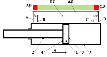
is the value of the control current in the electro-hydraulic valve of the shock absorber (the first control parameter of the shock absorber); [image:3.595.313.538.274.393.2]q
is a coordinate, determining the position of the piston 1 (Fig. 1) - the distance between this piston and its center position in the work cylinder 3 (the second control parameter of the shock absorber). In the Fig. 1 we have: 1 is the piston; 2 is piston rod; 3 is the work cylinder; 4,5 are back and front sides of the piston.Fig. 1. Scheme of telescopic shock absorber
In the Fig.1 the electro-hydraulic valve is not shown. The main determining regulation component acting on the adaptive shock absorber is, of course, the magnitude of the control current
i
. Mainly, it is variation of value ofi
, that allows us to get the «infinite» (hyper-wide) control range of the dissipative characteristics of the adaptive shock absorber.Depending on the type of function
i
i
(
t
)
and the method of its formation, four variants of the organization of the operational control of the dissipative characteristics of the shock absorber may occur:1.1. Autonomous mode in which the controlled variable is constant, i.e.
const
i
. (1) This mode is the most simple design variant of the control of the dissipative characteristics of the shock absorber. It is realized by natural internal automatism. This mode is limited by zone BC (Fig. 1), and it is approximately 93-95% of the maximum stroke of the piston in compare with the total work area AD. In this mode operating characteristic of the shock absorber remains unchanged and consists of a single curve, namely: curve 1 in rebound phase, and curve 4 in the contraction phase (Fig. 2).piston to the extreme positions A and D, the degree of damping of the shock absorber starts to increase automatically and progressively. Force Q, acting on the piston 1 (Fig. 1) and, consequently, on the rod 2, starts to increase as well. The corresponding curve of the characteristic starts to approach gradually to the y-axis, consistently taking up the positions 1, 2 (Fig. 2), etc.
Fig. 2. Operating characteristics of the shock absorber at constant operating influence
Finally, in the limit, when the piston is in the leftmost position, in which the left side 4 of the piston takes the position A (Fig. 1), the characteristic will automatically be aligned with the upper beam 3 of y-axis. In this position it automatically occurs the mode of “self-blocking”, in which the shock absorber is converted into a single rigid element and the further movement of the piston 1 lefter position A is impossible.
We emphasize, that in this mode of operation there is a «one-way blockage» of the shock absorber. The similar situation occurs in the compression phase, when the curve of the characteristic takes consistently the positions 4, 5, and 6. Thus, in this mode, the control of the dissipative characteristics of the shock absorber takes place only in the zones AB and CD of intensive adaptive damping of the shock absorber. Moreover, this control is carried out automatically, due to the design features of the piston-cylinder assembly.
It should be emphasized that the above-mentioned extremes, limiting positions A and D of the piston, described by segments 3 and 6 of the work characteristics, are according to the second variant of the organization of process of the control of the dissipative characteristics of the shock absorber. In this case we have the following mode.
1.2. Interlock operating mode of the shock absorber in which the absorber is converted into a single rigid unit. This mode, as it was mentioned above, is automatically provided when the piston occupies the extreme positions A and D (Fig. 1). However, the interlock operating mode, in addition to the above-described embodiment, may also be implemented at any time and at any position of the piston by appropriate values of the control current
i
.The next, the third embodiment of the organization of operational control of the dissipative characteristics of the shock absorber is as follows.
1.3. Manual mode.
This mode is the mode of forced control of the characteristics of the shock absorber by a driver of the vehicle. This mode is primarily characterized in that, in contrast to (1),
= varia. (2) The implementation of condition (2) is provided
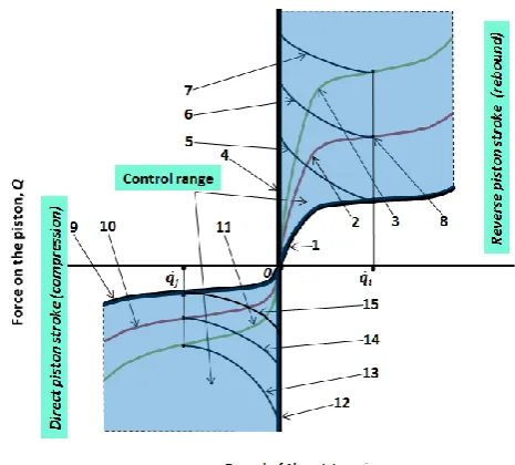
[image:4.595.319.552.253.463.2]«manually» by the driver of the vehicle. Control range of the operating characteristics of the shock absorber on the rebound phase is a set of infinitely continuous family of curves 1 ... 3 and the segment 4 (Fig. 3), continuously filling the entire first quadrant of the coordinate plane Q0 .
Fig. 3. Operating characteristics of the shock absorber at variable operating influence
Indeed, firstly, because degree of damping of the shock absorber can be made very small by choosing of the design parameters of the piston-cylinder assembly and electro-hydraulic valve. In other words, the curve 1 in Fig. 3 can be «infinitely close» to the x-axis. Secondly, it is due to the choice, according to (2), the value of control current i The degree of damping of the shock absorber can increase indefinitely, until the implementation of the interlock operating mode in which the characteristic of the shock absorber aligns with the beam 4.
Thus, we can conclude that the proposed design schemes of the adaptive shock absorbers allow us to implement an «infinite» adjustment range of the dissipative characteristics, i.e. to implement the hyper-wide range of the regulation of the dissipative characteristics.
has the segment 4 or 12 respectively (Fig. 3) as the operating characteristic.
In addition to these features, the present mode has another very useful practical quality, namely: the ability to implement in any position of the piston and at any time the interlock operating mode. Suppose that the shock absorber is working according to the characteristic 2 (Fig. 3). Suppose that for some value of the velocity of the piston
q
q
i, for example, at the position 8, we decided to block it, in other words, to transform it into a single rigid unit. The driver gives the corresponding signals to the control unit, selects a predetermined value of the control current i on the electro-hydraulic valve. In this case, the shock absorber automatically passes at the position 8 from the characteristic 2 to the curve 6 and, further, at the time of stopping of the piston to the segment 4.A similar result holds for the phase of “compression”. It should be noted that, in contrast to the case considered in the analysis of the autonomous mode of the shock absorber, the implementation of «two-way lock», when the piston are blocked in all directions simultaneously, is reached by the value of the current
i
.The last, the fourth variant of the organization of the operational control of the dissipative characteristics of the shock absorber is as follows.
1.4. Automatic control.
This mode satisfies the condition (2). However, the control impact is carried out automatically in accordance with the established program. The performance and functionality of the shock absorber correspond to the previous mode.
B. The elastic element with a nonlinear characteristic and automatic optimization of the localization of the operating zones
We recall the main features of our developed elastic elements. Firstly, operating characteristics, namely: the dependence of the effort on the elastic element from its deformation is essentially nonlinear. Secondly, at each point of the operating characteristic only those parts of the elastic element work, in which the voltage does not exceed a predetermined value. The rest parts of the elastic element are consistently being excluded from subsequent work. As it already has been mentioned, we have limited the maximum stresses in the elastic element of the value of 800 MPa.
In the following data to evaluate the effectiveness of our developed designs we compare the relevant characteristics of existing real prototypes traditionally used at present elastic elements with linear performance characteristics that work in similar conditions and have similar basic sizes. For a quantitative evaluation of the technical advantages of our designs of the resilient elements we consider the generally accepted valuation parameters:
с = , (3)
kd= Qmax/Qs , (4)
Rd = - Qs×(qmax – qs). (5)
Here we have:
Q is force on the elastic element;
q is deformation of the elastic element;
Qmax is maximum force on the elastic element; qmax is maximum deformation of the elastic element; Qs is static load on the elastic element;
qs is static deformation of the elastic element;
с is stiffness of the considered part of the elastic element;
kd is dynamic factor;
Rd is dynamic capacity of the elastic element of the
suspension.
In addition to the conventional parameters (3) - (5), we consider some additional relative values:
Kc = c1/cp , (6) KQ = Qmax,1/Qmax,p , (7) KR = Rd,1/Rdp . (8)
Here we have:
c1 is stiffness of considered part of the experimental model
of the elastic element;
cp is stiffness of considered part of the elastic element of the
prototype;
Qmax,1 is the maximum force on the experimental sample of
the elastic element;
Qmax,p is the maximum force on the elastic element of the
prototype;
Rd,1 is dynamic capacity of the experimental sample of the
elastic element of the suggested suspension;
Rdp is the dynamic capacity of the elastic element of the
suspension of the prototype.
[image:5.595.316.564.488.725.2]We have developed two designs of the elastic elements with non-linear characteristics and automatic optimization of the localization of the operating zones. These designs are fundamentally different from each other. Their operating characteristics are shown in Fig. 4 and Fig. 5.
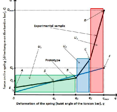
Fig. 4. Operating characteristics of the elastic element (the first variant)
of the elastic element with a nonlinear characteristic and automatic optimization of the localization of the operating zones developed by us - the curve ABCD. Our elastic element is designed for the adaptive suspension of vehicles, including the adaptive shock absorber.
These characteristics describe the actual elastic elements. The presence of buffers of rebound and compression is not taken into account, because in our designs there is no need to use them.
In the operating characteristic of the elastic element, in this case, one can distinguish three following segments:
• segment U1 is the segment of «comfort movement of
the vehicle», that corresponds to the interval AB;
• segment U2 is the segment of increased deformation of
the elastic element, that corresponds to the interval BC, and • segment U3 is the segment of high deformation of the
elastic element, that corresponds to the interval CD.
Direct comparative analysis of the designs gives the following results:
Kc,U1 = 0.5; Kc,U2 = 4.49; Kc,U3 = 32.54; kd,p = 1.56; kd,1 = 5,33; KQ = 6.1; KR = 3.37. (9)
Here we have:
Kc,Ui is the coefficient Kc, calculated for the segments Ui,
i ;
kd,p is the dynamic factor of the prototype;
kd,1 is the dynamic factor of the experimental model of the
elastic element.
Let us comment on the results (9).
1. In the “comfort zone” U1, where the elastic
deformation q of the suspension element is relatively small (the suspension works in the neighborhood of the point S, corresponding the static load Qs, and thus the static
deformation of the elastic member qs), stiffness of the elastic
element twice less than it is in the prototype. Thus, in this segment the vehicle suspension is twice softer than into the mainstream designs. Therefore, comfort of movement of the vehicle rises sharply.
2. If road conditions are getting worse, elastic deformation of the suspension element increases and passes, for example, to the segment U2.. Within this segment, the
stiffness of the elastic element is considerably greater than it is in the prototype. In real designs the stiffness of the characteristic in the segment U2 is 4.49 times greater in
comparison with the prototype. It allows us to solve more effectively the problem of stabilization of the vehicle and to stabilize its body.
3. Finally, under further increasing of the elastic deformation of the suspension element, i.e. when the suspension works in the segment U3, the stiffness of the
elastic element is order greater than the stiffness in the prototype. In actual designs we succeeded in increasing the stiffness in 24 times. And it should be noted that this is not the limit. This property of our developed elastic elements helps us to solve the problem of stabilization of the vehicle and stabilize its body even more effectively.
4. Very high values of the coefficients kd,1, KQ, and KR
allow us to conclude that, firstly, there is no any need to use buffer of compression, and, secondly, large deformations of the elastic element, i.e. large vibrations of the vehicle body are highly effectively constrained.
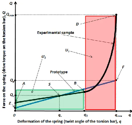
[image:6.595.321.548.98.312.2]In addition to the options discussed above, we have developed an elastic element that implements the operating characteristic shown in Fig. 5.
Fig. 5. Operating characteristics of the elastic element (the second variant)
In contrast to the case displayed in Fig. 4, this characteristic has two segments: U1 and U3. In the segment U3 the operating characteristic is essentially nonlinear and
is displayed by smooth curve. This allows during the movement outside the comfort zone, i.e. outside the segment
U1, significantly (in comparison with the case displayed in
Fig. 4) to reduce dynamic loads on nodes, vehicle body, and passengers.
Direct comparative analysis of the designs gives the following results:
Kc,U1 = 0.5; Kc,qmax = 62; kd,p = 1.56; kd,1 = 6.1; KQ = 3.9; KR = 3.28. (10)
Comparative analysis of the results (9) and (10) shows that the elastic element with the characteristic shown in Fig. 5 will have even better operating characteristics than the variant corresponding to Fig. 4.
Thus, with help of our developed elastic elements, the suspension of the vehicle in the comfort zone will be significantly softer, and, at the same time, it will solve the problem of stabilization of the vehicle and its body more effectively. In addition, it should be taken into consideration that the proposed designs of the elastic elements have significantly higher dynamic capacity and higher coefficient of dynamic than the prototype.
It is also necessary to note that there is the following important advantage of the suggested elastic elements. We managed to implement the principle of automatic optimization of localization of the operating zones. It means that if stresses, acting in some zone of the elastic element, reach a predetermined maximum value, then this zone is automatically excluded from the future work.
Thus, when the process passes on the area U2, zone of
predetermined maximum, is excluded from further work, and, when the process passes on the area U3 , it is excluded
the following, another zone. Consequently, it provides the optimization of the use of the elastic properties of the material of the elastic suspension elements of the vehicle.
C. The adaptive suspension of vehicle
Let us consider the operating characteristic of the elastic element under the assumption of using this element in conjunction with the adaptive shock absorber in the vehicle suspension. In fact, we consider adaptive suspension system of the vehicle, including the elastic element and the adaptive shock absorber.
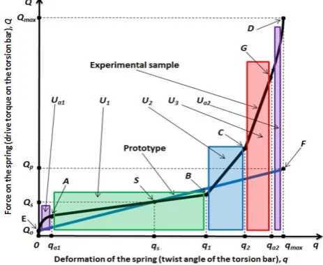
Fig. 6 presents the linear characteristic of the prototype of the elastic element (line EF) and the combined operating characteristic of the experimental sample with the developed elastic element and the adaptive shock absorber (OASBCGD curve).
This combined characteristic consists of five sections -
Uа1, U1, U2, U3, and Uа2.
Here we have
is deformation of the elastic element and, at the same time, the coordinate determining position of the piston in the work cylinder of the shock absorber;
Uа1 and Uа2 are the segments of intense damping
corresponding the zones AB and CD (Fig. 1);
U1 is the segment of “comfort movement of the vehicle”; U2 is the segment of increased deformation of the elastic
element; and
[image:7.595.319.552.280.468.2]U3 is the segment of high deformation of the elastic element.
Fig. 6. Operating characteristics of the elastic element based on the availability of the adaptive shock absorber (the first variant)
Set of the segments U1, U2, and U3 corresponds to the
zone BC (Fig. 1), and set of the segments Uа1, U1, U2, U3,
and Uа2 (Fig. 1).
Here are the main key features of the suggested suspension system of the vehicles.
1. In the segment of “comfort zone” U1, where the
deformation of the elastic element is relatively small (the suspension works in a neighborhood of the point S, corresponding static load), the stiffness of the elastic element, i.e. the stiffness of the interval AB of the
characteristic, is twice smaller in comparison with the prototype.
2. If the road conditions are getting worse, the elastic deformation of the suspension element increases and passes, for example, to the segment U2, where the stiffness of the
elastic element of the experimental sample is several times greater than it is in the prototype. In some actual designs the stiffness of the characteristics on the segment U2, i.e. the
stiffness of the interval BC of the characteristic, in 4-8 times more than it is in the prototype.
3. With further increasing of the deformation of elastic element within the segment U3, the stiffness of the elastic
element, i.e. the stiffness of the interval CG of the characteristic, is more than an order of magnitude greater than the stiffness of the prototype.
[image:7.595.49.281.420.610.2]Fig. 7 shows the operating characteristics of the elastic element corresponding to the constructive embodiment described in Fig. 5.
Fig. 7. Operating characteristics of the elastic element based on the availability of the adaptive shock absorber (the second variant)
As well as we have done the analysis of the relevant scheme (Fig. 5), it should be noted that in contrast to the case displayed in Fig. 6, the characteristic consist of four sections: Uа1, U1, U3, and Uа2. And in the segment U3 the
characteristic is nonlinear and displayed by smooth curve. This allows during movement outside «the comfort zone» significantly, in comparison with the case described in Fig.6, reducing the dynamic loads acting on the nodes, transport equipment, and passengers.
Thus, by using our developed elastic elements of the vehicle in the “comfort zone”, the suspension will be significantly softer, and, at the same time, and it will more effective solve the problem of stabilization of the vehicle and its body.
existence of the adaptive shock absorber, proposed interpretation of the elastic characteristics is not traditional. However, for the consideration of the adaptive shock absorbers, it is acceptable.
V. CONCLUSION
We have developed fundamentally new, having no analogues in the world practice of transport engineering, the original designs: 1) the lockable adaptive shock absorber with a hyper-wide control range of dissipative characteristics; 2) the elastic element with the nonlinear characteristic and the automatic optimization of localization of working zones. Our suspensions allow: 1) implementing the hyper-wide control range of dissipative characteristics; 2) realizing the "self-blocking" mode at any time; 3) implementing any pre-defined dissipative characteristics of the marked hyper-wide control range; 4) adjusting the dissipative characteristics of a vehicle while driving in manual mode, by direct control action, and by automatic control; and they have some other advantages. Usage of our suggested designs of the suspensions will help more effective to solve the problem of stabilization of the vehicle and its body.
Summarizing the above, and based on the present state of our experience of work in the development of the adaptive suspension vehicle, the achieved level of our scientific expertise and our research capacity in this field, we can confidently state that, in the case of our proposed designs of the adaptive suspension system, the vehicle will be equipped with this suspension system that for technical and economic indicators of quality will surpass for many years the known world analogues, leaving far behind the world's major competitors.
We have installed the developed design of the suspension on the car "Lada-Granta." The experimental results confirmed the validity of the theoretical propositions.
REFERENCES
[1] A. Truscott, and P. Wellstead, “Adaptive Ride Control In Active Suspension Systems. Vehicle System Dynamics,” International Journal of Vehicle Mechanics and Mobility, Vol.24, Issue 3, 1995, pp. 197-230.
[2] A. F. Dubrovskiy, O. A. Dubrovskaja, S.A. Dubrovskiy, and S. V. Aliukov, “On the analytic representation of elastic-dissipative characteristics of the car's suspension,» Bulletin of the Siberian State Automobile and Road Academy, 2010, № 16, pp. 23 - 26.
[3] J. Raympel, “Vehicle chassis: suspension components,” Transl. from German, Moskow, Engineering, 1997, 285 p.
[4] R. Rothenberg, “Car suspension,” Ed. Third, revised. and add., Moscow, Mechanical Engineering, 2002, 392 p.
[5] A. Derbaremdiker, “Hydraulic shock absorbers of vehicles,” Moscow, Mechanical Engineering, 1999, 302 p.
[6] N. Reza, “Vehicle Dynamics: Theory and Application,” Spring, 2012, 455 p.
[7] I. Eski. and S. Yıldırım, “Vibration control of vehicle active suspension system using a new robust neural network control system,” Simulation Modelling Practice and Theory, vol. 17, № 5, 2009, pp. 778–793.
[8] H. Jing, X. Li, and H. R, Karimi, “Output-feedback based H∞ control for active suspension systems with control delay,” IEEE Transactions on Industrial Electronics, vol. 61, № 1, 2014, pp. 436– 446.
[9] U. Aldemir, “Causal semiactive control of seismic response,” Journal of Sound and Vibration, vol. 322, № 4-5, 2009, pp. 665–673. [10] A. F. Dubrovskiy, S. A. Yershov, A. A. Lovchikov, “Analysis of