Thermally Stable Conditions during Capillary Shaping of Bent Components
+1Jun Yaokawa
1,+2, Yasushi Iwata
1, Yoshio Sugiyama
1, Mitsuhiro Kobayashi
2and Yuta Egawa
21Toyota Central R&D Labs., Inc., Nagakute 480-1192, Japan
2Toyota Motor Corporation, Toyota 471-8571, Japan
Capillary shaping is an upward pulling solidification technique for obtaining aluminum alloy hollow products with high structural stiffness
and high mechanical properties. Recently, hollow frames with inner ribs and bent geometry are increasingly desired for optimizing car body
stiffness and design of lightweight car body structures. Capillary shaping is an attractive process for manufacturing these components. However,
it is necessary to control thermal conditions during the pulling process for fabricating bent products with high thickness accuracy, since thermal
conditions influence the thickness of products and vary at the bent section due to differences in the pulling rates at inner and outer positions. In
this study, the thermally stable conditions during the capillary shaping of aluminum alloy bent tubes were investigated. It is found that bent tubes with high thickness accuracy can be fabricated without any automatic controls of cooling conditions when thermally stable pulling conditions are
maintained. [doi:10.2320/matertrans.F-M2018818]
(Received February 8, 2018; Accepted April 5, 2018; Published May 18, 2018)
Keywords: capillary shaping, aluminum, hollow geometry, self-stabilization, thickness
1. Introduction
Currently, automobile lightweighting is one of the most important concerns in the automotive industry. Since the 1980s, permanent mold casting and high-pressure die casting have been used to shape aluminum alloys for powertrain components. In recent years, demand has increased for material substitutions in car bodies and chassis to reduce the weight of electric vehicles, hybrid vehicles, and fuel cell vehicles.
Aluminum alloy frames are used in car bodies to reduce weight and improve ride comfort. Due to the low Young’s modulus of aluminum alloys, shapes with high structural stiffness, such as hollow geometries with interior ribs, are desired for aluminum frame components. Variable cross-sections and bent geometries are also required for optimizing the weight and design of the car body structure. Since conventional manufacturing processes are unsuitable for fabricating these complicated aluminum frame shapes, new manufacturing techniques are needed.
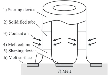
Mold-less upward-pulling casting (hereafter, capillary shaping) is a solidification technique by which hollow products with interior ribs, variable cross-sections, and bent geometries can be fabricated directly from an aluminum alloy melt.17) Figure 1 is a schematic illustration of the capillary shaping technique. In this process, a melt column with a controlled cross-section is formed above the melt surface using starting and shaping devices. Products with the desired shape are fabricated by withdrawing the starting device along a pulling path while cooling the position above the melt column. The directional solidification in this process permits shaping of wrought aluminum alloys with superior mechanical properties, for example, 6000 and 7000 series alloys, despite their high solidification cracking sensitivity.8) Therefore, capillary shaping is an attractive process for fabricating tubular components.9)
In the capillary shaping technique, precise product thickness can be achieved by maintaining the melt temperature, pulling rate, and cooling systems at a thermally stable condition,7)using feedback and feedforward controls. When fabricating bent geometries, however, cooling efficiency becomes insufficient due to differences in the pulling rate at the inner and outer positions of the bend radius. In this study, we performed capillary shaping of straight and bent cylindrical specimens to investigate the thermal stability needed to maintain wall thickness uniformity in the bent section. We also identify conditions that maintain thermal stability and can fabricate bent cylindrical specimens with a highly uniform wall thickness without adjusting the cooling conditions.
2. Experimental Procedure
2.1 Capillary shaping apparatus
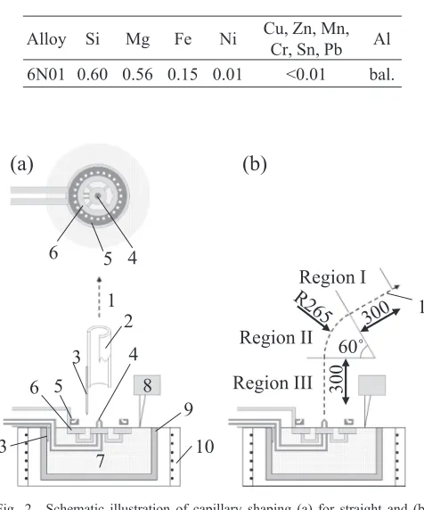
Straight and bent cylindrical specimens of JIS-6N01 aluminum alloy were fabricated by the capillary shaping technique. Table 1 lists the chemical composition of the alloy, and Fig. 2 shows the experimental setup. The melt was kept at 979 K in an alumina crucible. A shaping device with a circular opening having a 56 mm outer diameter and 46 mm inner diameter (5 mm opening width) was used for defining
4) Melt column 2) Solidified tube 1) Starting device
7) Melt 6) Melt surface
5) Shaping device 3) Coolant air
Fig. 1 Schematic illustration of capillary shaping of hollow product.
+1This Paper was Originally Published in Japanese in J. JFS89(2017) 396
401.
+2Corresponding author, E-mail: e1454@mosk.tytlabs.co.jp
[image:1.595.330.520.312.444.2]the cross-section of the melt column. The shaping device was made of 2 mm thick SUS304 stainless steel plate powder-coated with BN. The device was positioned so that its upper surface coincided with the surface of the melt. Specimens were cooled and solidified by air blown from inner and outer cooling nozzles. Coolant air for the inner nozzle was supplied through a melt-immersed stainless steel pipe covered with ceramic insulator. Flow rates of coolant air from the outer and inner nozzles were 260 and 60 L/min, respectively. The starting device was an A6063 aluminum alloy tube with 50 mm outer diameter and 48 mm inner diameter.
Pulling of specimens was started by dipping the starting device into the melt, waiting for 10 s, and withdrawing the device with the coolant air blowing. Then, the starting device was moved along the pulling path. The falling melt level associated with melt consumption was measured with a laser positioning meter for feedback control of the pulling rate and positioning of the shaping device.
2.2 Thermal stability during vertical pulling of straight cylindrical specimen
Straight cylindrical specimens 300 mm long were vertically withdrawn, as shown in Fig. 2(a), at constant pulling rate between 0.4 and 1.4 mm/s with fixed cooling conditions, and the thermally stable pulling conditions for obtaining specimens with high thickness uniformity were determined. Up to three specimens were fabricated under each pulling condition. A thermocouplefixed 140 mm below the bottom of starting device was concurrently withdrawn to record the vertical temperature distribution.
In this study, the specimen wall thickness was independent of the use of the thermocouple. However, the specimen thickness increased at the beginning of the pulling process because of decreasing melt temperature below the shaping device. The specimen thickness and melt temperature stabilized after the specimen length exceeded 100 mm. Thus, the vertical temperature distribution could be obtained from 40 mm below the melt surface.
2.3 Thermal stability during rotary pulling of bent cylindrical specimen
A cylindrical specimen with bent geometry was fabricated as shown in Fig. 2(b) using the same fixed cooling conditions. This specimen was composed of three sections: a straight section 300 mm long (region I), a bent section with 265 mm radius and 60° bend angle (region II), and a second straight section 300 mm long (region III). The bent and straight sections were formed by rotary and vertical pulling, respectively. To obtain a steady-state pull, the cylindrical specimen was vertically withdrawn for 200 mm before formation of region I was started. The pulling rate was 0.5 mm/s on the straight pulling path, and the pulling rate during the rotary pulling was between 0.547 mm/s at the outer bend position and 0.452 mm/s at the inner bend position.
2.4 Determination of solid-liquid interface height The solid fraction was derived from the temperature distribution measured during the vertical pulling of the straight cylindrical specimen section, using Scheil’s relationship between the solid fraction and the temperature of the 6N01 alloy for considering the micro-segregation caused by solute redistribution. This relationship was calculated with the Thermo-Calc software version S using the SSOL4 database with a calculation temperature interval of 0.01 K. Temperatures at the beginning and end of solidification were 926.8 K and 830.2 K, respectively. The solid-liquid interface height was defined as the position of the beginning of solidification.
2.5 Wall thickness of cylindrical specimen
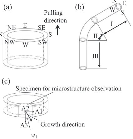
As mentioned above, the wall thickness of cylindrical specimen stabilized after its length exceeded 100 mm. Thus, the straight specimen sections were cut 140 mm from the starting device, thickness b was measured at the eight locations (N, NE,+, NW) shown in Fig. 3(a), and the mean thicknessbmwas determined from these measurements. The thermocouple was set at location N. The thickness of the bent specimen sections was measured at the four locations (N, E, S, and W) shown in Fig. 3(b) at 40 mm intervals along the pulling path in regions I and III and at 4° or 8° intervals in region II.
2.6 Identification of growth direction
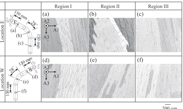
Growth direction of the ¡-Al phase dendritic grains was determined along the pulling path at locations E and W. The microstructures were observed at the same positions as the thickness measurements by a polarization microscope after anodization (Barker’s etching). The cylindrical coordinate system shown in Fig. 3(c) was used for measuring the growth
1
2
3
4
5
6
7
1
8
4
5
6
60
˚
Region I
Region II
Region III
300
(a)
(b)
3
9
10
Fig. 2 Schematic illustration of capillary shaping (a) for straight and (b)
for bent-cylindrical specimens, 1) pulling path, 2) starting device, 3) thermocouples, 4) inner cooling nozzle, 5) outer cooling nozzles, 6) shaping device, 7) melt, 8) laser position meter, 9) alumina crucible, and (10) electric resistance heater.
[image:2.595.50.288.81.367.2]angle ¼1 between the primary dendrite trunks and the A3 axis, where the A1 axis was an angular direction, the A2 axis was a radius direction, and the A3 axis was antiparallel to the pulling direction. The growth angle¼1of six grains at each location was measured from microstructures perpendicular to the A2 axis.
3. Results and Discussion
[image:3.595.322.526.70.266.2]3.1 Cross sections of straight cylindrical specimens Figure 4 shows the relationship between the pulling rate and wall thickness of the straight cylindrical specimen sections. In the plot, circles and error bars represent the mean thickness bm and thickness distribution between the maximum and minimum thickness, respectively. Cross-sections of uniformly thick (5.15¯b¯5.40 mm) and non-uniformly thick (2.95¯b¯4.29 mm) specimens are also shown in Fig. 4. When the pulling rate was between 0.4 and 0.57 mm/s, the mean thickness was independent of the pulling rate and specimens with uniform thickness were formed. However, when the pulling rate exceeded 0.57 mm/s, specimen walls became thinner with increasing pulling rate, and the thickness uniformity worsened. At pulling rates slower than 0.4 mm/s, the pulling process was interrupted by solidification under the shaping device.
Variation in the thickness uniformity can be recognized from the thermal stability.7)At thermally unstable conditions, the wall thickness of specimens tended to decrease with increasing pulling rate due to insufficient cooling efficiency. In this study, pulling rates greater than 0.57 mm/s were thermally unstable, and cylindrical specimens pulled from the melt formed walls thinner than the opening width of the shaping device. Under this circumstance, the non-uniformity of the cooling efficiency and/or of the melt temperature under the shaping device resulted in thickness irregularity. At thicker parts of the wall of cylindrical specimen, for instance, the coolant air extracts much heat from the specimen due to
a narrower distance between the cooling nozzles and the specimen surface, reducing the melt temperature at this position more effectively. In contrast, at thinner parts, both the heat extraction and the melt temperature decrease are less than those of the thicker part. Thus, the thickness of the thicker part increases whereas that of the thinner part decreases, and the thickness irregularity becomes pronounced. In contrast, pulling rates ranging from 0.4 to 0.57 mm/s were thermally stable, where the wall thickness of cylindrical specimen was almost the same as the opening width of the shaping device. In this situation, the strong cooling and/or the low melt temperature makes the solid-liquid interface move downward, decreasing the heat extraction from the specimen to the coolant air, so that the thickness become uniform.
To confirm the validity of the thermal stability theory, the relationship between the solid-liquid interface height and thickness of the specimen was determined according to vertical temperature distribution. Figure 5 shows the vertical distributions of temperature and solid fraction obtained at the pulling rate u=0.6 mm/s. The wall thickness of this
specimen ranged between 4.19 and 5.10 mm and was Pulling
direction E
W
N S
N
S E W
I
II
III SE
NE
NW SW
ψ1
A3 A1 A2
Growth direction
Specimen for microstructure observation
(a)
(b)
(c)
Fig. 3 (a), (b) Definitions of parts for micro-structural observation.
(c) Definition of dendrite growth inclination angles.
Mean thickness of each tube Minimum thickness of each tube Maximum thickness of each tube
Pulling rate, u /mm·s-1
Thickness,
bm
/m
m
0.4 0.57
20 mm Uniform
cross-section
Non-uniform cross-section
Fig. 4 Influence of pulling rate on thickness of straight cylindrical
specimens.
Distance from melt surface, x/mm
Tem
perature
T
/K Liquidus Temp.
Temp.
Solid fraction
Solid fraction
Fig. 5 Vertical distributions of temperature and solid fraction of straight
[image:3.595.66.279.76.298.2] [image:3.595.317.535.318.477.2]5.08 mm at the temperature measurement position. Temperature of the melt or specimen decreased as the temperature measurement position became elevated. The solid-liquid interface was located 3 mm above the melt surface, which agreed with the formation of the melt column above the melt surface sustained by the surface tension or the oxide film. It was also found that the melt temperature
fluctuated below the melt surface because of natural convection. The solid fraction increased steeply from zero to 0.5 within 1 mm above the solid-liquid interface, indicating the shape of the specimen was defined within this short range because the fluidity of 6N01 alloy was quite low when the solid fraction was 0.5 and higher.
Figure 6 shows the relationship between solid-liquid interface height Z and specimen thickness b for various pulling rates. The solid-liquid interface height decreased as the thickness at the temperature measurement increased. This phenomenon was coincident with that of pure aluminum and Al12Si alloy.7) Since a steep @Z/@b enhances the thermal stability induced by the movement of the solid-liquid interface, specimens with uniform thickness can be obtained when the thickness approached the opening width of the shaping device.7) As shown in Fig. 4, pulling rates slower than 0.57 mm/s produced uniform wall thicknesses in straight sections.
3.2 Cross sections of bent cylindrical specimens This section examines fabrication of the bent section of the cylindrical specimen. The pulling rates at the outer and inner radius positions during the rotary pulling were 0.547 and 0.452 mm/s, respectively. These rates satisfied the pulling rate conditions (0.4¯u¯0.57 mm/s) for obtaining uniform
wall thickness in the straight section under constant cooling. As shown in Fig. 7, the cylindrical specimen had an overall uniform appearance.
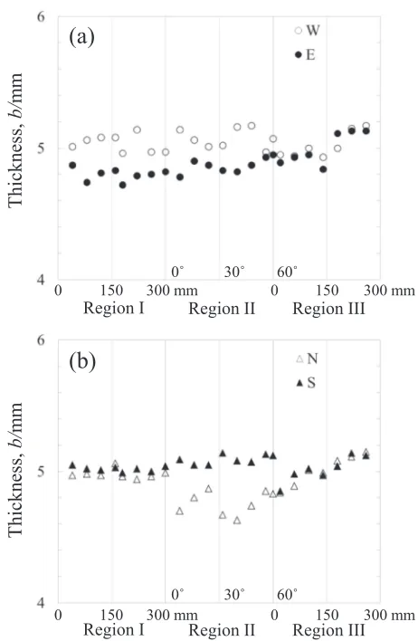
Figure 8 shows the thickness distributions of the specimen shown in Fig. 7. Because of the constant pulling rate of 0.5 mm/s at locations W and E during the rotary pulling, the thickness in these locations changed slightly and continuously from regions I to III. A slight scattering in the thickness was found in regions I and II, and it disappeared in
region III. Vibration of the melt column surface during the pulling process seemed to affect the thickness scattering, although more focused study is required to clarify how the thickness varied in this way. At the outer position (location N), the wall in region II became thinner due to the increased pulling rate at this location during the rotary pulling. In contrast, at the inner position (location S), the thickness at regions I, II, and III was almost the same in spite of the pulling rate decrease in region II. Thickness distribution of this specimen was within 4.9«0.3 mm, demonstrating that a bent cylindrical specimen with highly
Thickness, b/mm
Solid
-liqui
d interface
height,
Z
/m
m 6N01
Al-12%Si 7)
99.8% Al 7)
Fig. 6 Relationship between thickness and solid-liquid interface height of
straight cylindrical specimen in various aluminum alloys.
Pulling path
Fig. 7 Appearance of bent cylindrical specimens.
150 300 mm 150
0 0 300 mm
0˚ 30˚ 60˚
Region I Region II Region III
Thickness,
b/
mm
(a)
(b)
150 300 mm 150
0 0 300 mm
0˚ 30˚ 60˚
Region I Region II Region III
Thickness,
b/
mm
Fig. 8 Thickness distributions in bent cylindrical specimens. (a) positions
[image:4.595.59.284.70.250.2] [image:4.595.354.491.70.215.2] [image:4.595.311.542.251.605.2]uniform wall thickness could be fabricated by the capillary shaping technique without changing the cooling conditions.
Figure 9 shows the microstructure of a bent cylindrical specimen. The dendrite growth direction in regions I, II, and III at locations E and W aligned antiparallel to the pulling direction (A3) with inclination toward the outer side (location N), indicating that the solid-liquid interface at location N was the highest. The inclination of the dendrite growth direction during vertical pulling [panels (a), (c), (d), and (f )] also implied that pulling conditions in the experimental apparatus used in this study were non-uniform, causing lower cooling efficiency and/or higher melt temperature at location N compared with conditions at other locations. The change in pulling rate during the rotary pulling enhanced the difference in the solid-liquid interface height between locations N and S, increasing the inclination angles of the dendrite growth direction, as shown in Figs. 9(b) and 9(e).
Figure 10 shows the inclination angle distributions of the dendrite growth direction at locations W and E. The dendrite growth direction inclined about 10° toward location N in the straight section (region I), increased to about 30° in the bent section (region II), and decreased again to about 10° in the second straight section (region III). It was clear that the change in pulling rate from the vertical pulling (region I) to the rotary pulling (region II) caused a larger difference in the solid-liquid interface height between locations N and S. Due to the movement of the solid-liquid interface, the wall thickness remained uniform during the transition between vertical and rotary pulling.
Therefore, uniformly thick bent products can be fabricated by the capillary shaping technique under fixed cooling conditions by applying the movement of the solid-liquid interface height, when the pulling rate of the inner and outer positions during the rotary pulling stayed within the range for obtaining uniformly thick straight products during vertical pulling.
4. Summary
Bent cylindrical specimens were fabricated by the capillary shaping technique to investigate the thermal conditions affecting the wall thickness uniformity of the bent section. In addition, we determined the thermally stable conditions under which bent cylindrical specimens with highly uniform wall thickness could be obtained by this technique under
fixed cooling conditions. Ourfindings can be summarized as follows:
(1) Bent products with highly uniform wall thickness can be fabricated by the capillary shaping technique without changing the cooling conditions provided that the pulling rates are controlled. The rotary pulling rates at the inner and the outer radius positions of bent products must stay within the range of vertical pulling rates that produce uniform wall thickness in straight products. In this study, a uniform A3
A1 A2
(a)
(b)
(c)
(d)
(e)
(f)
200μm
Region I Region II Region III
Location W
Location E
N SE
W
150 mm
(d) (e)
(f)
A3 A1 A2
150 mm
WN S E
(a) (b)
(c)
Fig. 9 Polarized microscopic images of bent cylindrical specimens.
150 300 mm 150
0 0˚ 30˚ 060˚ 300 mm
Region I Region II Region III
Inclination
angle of dendrite growth direction Ψ1
(
˚
)
Fig. 10 Inclination angle of dendrite growth direction at positions W and
[image:5.595.309.547.348.517.2]wall thickness was produced by pulling rates between 0.4 and 0.57 mm/s. Within this range, both the straight and bent sections had uniform wall thickness under
fixed cooling conditions.
(2) In the capillary shaping technique, the wall thickness becomes uniform as a result of thermal stabilization induced by the movement of the solid-liquid interface. The mechanisms for thermal stability during straight and rotary pulling were the same. The height of the solid-liquid interface increased at the outer radius position because of the faster pulling rate, whereas it decreased at the inner position due to a slower rate. (3) The dendrite growth direction inclined toward the outer
position in the bent section because of the movement of the solid-liquid interface.
REFERENCES
1) A.V. Stepanov: Zh. Tech. Fiz.29(1959) 381.
2) A.V. Stepanov: Bull. Acad. Sci. USSR, Phys. Ser.33(1969) 1775.
3) V.V. Peller and S.P. Nikanorov:Handbook of Aluminum, vol. 1, Physical
Metallurgy and Processes, (CRC Press, 2003) p. 695.
4) A. Sato, Y. Ohsawa and G. Aragane:Mater. Trans. JIM30(1989) 55.
5) A. Sato, Y. Ohsawa and G. Aragane:Mater. Trans. JIM32(1991) 77.
6) A. Sato, Y. Ohsawa and G. Aragane:Mater. Trans. JIM33(1992) 66.
7) J. Yaokawa, Y. Iwata, Y. Sugiyama, N. Sugiura and Y. Furukawa:Acta
Mater.104(2016) 180.
8) J. Yaokawa, Y. Sugiyama, Y. Iwata, N. Sugiura and Y. Furukawa: Proceedings of the 72nd World Foundry Congress, Nagoya, (World Foundry Organization, 2016) O-29.