Shunsuke Sasaki
1,*2, Hiroto Goto
2, Tatsuro Katsumura
1and Masaru Miyake
3 1Steel Research Laboratory, JFE Steel Corp., Handa 475–8611, Japan2Steel Research Laboratory, JFE Steel Corp., Chiba 260–0835, Japan 3Steel Research Laboratory, JFE Steel Corp., Fukuyama 721–8510, Japan
The sizing press process was developed to achieve extensive width reduction and yield improvement. The slab head and tail shapes after sizing pressing are important in crop loss reduction and stable operation. This study was carried out to investigate the deformation behavior of the slab head in sizing pressing with back pressure. Finite Element Analysis and a model experiment were conducted to study the deformation behaviors of the slab head thickness profile and plan-view pattern. It was found that width reduction by the back-pressure method enables con-trol of the slab head shape. The maximum thickness of the central part of the slab head was reduced and the plan-view pattern changed from a fishtail shape to a tongue shape when back pressure was applied during sizing pressing. [doi:10.2320/matertrans.P-M2016822]
(Received December 21, 2015; Accepted May 21, 2016; Published July 15, 2016)
Keywords: sizing press, finite element analysis, nonsteady deformation, planar shape, thickness profile, back pressure
1. Introduction
In the hot rolling process, slab width changing processes are used to adjust the width of slabs, which are cast with a constant width, to the various widths required in hot rolled steel strips. Because this makes it possible to consolidate the width of the slabs cast in the continuous casting process and realize synchronization/continuation with the hot rolling pro-cess, which has a relatively high production capacity, width adjustment is a key process for productivity improvement. Practical width adjustment processes include the edging-roll-ing process,1) in which a pair of opposing vertical rolls are
used, and the sizing press process,2–4) in which the slab is
advanced intermittently between a pair of opposing forging dies that repeatedly perform a width reduction operation, thereby reducing the width of the slab over its full length. In comparison with edging-rolling, the sizing press process can easily apply strain to the center of the slab width due to the long contact length between the slab and the dies during width adjustment. Therefore, the thickness increase in the slab width edge area after width adjustment can be sup-pressed, width return after horizontal rolling is slight, and width reduction efficiency is high. Moreover, since crop loss at the slab head and tail ends can be reduced, the sizing press is effective for expanding the amount of slab width adjust-ment and reducing unit material consumption5–7).
During slab width adjustment by the sizing press, the parts other than the slab width edges, where deformation is re-strained by contact with the dies, are free deformation areas. An appropriate shape control technology for the pressed shape of the slab head and tail ends, which are unsteady parts, is especially important since these parts are directly related to crop loss after horizontal rolling. In addition, unlike the dou-ble bulging shape (dog-bone shape) which can be seen in the steady part, the increased thickness profile at the head end of
the slab has a single bulging shape, in which a local thickness increase occurs in the center of the slab width.8) This
phe-nomenon causes problems such as poor roll bite in horizontal rolling and poor conveying of the material due to interference with the conveying rollers, particularly when the amount of width reduction is large.
In previous reports, the deformation behavior and width reduction load of free deformation areas during sizing press-ing, including the slab head and tail ends, were studied by model experiments, the upper bound method8,9) and the finite
element method (FEM)10,11). The effects of changes in the die
shape12), preforming position and feed rate on deformation
behavior8,9) were also clarified, and methods for improving
operational efficiency and product yield were proposed. During width reduction, a slab is subjected to some amount of external force due to contact with the pinch rollers which are used to advance the slab and the buckling prevention de-vice. However, no studies in connection with the active use of external forces to control the slab shape have been reported. In the free deformation area, deformation behavior is thought to change due to the external forces acting on the slab during width reduction. In particular, because deformation to the rolling direction occurs easily in the unsteady parts at the slab head and tail ends, it is thought that these unsteady parts are easily affected by external force applied to the slab during width reduction. Therefore, the aim of this paper was to in-vestigate the deformation behavior of the slab head end when back pressure is applied to the slab tail end by the sizing press. Model experiments with lead slabs and FEM analysis were performed to clarify this issue. In addition, the effects of the back pressure load and the number of passes in which back pressure is applied on the deformation behavior of the slab and the controllability of the slab head end were also in-vestigated.
2. Experimental Method
2.1 Model experiment of width reduction using lead slab A model experiment without back pressure was conducted
*1
This Paper was Originally Published in Japanese in Journal of the JSTP 56 (2015) 979–985.
*2
to confirm the analytical accuracy of the FEM model, and fitting of the model was performed. Figure 1 shows the geom-etry of dies used in the experiment. The die material was S45C (ISO C45) steel. The dies had a 50 mm parallel part and a slope angle of 12 . Width reduction was performed with two dies arranged opposing each other. The dimensions of the lead slab are shown in Fig. 2. The slab had a rectangular par-allelepiped shape (length: 280, width: 120, height: 21 mm). The slab material was hard lead (antimonial lead containing 1%Sb). The experimental conditions are shown in Table 1. The amount of width reduction was defined as the difference from the total initial slab width (⊿w). Experiments were per-formed under the two conditions of ⊿w = 20 mm and 40 mm. The velocity of width reduction was 1 sec/mm of closure of the distance between the opposing dies (= ⊿w of 1 mm/sec). The starting position of width reduction was the position (shown by the arrow in Fig. 1) where the slab head position was 5 mm to the inclined side of the die from the intersection of the die parallel part and inclined part. The slab feed rate was constant at 30 mm. One pass was defined as the period from the completion of width reduction until width reduction was performed again after the specified slab feed. The width reduction experiment was performed by repeating this pro-cess. A lubricant was not used between the die and the slab during width reduction. After width reduction, the head thick-ness profile (Fig. 2 X-Y) and plan-view pattern (Fig. 2 X-Z) of the lead slab were measured. Horizontal rolling to the ini-tial thickness was performed with a rolling mill with 200 mm diameter rolls, and the plan-view pattern was also measured after this horizontal rolling.
2.2 Development of FEM model
An FEM model was developed in order to perform back
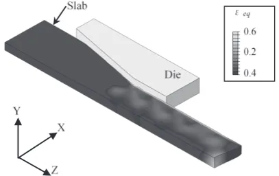
pressure control of the slab head during width reduction. The solver was Abaqus Explicit (6.13). An elastoplastic 3-dimen-sional stress analysis model was used. The analysis results (distribution of equivalent plastic strain) after 5 passes of width reduction at ⊿w = 40 mm using the developed model are shown Fig. 3. The model was a 1/4 model, assuming symmetry in the slab thickness and width directions. An anal-ysis of the horizontal rolling of the slab after width reduction until the initial slab thickness was obtained was also per-formed, assuming a horizontal rolling mill with the roll diam-eter of 200 mm. The dies and rolls were defined as rigid bod-ies. The deformation resistance of the antimonial lead shown in Fig. 4 was measured by a uniaxial compression test (room temperature) using a cylindrical test specimen with dimen-sions of φ6 and L10 mm. Values obtained by extrapolation up to plastic strain (true strain) of 1.0 were used. Because the strain rate during width reduction obtained by FEM was a maximum of 1.0 s−1 or less, deformation resistance of 0.1 s−1
was used at strain rates from 0.0 to 0.1 s−1, and values
ob-tained by interpolating the deformation resistance at 0.1 and 1.0 s−1 were used at higher strain rates. The analysis
condi-tions are shown in Table 2. The coefficient of friction between the lead slab and the dies and rolls was determined to be 0.28 Table 1 Experimental conditions.
Width reduction; ⊿w 20, 40 mm
Feed rate 30 mm/pass
Location of 1st. press 5 mm
Lubrication condition None
Table 2 Analytical conditions.
Solver Abaqus Explicit (6.13)
Friction coefficient 0.28
Back pressure /MPa 0.0, 2.5, 5.0, 7.5, 10.0 Fig. 1 Geometry of sizing press dies.
Fig. 2 Dimensions of lead slab.
Fig. 3 Equivalent plastic strain (εeq) contour for width reduction of 40 mm.
[image:2.595.323.527.70.198.2] [image:2.595.76.258.73.262.2] [image:2.595.339.512.237.381.2]by the sizing press, backward displacement occurs in the tail end of the slab due to deformation to the reduction direction during 1st pass reduction by the inclined part of the dies and
to the rolling direction during width reduction. Back pressure is defined as the pressure which can be applied to the slab tail end as a whole when backward displacement occurs during width reduction by an arbitrary number of passes in the direc-tion (Z direcdirec-tion) that suppresses backward displacement of the tail end. Five back pressure conditions (0.0, 2.5, 5.0, 7.5 and 10.0 MPa) were used. Application of back pressure is considered to influence the amount of backward displace-ment of the slab during width reduction. Therefore, the back-ward displacement during width reduction was measured from the 1st to the 3rd pass, and the results were also used for
fitting between the experiment and FEM and discussion of the influence on the head end shape. Backward displacement was defined as δB. As the measurement position, the position of the slab tail end before/after width reduction was mea-sured with a dial gauge in the lead slab experiment, and the node displacement of the tail end was measured in the FEM analysis. Other analysis conditions, such as the width reduc-tion ⊿w, feed rate, preforming position and horizontal roll-ing conditions were the same as those in the experiments with the antimonial lead. The effect of the back pressure applied during width reduction on the slab head end shape (deforma-tion behavior of the slab head end) was investigated by using the developed FEM model.
3. Results of Experiment and FE Analysis
3.1 Verification of FEM model accuracy
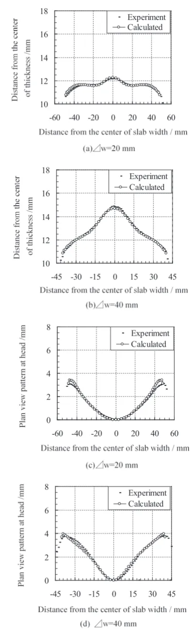
The thickness profiles and plan-view patterns of the slab head end after width reduction at ⊿w = 20 and 40 mm are shown Fig. 5(a)–(d), which show a comparison of the experi-mental results and FEM results. The slab head end thickness profiles and plan-view patterns showed good agreement un-der all conditions. Unun-der deformation by the sizing press, the slab head thickness profile displays a single bulge shape,8)
and the thickness increase of the slab edge is suppressed. This deformation behavior is attributable to the fact that strain eas-ily penetrates to the slab width center due to the long contact length between the die and the slab edges. This tendency is remarkable under the large width reduction condition of
⊿w = 40 mm. In this case, a large thickness increase occurs locally at the slab width center in comparison with ⊿w = 20 mm. On the other hand, regarding the plan-view pattern, it has been reported8) that a fish-tail shape formed at the head
end when width reduction was performed from the inclined part of the dies. The experimental results in the present study were also consistent with those results. Figure 6 shows the plan-view patterns after horizontal rolling to the initial thick-ness following width reduction under the two ⊿w conditions. In both the model experiment and the FEM analysis, the fish-tail shape formed when the width reduction was ⊿w =
[image:3.595.323.519.81.731.2]20 mm, and a convex tongue shape formed when ⊿w = 40 mm. Thus, the experimental and analytical results were in good agreement. The plan-view pattern of the head end after horizontal rolling is decided by a combination of the width thickness profile (thickness increase) after width reduction and the plan-view pattern. When ⊿w = 20 mm, the increase in the thickness of the slab width center after width reduction is small, and the shape is comparatively close to rectangular. As a result, it is considered that the fish-tail shape, which was built into the slab by width reduction, also remains after hor-izontal rolling. When ⊿w = 40 mm, it is thought that the thickness increase in the slab width center is elongated in the rolling direction by horizontal rolling, and in this case, the tongue shape is formed.
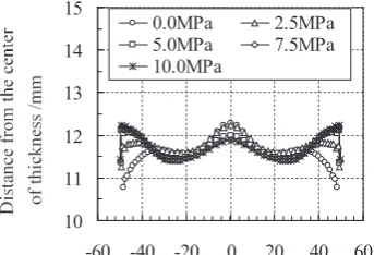
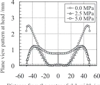
3.2 Effect of back pressure on slab head end shape To confirm the accuracy of the analysis, the deformation behavior of the slab head end when back pressures from 0.0 to 10.0 MPa were applied in full-length width reduction was investigated by using the developed FEM model. Figure 7 shows the changes in the slab thickness profile and plan-view pattern depending on the magnitude of back pressure. With width reduction of both ⊿w = 20 and 40 mm, the plan-view pattern of the slab head end changed from the fish-tail shape to the tongue shape when back pressure was applied. In the thickness profile, the amount of local thickness increase in the slab width center decreased and the slab edge thickness
Fig. 7 Influence of back pressure on slab head shape after width reduction of (a), (c) 20 mm and (b), (d) 40 mm.
[image:4.595.323.516.47.738.2] [image:4.595.336.508.85.202.2]increased. In particular, under the conditions of back pressure of 5.0 MPa and ⊿w = 40 mm, the maximum thickness de-creased and the slab also approached a flat slab thickness pro-file. From this, improvement of biting performance in hori-zontal rolling and stability in slab conveying can be expected. However, at back pressures of 7.5 MPa and higher, the effect on the plan-view pattern was limited.
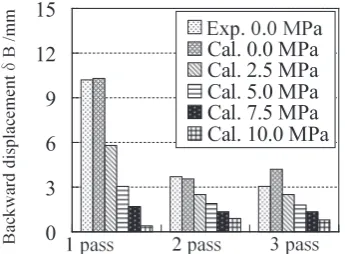
The backward displacement of the slab δB in passes 1-3 with ⊿w = 40 mm is shown in Fig. 8. Under the no back pressure condition, the experimental and FEM results showed good agreement. In comparison with the no back pressure condition, δB was suppressed by back pressure, especially in the 1st pass. Regarding the effect of the magnitude of back
pressure, δB decreased greatly as back pressure increased from 2.5 to 5.0 MPa, but the decrease in δB with increasing back pressure was small at 7.5 and 10.0 MPa. In other words, the fact that the change in the head end shape shown in Fig. 7 became small at back pressures of 7.5 MPa and higher is con-sidered to be because the applied back pressure was suffi-ciently large, and as a result, the change in the amount of re-duction of slab backward displacement δB became slight.
3.3 Effect of number of back-pressure passes on head end shape
The effect of the number of passes in which back-pressure was applied on the slab head end shape is shown Fig. 9(a) and (b). These results are all analytical results and were calculated under the constant conditions of ⊿w = 40 mm and back pres-sure of 5.0 MPa. Five conditions were used for the number of back pressure passes, these being 0 (no back pressure), 1, 1-2, 1-3 and 1-4. Here, 1-2 pass means that back pressure was applied in both passes 1 and 2; similarly, 1-3 and 1-4 mean that back pressure was applied from pass 1 to pass 3 or pass 4, respectively. Under the condition of back pressure in only the 1st pass, the plan-view pattern changed from the fishtail
shape to the tongue shape, and the local increase in thickness at the slab width center decreased. However, back pressure in the 2nd pass and subsequent passes had only a limited effect
on the slab head shape. This result is thought to be due to the large decrease in backward displacement in the 1st pass shown
in Fig. 8. These results also show that it is necessary to per-form width reduction at the slab head end with the inclined part of the dies in order to control the slab head end shape by back pressure.
4. Discussion
4.1 Strain distribution after width reduction and mech-anism of local thickness increase at width center The effect of back pressure during width reduction on the strain distribution of the slab head end was investigated in order to clarify the deformation mechanism in changes in the shape of the slab head end. Using the FEM results, the results without back pressure and with back pressure of 5.0 MPa over the full length were compared. An evaluation of equiva-lent plastic strain was performed. The measurement positions were from the slab head to 80 mm in the slab tail direction for the center of slab width and thickness, and the full width at the center of slab thickness position at the slab head. The re-sults of these measurements are shown in Fig. 10(a) and (b). At the head end, the amount of equivalent plastic strain at the center of slab width and thickness, which is shown in Fig. 10(a), was reduced by application of back pressure. Thereafter, the value became approximately the same as that under the condition of no back pressure. The distribution of equivalent plastic strain in the width direction of the slab head part, shown in Fig. 10(b), was reduced at the width center and increased at the edges as a result of application of back pres-sure. From these results, it is considered that back pressure has the effect of homogenizing strain in the width and longi-tudinal directions at the slab head. As a result, the local thick-ness increase in the width center at the slab head is sup-pressed.
Next, the mechanism of the local thickness increase in the Fig. 8 Influence of back pressure on backward displacement at tail end of
slab after width reduction of 40 mm.
[image:5.595.82.255.70.197.2] [image:5.595.337.504.71.190.2] [image:5.595.332.517.88.381.2]width center at the slab head will be discussed. This local in-cerase is particularly a problem under large width reduction conditions. Figure 11 shows a schematic illustration of the deformation during width reduction of the slab head end part in the 1st pass and the forces acting on the slab at that time. As
shown in Fig. 11, because the 1st width reduction pass is
per-formed with the inclined part of the dies, a backward compo-nent force Psinθ corresponding to the angle of die inclination
θ relative to the width reduction force P is generated in the slab. On the other hand, a width reduction force P and a fric-tion force μPcosθ, which is due to the friction coefficient μ
between the dies and the slab, are generated at the area of contact between the dies and the slab, and these forces act on the backward component force Psinθ. That is, displacement of the slab edges is restrained by friction force. Because de-formation corresponding to the width reduction force and backward component force occurs in the part which is not in
contact with the dies, the slab is displaced backward simulta-neously with width reduction. As a result, the fish-tail shape is built into the plan-view pattern at the slab head. In the 2nd
width reduction pass, no material exists in the center of slab width at the front end of the slab because the fish-tail shape was already built into the slab during the 1st pass. For this
reason, it is considered that the strain during width reduction is not homogenized in the slab width direction, deformation such as bending occurs in the width direction, and a local thickness increase occurs because strain concentrates in the center of the slab width. Application of back pressure against the backward displacement of the slab acts on the backward component force during width reduction, which is the cause of the local thickness increase and fishtail shape of the slab head, and thus is effective for controlling these shapes.
4.2 Width reduction experiment using lead slabs with mechanically-worked head end parts
A local thickness increase occurs around the width center of the slab head end due to width reduction. The fish-tail shape which is built into slabs in the 1st pass is estimated to be
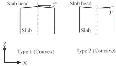
the cause of this thickness increase. That is, if the fish-tail shape during width reduction is remarkable, the thickness in-crease in the widthwise center will be large, and conversely, if the fish-tail shape is small, the amount of this thickness in-crease should dein-crease. In order to clarify the effect of the initial shape of the slab head on the slab head shape after width reduction, the head ends of lead slabs were machined to produce slabs with a fish-tail shape or tongue shape as the initial shape, and the deformation behavior of the slab head was investigated. The plan-view patterns of these preformed lead slabs are shown in Fig. 12. The width and thickness are the same as in Fig. 2. As the initial shapes, angles were given from the center of the slab width as the origin to the slab edg-es so as to form an initial linear convex or concave shape. The angle was determined to be 3 based on the plan-view pattern of the slab head in 1st pass width reduction without back
pres-sure. A convex shape in the rolling direction was defined as Type 1, and a concave shape was defined as Type 2. Full-length width reduction of the slabs prepared in this manner was performed with width reduction of 40 mm. The other conditions were the same as in Table 1. Figures 13 and 14 show the plan-view pattern and thickness profile of the slab head after width reduction. The FEM results for the analysis condition in which the initial plan-view pattern of the slab head was rectangular are also plotted in the figures.
From these results, when the initial shape is a fish-tail Fig. 10 Distribution of equivalent plastic strain. (a) εeq of thickness and
width center of the slab, (b) εeq in the width direction at slab head.
Fig. 11 Schematic of force equilibrium in 1st pass of width reduction by
sizing press.
[image:6.595.83.244.59.367.2] [image:6.595.330.520.69.178.2] [image:6.595.84.253.417.531.2]shape, the fish-tail is encouraged by width reduction, and ac-companying this, the local thickness increase of the slab width center becomes larger. Conversely, if the initial shape is a tongue shape, the fish-tail shape after width reduction is suppressed, and this results in a decrease in the thickness in-crease. From these experiments as well, suppressing the fish-tail shape during width reduction by applying back pressure is considered to be effective for suppressing the local thick-ness increase in the width center part of the slab head.
4.3 Technique for control of slab head end shape after horizontal rolling by back pressure control
The plan-view pattern of the slab head end after rolling by the horizontal rolling mill, which is installed at the delivery side of the sizing press, is important when considering reduc-tion of the amount of crop loss in an industrial operareduc-tion. As mentioned previously, the slab head shape after horizontal rolling is determined mainly by the thickness profile and plan-view pattern of the slab head end after width reduction. Therefore, the plan-view pattern of the slab head end after horizontal rolling to the initial thickness when back pressure was applied in the 1st pass was investigated under the
condi-tion of ⊿w = 20 mm, considering the fact that the 1st pass has
a large effect in head end shape control. Two conditions were used for the magnitude of back pressure, namely, 2.5 and 5.0 MPa. Figure 15 shows a comparison of the plan-view
pat-tern of the slab head end after horizontal rolling with these back pressure conditions and a condition of no back pressure. The plan-view pattern of the slab head after horizontal rolling was changed from the fish-tail shape to the tongue shape by application of back pressure. Furthermore, when back pres-sure of 2.5 MPa was applied, the crop loss length was short in comparison with the condition of no back pressure. In terms of area, back pressure of 2.5 MPa resulted in a crop loss re-duction effect of approximately 50%. These results suggested the possibility that the yield can be improved by applying ap-propriate back pressure corresponding to the slab width and amount of width reduction during width reduction by the siz-ing press.
5. Conclusion
The effect of applying back pressure of 0.0–5.0 MPa in the rolling direction to the slab tail end by the sizing press on the slab head end shape was investigated by FEM. The slab size was 120 mm in width and 21 mm in thickness, and the width reduction by the sizing press was ⊿w = 20 mm or 40 mm. The following conclusions were obtained.
(1) Application of back pressure during width reduction reduced the amount of thickness increase in the width center of the slab head end and increased the thickness increase at the slab edges after width reduction. In addition, the plan-view shape changed from a fish-tail shape to a tongue shape.
(2) Application of back pressure reduces the backward dis-placement δB of the slab which occurs during width reduc-tion, particularly in the 1st pass. However, at back pressures of
5.0 MPa and higher, the magnitude of back pressure had little effect on δB, and as a result, the effect on the slab head end shape was also limited. In other words, when performing con-trol of the head end shape by back pressure, back-pressure control which can sufficiently reduce δB is considered neces-sary in the 1st pass, in which width reduction is performed
with the inclined part of the sizing press dies.
(3) An analysis of the slab strain distribution after width reduction with/without back pressure during width reduction was performed. When back pressure was not applied, it was found that the strain in the width direction in the 2nd and later
passes is concentrated in the center of slab width due to the fish-tail shape which was built into the slab by backward dis-placement in the 1st pass, and this results in a local thickness
Fig. 13 Influence of slab head shape on plan view pattern after width reduc-tion of 40 mm.
[image:7.595.76.263.70.218.2]Fig. 15 Influence of back pressure on plan view pattern after horizontal rolling.
[image:7.595.342.503.72.208.2] [image:7.595.66.268.273.412.2]increase in the slab width center. In contrast, when back pres-sure is applied, suppression of δB in the 1st pass results in a
uniform strain distribution in the width direction in the 2nd
pass and thereafter, and the local thickness increase in the width center is suppressed.
(4) Under the condition of ⊿w = 20 mm, the fish-tail shape after horizontal rolling is suppressed by applying back pres-sure of 2.5 MPa in the 1st pass, when shape controllability is
large. The possibility that the amount of crop loss can be re-duced by approximately 50% under these conditions was sug-gested. Finally, although experimental verification is neces-sary, application of appropriate back pressure during head end width reduction is also considered to have the potential to reduce crop loss under other rolling conditions.
REFERENCES
1) K. Mori and K. Osakada: Journal of the Japan Society for Technology of Plasticity. 23-260 (1982). 897–902.
2) H. Nikaido, K. Fujiwara, H. Abe and M. Nihei: Iron Steel Eng. 21
(1984) 48–53.
3) S. Takizawa, T. Naoi, A. Harimoto, H. Nikaido and T. Kondo: Tetsu- to-Hagané 74-7 (1988) 142–149.
4) T. Naoi, K. Fujiwara, T. Nakanishi, M. Nihei and S. Nishimura: Hitachi Review. 30-3 (1990) 193–198.
5) H. Abe: Journal of the Japan Society for Technology of Plasticity. 25-277 (1984). 87–92.
6) N. Tazoe, K. Ide, H. Dazai, M. Koike and C. Mochizuki: Ishikawaji-ma-Harima Engineering Review. 30-3 (1990) 193–198.
7) R.M. Forouzan, I. Salehi and H.A. Adibi-sedeh: J. Mater. Process. Technol. 209 (2009) 728–736.
8) T. Hira, K. Isobe, H. Abe, H. Nikaido, T. Fujitsu and S. Zuyama: Kawa-saki Steel Giho 21-3 (1989) 188–194.
9) K. Isobe, T. Hira and H. Abe: Journal of the Japan Society for Technol-ogy of Plasticity. 30-340 (1989). 682–688.
10) T. Fujitsu, T. Fujimoto, H. Nikaido and M. Nihei: Steel Times Interna-tional 217 (1989) 266–270.
11) H. Muller and W. Rohde: Metallurgical Plant and Technology Interna-tional 5 (1992) 60–69.