Effect of Lamination Constitution on Post-Buckling Behavior of Symmetrically
Laminated Plates with Initial Deflections
*1Keiichi Nemoto
1, Hisao Kikugawa
2,*2, Hiroyuki Moriyama
3and Hirakazu Kasuya
4 1Department of Aerospace Engineering, The Yokohama Rubber Co.,Ltd., Hiratsuka 254–8601, Japan2Department of Biomedical Engineering, School of Engineering, Tokai University, Hiratsuka 259–1292, Japan 3Department of Prime Mover Engineering, School of Engineering, Tokai University, Hiratsuka 259–1292, Japan 4Professor Emeritus of Tokai University, Hiratsuka 259–1292, Japan
Advanced fiber-reinforced composite materials are being used as structural members in various fields because of their high strength and high stiffness-to-weight ratios. Hence, analysis of thin laminated structures is important. The post-buckling behaviors of thin laminated plates under uniaxial compression have been discussed by many researchers. However, little research has been performed on the secondary buckling phenomenon for thin laminated plates, which occurs with further increase of load. In this paper, the stability conditions of carbon–epoxy sym-metrically laminated plates with initial deflections under uniaxial compression that are simply supported along four edges are determined using the second variation of total potential energy. The necessity of secondary buckling is proven analytically, and the effects of various factors, such as initial deflection, lamination constitution, and number of layers, are elucidated. [doi:10.2320/matertrans.M2016015]
(Received January 14, 2016; Accepted February 17, 2016; Published April 25, 2016)
Keywords: structural analysis, composite materials, carbon fiber reinforced plastic (CFRP), secondary buckling, initial deflection, symmetri-cally laminated plates
1. Introduction
The use of advanced composite materials, such as carbon fiber reinforced plastics, has been rapidly expanding to a wide range of industrial applications because they have excellent properties such as high specific strength and specific stiffness. Composite structures are used in aircraft-wings for the effect of coupling due to bending deformation and twisting defor-mation. In general, symmetrically balanced laminates reduce buckling load for most applications owing to coupling ef-fects1–3).
Symmetrically balanced laminates not experience in-plane extension–shear coupling owing to their extensional stiffness, A16 and A26; however, they do experience out-of-plane bend-ing–twisting coupling because of their bending stiffness, D16 and D26. By introducing the non-dimensional anisotropic pa-rameter for a finite number of layers, Nemeth4) proved that lamination constitutions capable of ignoring the effect of the bending–twisting coupling terms, D16 and D26, result in com-pression buckling. Furthermore, Terada, Todoroki, and Shi-mamura5) neglected D
16 and D26 while analyzing the optimal design of symmetrically laminated plates while neglecting subjected to compressions.
Numerous researchers have discussed the post-buckling behavior of thin symmetrically laminated plates under in-plane compression6). However, the equilibrium state after pri-mary buckling is not stable under continually increasing com-pression, and the structure reconfigures to another equilibrium state of higher order. Uemura and Byon7) studied the second-ary buckling phenomenon, which occurs with further increas-es in load, for thin isotropic platincreas-es. We previously reported the secondary buckling of orthotropic laminated plates8–10), but the secondary phenomenon of symmetrically balanced
laminates with initial deflection under compression are still unknown.
In this paper, we examine the buckling problems of sym-metrically laminated square plates with initial deflections that are subjected to axial compression, and we expand the pro-posed analytical techniques from the previous paper10). The stability of the post-buckling equilibrium states can be dis-cussed using the second variation in the total potential energy. Additionally, the occurrence of secondary buckling was prov-en analytically, and the effects of various factors, especially lamination constitutions4), are discussed.
2. Buckling Analysis Method
2.1 Fundamental equations of symmetrically laminated
plates
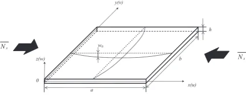
Figure 1 shows the coordinate system and dimensions of the laminated plates with initial deflection under uniaxial compression Nx. The width and length are given by a and b;
the thickness is h; the terms u, v, and w denote the displace-ment components relative to the center in the x, y, and z direc-tions, respectively; the term w0 denotes the initial deflection. The in-plane nonlinear strain components εx, εy, and γxy and
the changes in curvatures κx, κy, and κxy can be written in
terms of the displacement components:
*1
This Paper was Originally Published in Japanese in J. Japan Inst. Met. Mater. 79 (2015) 49–56.
*2
Corresponding author, E-mail: [email protected]
Fig. 1 Configuration and coordinates of symmetrically laminated plate with small initial deflection under uniaxial compression.
[image:1.595.306.547.670.763.2]εx= ∂u ∂x+ 1 2 ∂w ∂x 2 + ∂w ∂x ∂w0 ∂x ,
εy=∂v ∂y+ 1 2 ∂w ∂y 2 + ∂w ∂y ∂w0 ∂y ,
γxy= ∂u ∂y+ ∂v ∂x+ ∂w ∂x ∂w ∂y + ∂w ∂x ∂w0 ∂y
+ ∂w0
∂x ∂w ∂y , (1)
κx=−∂ 2w
∂x2, κy=− ∂2w
∂y2, κxy=−2 ∂2w
∂x∂y. (2)
The axial, circumferential, and shear strains of the median surface are given in terms of the median surface stresses from the usual form of Hooke s law for thin plates:
εx=σx/E−υσy/E, εy=σy/E−υσx/E, γxy=τxy/G.
(3)
In this paper, we treat the isotropic modulus in-plane with the composite laminated plates. Therefore, E (Ex = Ey) is the modulus of elasticity, υ (υx = υy) is Poisson s ratios, and G (= Gxy) is the shear modulus. The membrane forces per unit width Nx, Ny, and Nxy are defined as,
Nx=
h/2
−h/2
σxdz= Eh 1−υ2
∂u ∂x+ 1 2 ∂w ∂x 2 + ∂w ∂x ∂w0 ∂x
+υ ∂v
∂y+ 1 2 ∂w ∂y 2 + ∂w ∂y ∂w0 ∂y ,
Ny=
h/2
−h/2
σydz= Eh 1−υ2
∂v ∂y+ 1 2 ∂w ∂y 2 + ∂w ∂y ∂w0 ∂y
+υ ∂u
∂x+ 1 2 ∂w ∂x 2 + ∂w ∂x ∂w0 ∂x ,
Nxy=
h/2
−h/2
τxydz=Gh ∂u ∂y + ∂v ∂x+ ∂w ∂x ∂w ∂y + ∂w ∂x ∂w0 ∂y + ∂w0 ∂x ∂w ∂y . (4) In this paper, the membrane force and bending moment re-sultants for symmetrically balanced laminates at the middle surface are, Nx Ny Nxy =
A11 A12 0 A12 A11 0 0 0 A66
εx εy γxy , Mx My Mxy =
D11 D12 D16 D12 D22 D26 D16 D26 D66
κx κy κxy , (5)
where Aij (i, j = 1, 2, 6) is the extensional stiffness and Dij (i, j = 1, 2, 6) is the bending stiffness of the laminated plate. Thus, we can calculate the material constants EL, ET, υL, υT, GLT, of the unidirectional composites and the lamination
an-gle θ11). Subscripts L and T denote the longitudinal and trans-verse directions, respectively, of the fiber.
However, post-buckling analyses of thin plates considering bending–twisting coupling via D16 and D26 are very difficult. The effect of the bending–twisting coupling can be ignored when the anisotropic parameters γ and δ are smaller than 0.24):
r= D16 4D3
11D22
, δ= D26 4D
11D322
(6)
The energy Um due to the strain in the middle of the plate
and the energy Ub due to bending are, respectively,
Um=1 2
a
0 b
0
(Nxεx+Nyεy+Nxyγxy)dxdy, (7)
Ub=12 a
0 b
0
(Mxκx+Myκy+Mxyκxy)dxdy. (8)
The total strain energy is the summation of the energy due to bending and energy due to the strain in the middle of plate:
Π =Um+Ub. (9)
By introducing eqs. (3), (5), (6), and (7) into eq. (8), we ob-tain,
Π = 1
2 a 0 b 0 1 h
Nx2
E −
2υ E NxNy+
Ny2
E +
Nxy2
G
+ D11 ∂ 2w
∂x2 2
+2D12∂ 2w
∂x2 ∂2w
∂y2
+D22 ∂ 2w
∂y2 2
+4D66 ∂ 2w
∂x∂y
2
dxdy. (10)
2.2 Equilibrium and compatibility equations
The equilibrium equations in the x, y, and z directions of a laminated plate are expressed as,
∂Nx ∂x +
∂Nxy ∂y =0, ∂Nxy
∂x + ∂Ny
∂y =0, (11)
D11∂ 4w
∂x4 +2(D12+2D66) ∂4w ∂x2∂y2 +D22
∂4w ∂y4
=Nx ∂ 2(w+w
0) ∂x2 +Ny
∂2(w+w0) ∂y2
+2Nxy ∂
2(w+w 0)
∂x∂y . (12)
The Airy function F, which satisfies eq. (11), is defined by,
Nx=h∂
2F
∂y2, Ny=h ∂2F
∂x2, Nxy=−h ∂2F
∂x∂y, (13) and reduces eq. (12) to the form,
D11∂ 4w
∂x4 +2(D12+2D66) ∂4w ∂x2∂y2 +D22
=h ∂ 2F
∂y2
∂2(w+w0) ∂x2 +
∂2F ∂x2
∂2(w+w0) ∂y2
−2∂2F
∂x∂y
∂2(w+w0)
∂x∂y . (14)
By eliminating u and v from eq. (1), the compatibility equation is obtained:
H11 ∂ 4F
∂x4 + ∂4F
∂y4 +2(H12+H66) ∂4F ∂x2∂y2
= 1 h
∂
2w
∂x∂y
2
−∂∂2xw2 ∂∂2yw2
, (15)
where,
H11=A11A66/H, H12=−A12A66/H
H66=(A112−A122)/H, H=A112A66−A122A66. (16)
The average axial strain in the x-direction, εmx, in the
mid-dle of the plane is defined by using by H11 and H12 in eq. (16):
εmx=−1a a
0 ∂u ∂xdx
=−1 a
a
0
hH11∂
2F
∂y2 +hH12 ∂2F
∂x2 −
1 2
∂w ∂x
2
dx. (17)
The post-buckling behavior can then be studied through the solution of the nonlinear simultaneous equilibrium and compatibility equations involving stress function F and de-flection w under the given boundary conditions. Approximate solutions of these equations will be sought because obtaining the exact solution is very difficult.
2.3 Analysis of post-buckling behavior
The simply supported out-of-plane boundary conditions are
w=∂ 2w
∂x2 =0 at x=0,a,
w=∂ 2w
∂y2 =0 at y=0,b,
(18)
and the in-plane conditions are expressed as follows: u=constant along y-axis at x=0,a,
b
0
Nxdy=−Nxb, Nxy=0,
v=constant along x-axis at y=0,b,
a
0
Nydx=0, Nxy=0.
(19)
Here, w and w0 are expressed by terms that correspond to symmetrical and asymmetrical modes, respectively, along the loading axis:
w=w11sin πax sin πby +w21sin 2aπx sin πby ,
w0=c11sin πax sin πby +c21sin 2aπx sin πby ,
(20)
where w11 is the half-wave number of the buckling half-wave in the x- and y-directions, and w21 is the wave number of the
buckling half-wave in the x-direction and the half-wave num-ber of the buckling half-wave in the y direction; c11 and c21 represent the amplitude of the initial deflection. Substituting eq. (20) into the right-hand side of eq. (15) yields:
F= 1
2hλ2(w11 2+2w
11c11)
× 16Hλ4 11 cos
2πx
a +
1 16H11cos
2πy b
+ 2
hλ2(w212+2w21c21)
× 256Hλ4 11cos
4πx
a +
1 16H11 cos
2πy b
−4h1λ2(w11w21+w11c21+w21c11)
× Hλ4 11
1 9cos
3πx a −cos
πy a
−81H λ4cos(3πx/a) cos(2πy/b) 11+36(2H12+H66)λ2+16H11λ4
+ λ
49 cos(πx/a) cos(2πy/b)
H11+4(2H12+H66)λ2+16H11λ4 − σxy2
2 ,(21)
where λ = a/b.
When we substitute the deflection w and stress function F in the equilibrium equation in the lateral deflection, i.e., as in eq. (12), the following simultaneous equation is obtained by applying the Galerkin method. Then, w11 and w21 are deter-mined by applying the Newton–Raphson method9). We obtain the relationship between the average axial compressive stress σx and the average shortening of the middle surface of the
laminated plates εmx:
εmx=−1a a
0 ∂u ∂x dx
=−1 a
a
0
εx−12 ∂
w ∂x
2
−∂∂wx∂∂wx0 dx
=H11σxh+π
2
8a2(w112+2w11c11+4w212+8w21c21). (22)
2.4 Stability criterion of post-buckling
The equilibrium equations can be obtained by equating the first variation δΠ of the total potential energy Π to zero, i.e., by the stationary potential energy. The stability of the equilib-rium state can be discussed by the following second variation δ2Π:
δ2Π =1
2 a
0
b
0
1 h
δNx2
E +
δNy2
E −
2υ
EδNxδNy+ δNxy2
G
+ Nx ∂δw
∂x
2
+Ny ∂δw
∂y
2
+2Nxy∂δw
∂x ∂δw
∂y
+ D11 ∂ 2δw
∂x2 2
+2D12∂ 2δw
∂x2 ∂2δw
∂y2
+D22 ∂ 2δw
∂y2 2
+4D66 ∂ 2δw
∂x∂y
2
where,
δNx= 1Eh
−υ2 ∂δu
∂x + ∂w ∂x
∂δw ∂x +
∂w0 ∂x
∂δw ∂x
+υ ∂δv ∂y +
∂w ∂y
∂δw ∂y +
∂w0 ∂y
∂δw ∂y ,
δNy=1Eh
−υ2 ∂δv
∂y + ∂w
∂y ∂δw
∂y + ∂w0
∂y ∂δw
∂y
+υ ∂δu ∂x +
∂w ∂x
∂δw ∂x +
∂w0 ∂x
∂δw ∂x ,
δNxy=Gh ∂δv
∂x + ∂δu
∂y + ∂δw
∂x ∂w ∂y +
∂w ∂x
∂δw ∂y
+ ∂w0 ∂x
∂δw ∂y +
∂δw ∂x
∂w0 ∂y .
(24)
If δ2Π is positive, the equilibrium state is stable; if it is zero, the equilibrium state is neutral; if it is negative, the equi-librium state is unstable. The assumed virtual displacement poses a problem because the sign of δ2Π cannot be judged independently of the assumed patterns. In this study, a meth-od is proposed to set the appropriate virtual displacements. That is, the variation in δ2Π with respect to δu, δv, and δw is considered essential for obtaining the extremum of δ2Π under the given boundary conditions for a set of assumed virtual displacements. The following equilibrium equations for vir-tual displacements are obtained:
∂δNx
∂x +
∂δNxy
∂y =0,
∂δNxy
∂x +
∂δNy
∂y =0,
(25)
D11∂ 4δw
∂x4 +2(D12+2D66) ∂4δw
∂x2∂y2 +D22 ∂4δw
∂y4
=δNx ∂
2(w+w 0)
∂x2 +2δNxy
∂2(w+w0) ∂x∂y
+δNy ∂
2(w+w 0) ∂y2 +Nx
∂2δw
∂x2
+2Nxy∂
2δw
∂x∂y+Ny
∂2δw
∂y2 . (26)
The virtual stress function δF that satisfies eqs. (25) is,
δNx=h∂
2δF
∂y2 , δNy=h ∂2δF
∂x2 , δNxy =−h ∂2δF
∂x∂y. (27) If we then eliminate δu and δv from eq. (24), the following compatibility equation for virtual displacements is obtained:
H11∂ 4δF
∂x4 +(2H12+H66) ∂4δF
∂x2∂y2 +H11 ∂4δF
∂y4
= 1 h 2
∂2w
∂x∂y
∂2δw
∂x∂y −
∂2w
∂x2 ∂2δw
∂y2 − ∂2δw
∂x2 ∂2w
∂y2
+2∂
2w 0 ∂x∂y
∂2δw
∂x∂y−
∂2w0 ∂x2
∂2δw
∂y2 − ∂2δw
∂x2 ∂2w0
∂y2 . (28)
The boundary conditions for the virtual displacements δu, δv, and δw and the virtual membrane forces δNxy are
δu=0, δNxy=0, δw= ∂
2δw
∂x2 =0 at x=0,a,
δv=0, δNxy=0, δw=∂
2δw
∂y2 =0 at y=0,b, (29)
and, for the simply supported condition, δw is assumed to be:
δw=δwpqsin paπxsinqπby, (30)
where p and q are positive integers. This corresponds to the predominant deflected mode of the post-buckled state, which is excluded because it does not satisfy δu or δv in eq. (29). Substituting w and δw of eqs. (20) and (30), respectively, into eq. (28), δF is determined so as to satisfy eq. (29):
δF= λ
2
4hδwpq(w11+c11)
×
−
cos (1+p)
a πx cos
(1+q)
b πy (p−q)
2
H11(1+p)4+λ2(2H12+H66)(1+p)2(1+q)2+λ4H11(1+q)4
+
cos (1+p)
a πx cos
(1−q)
b πy (p+q)
2
H11(1+p)4+λ2(2H12+H66)(1+p)2(1−q)2+λ4H11(1−q)4
+
cos (1−p)
a πx cos
(1+q)
b πy (p+q)2 H11(1−p)4+λ2(2H12+H66)(1−p)2(1+q)2+λ4H11(1+q)4
−
cos (1−p)
a πx cos
(1−q)
b πy (p−q)
2
H11(1−p)4+λ2(2H12+H66)(1−p)2(1−q)2+λ4H11(1−q)4 +λ 2
4hδwpq(w21+c21)
×
−
cos (2+p)
a πx cos
(1+q)
b πy (p−2q)
2
H11(2+p)4+λ2(2H12+H66)(2+p)2(1+q)2+λ4H11(1+q)4
+
cos (2+p)
a πx cos
(1−q)
b πy (p+2q)
2
H11(2+p)4+λ2(2H12+H66)(2+p)2(1−q)2+λ4H11(1−q)4
+
cos (2−p)
a πx cos
(1+q)
b πy (p+2q)2 H11(2−p)4+λ2(2H
12+H66)(2−p)2(1+q)2+λ4H11(1+q)4
−
cos (2−p)
a πx cos
(1−q)
b πy (p−2q)
2
H11(2−p)4+λ2(2H12+H66)(2−p)2(1−q)2+λ4H11(1−q)4 , (31) where membrane forces Nx, Ny, and Nxy are determined by
3. Numerical Results and Discussion
The solution method outlined above was applied to investi-gate the secondary buckling behavior of symmetrically lami-nated plates. The elastic constants of unidirectional carbon fiber–reinforced epoxy composites having fiber volume con-tents of Vf = 60%, which were obtained using the approximate
average method, were confirmed by experiments12) and are as follows:
EL=137 (GPa), ET =8.17 (GPa), GLT =4.75 (GPa), υL=0.316, υT =0.0189.
(32) The relationship between the non-dimensional average ax-ial compression K = Nxb2/π 2√D11D22 and the average axial
strain in the x-direction εmx of the symmetrically laminated
square plates (λ = 1) without initial deflections is shown in Fig. 2. Figures 2(a) and (b) show results for lamination con-stitutions [±45/0/90] and [0/90/±45], respectively. The number of layers N = 8 case is shown by the solid line; the number of layers N = 24 case is shown by the dash-dot line; the number of layers N = 48 case is shown by the
dash-dot-dot line. In these figures, Kp is the primary buckling value,
and Ks is the secondary buckling value. The numbers in the
parentheses represent the number of primary buckling half-waves (i.e., secondary buckling three-half-half-waves) in the x- di-rections and the number of primary buckling half-waves (i.e., secondary buckling two-half-waves) in the y-directions.
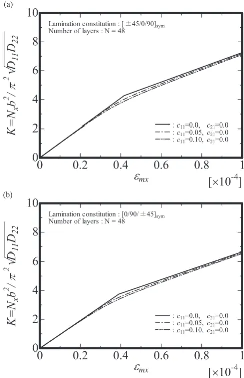
The relationship between the non-dimensional average ax-ial compression K and average axax-ial strain of the x-axis direc-tion εmx of the symmetrically laminated square plates (λ = 1)
with initial deflections is shown in Fig. 3. Figures 3(a) and (b) show results for the lamination constitutions [±45/0/90] and [0/90/±45], respectively, and include the corresponding number of layers N = 48 case results. Results for c11 = 0.0 and c21 = 0.0 are shown by the solid line; results for c11 = 0.05 and c21 = 0.0 are shown by the dash-dot line; results for c11 = 0.10 and c21 = 0.0 are shown by the dash-dot-dot line. Again, c11 and c21 are the initial deflection amplitudes of the symmetri-cal and asymmetrisymmetri-cal modes, respectively, based on eq. (20). Furthermore, c11 = 0.1, which is the half-wave in the-x direc-tion and the half-wave in the y-direcdirec-tion, indicates that the magnitude is 10% of the plate thickness.
The relationship between the non-dimensional average
ax-Fig. 2 The relationship between axial compressive stress K and average axial shortening εmx without initial deflection at number of layers N = 8, 24 and 48.
(a) Lamination constitution [±45/0/90], (b) Lamination constitution [0/90/±45].
Fig. 3 The relationship between axial compressive stress and average axial shortening with initial deflection c11 = 0.0, 0.05 and 0.10 at number of
layers N = 48.
[image:5.595.303.547.355.732.2] [image:5.595.48.293.355.734.2]ial compression K and the number of plies 8 M of the sym-metrically laminated square plates with and without initial deflections is shown in Fig. 4. For numbers of plies ranging from 8 to 48, Figs. 4(a) and (b) show results for the case of c11 = 0.0 and c21 = 0.0 (i.e., without initial deflection10)) and c11 = 0.10 and c21 = 0.00, respectively. The secondary buck-ling values for the isotropic plates8) are K
S = 25.99 and KS =
26.04 in Figs. 4(a) and (b), respectively.
Table 1 lists the variation of the secondary buckling stress-es for symmetrically laminated platstress-es with initial deflections of c11 = 0.0, 0.05, and 0.10 under compression. The analytical method indicates that the second variation of the total poten-tial energy δ2Π strongly depends on the number of half-waves p and q in the virtual displacement; the minimum values are then the secondary buckling stresses.
Tables 2 and 3 list the secondary buckling stresses and number of half-waves of virtual displacements p and q for lamination constitutions [±45/0/90] and [0/90/±45], respec-tively, for 8, 16, 24, 32, 40, or 48 layers, with initial deflec-tions of c11 = 0.0, 0.05, and 0.10 and c21 = 0.0, 0.05, and 0.10. As shown in Table 2 and 3, for all lamination constitutions,
w11 governs the conditions regarding the deflection pattern of post-buckling. The half-wave numbers of the primary
buck-ling in the x- and y-direction are determined. Thus, in this case, w21 is ignored. As seen in the tables, minimum values of Ks are obtained when virtual displacements are considered
regardless of the amplitude of the initial deflection.
From these results, it is clear that the post-buckled equilib-rium state with small-wave modes p and q (in both the x- and
y-directions) cannot be proven unstable using only a virtual displacement. However, it can be proven that the post-buck-led equilibrium state becomes unstable when virtual displace-ments p and q are considered and the inevitable secondary buckling is given analytically.
As shown in Figs. 2 and 3, the secondary buckling stress was several times that of the primary buckling stress; the stresses were obtained for the load-carrying capacity of thin laminated plates after primary buckling. The curves in Figs. 2 and 3 become straight lines with slopes equal to those prior to buckling. After primary buckling, the slopes of these lines may decrease. This indicates a loss of stiffness in the
Fig. 4 The relationship between non-dimensional secondary buckling stresses K and number of plies, 8 M at initial deflection c11 = 0.00 and
0.10.
[image:6.595.50.293.68.443.2](a) c11 = 0.00, c21 = 0.00, (b) c11 = 0.10, c21 = 0.00.
Table 1 Variation of secondary buckling stresses with various deflection patterns at number of layers N = 48, lamination constitution [0/90/±45].
q c11 c21 p
1 2 3 4
1
0.00 0.00 ̶
Stable Stable Stable
0.05 0.00 Stable Stable Stable
0.10 0.00 Stable Stable Stable
2
0.00 0.00 Stable 34.97 25.01 29.44
0.05 0.00 Stable 35.05 25.03 29.45
0.10 0.00 Stable 35.14 25.06 29.46
3
0.00 0.00 Stable 139.64 50.59 46.06
0.05 0.00 Stable 139.71 50.61 46.07
[image:6.595.306.550.95.235.2]0.10 0.00 Stable 139.79 50.93 46.08
Table 2 Secondary buckling stresses of symmetrically laminated plates with variation of amplitude of initial deflection, and number of layers at lamination constitution [±45/0/90].
Lamination
constitution Number of layers c11 c21 p q Ks
[±45/0/90]sym
8
0.00 0.00 3 2 38.50 0.05 0.00 3 2 38.54 0.10 0.00 3 2 38.58
16
0.00 0.00 3 2 31.85 0.05 0.00 3 2 31.88 0.10 0.00 3 2 31.91
24
0.00 0.00 3 2 29.80 0.05 0.00 3 2 29.83 0.10 0.00 3 2 29.86
32
0.00 0.00 3 2 28.82 0.05 0.00 3 2 28.84 0.10 0.00 3 2 28.88
40
0.00 0.00 3 2 28.23 0.05 0.00 3 2 28.26 0.10 0.00 3 2 28.29
48
[image:6.595.307.549.295.547.2]post-buckling range that is greatly dependent on the number of half-waves of the virtual displacements p and q.
As shown in Fig. 4, the secondary buckling values Ks for the balanced laminated plates are different owing to the stack-ing sequence. Because the flexible stiffness Dij differs be-tween the lamination constitutions [±45/0/90] and [0/90/±45], these stiffness values affect the secondary buck-ling. The secondary buckling values Ks also approach that of the isotropic material as the number of layers increases.
As shown in Tables 2 and 3, the number of half-waves of the virtual displacements p and q perfectly agree for all num-bers of layers. There was little change in the secondary buck-ling stress within the ranges of initial deflection amplitudes
considered here. In addition, the secondary buckling stresses were mostly unaffected by the presence of any initial deflec-tion, and the secondary buckling Ks increased only slightly as the amplitude of the initial deflection increased. In addition, the secondary buckling values Ks decrease significantly when
the lamination constitution [0/90/±45] was 8 plies.
4. Conclusions
We analytically showed that the post-buckling equilibrium states for simply supported symmetrically laminated plates with initial deflections could be proven unstable. A method based on the secondary variation in the total potential energy was proposed for evaluating the stability of post-buckling equilibrium states, and the inevitable secondary buckling was derived. The effect of lamination constitution, sequence of lamination, lamination angle, and initial deflections on the post-buckling equilibrium states and secondary buckling stresses were discussed.
REFERENCES
1) H. Kasuya and M. Uemura: Trans. Jpn. Soc. Mech. Eng. 51 (1985) 393–401.
2) H. Fukunaga, H. Sekine, M. Sato and A. Iino: Trans. Jpn. Soc. Mech. Eng. 59 (1993) 2343–2349.
3) M. Sato, A. Iino, H. Fukunaga and H. Sekine: Trans. Jpn. Soc. Mech. Eng. 60 (1994) 853–859.
4) M.P. Nemeth: AIAA J. 24 (1986) 1831–1835.
5) Y. Terada, A. Todoroki and Y. Shimamura: Trans. Jpn. Soc. Mech. Eng. 66 (2000) 714–720.
6) G. J. Turvey and I. H. Marshall: Buckling and Postbuckling of
Compos-ite Plates, (Chapman & Hall, London, 1995).
7) O.-I. Byon and M. Uemura: Trans. Jpn. Soc. Mech. Eng. 43 (1977) 2818–2827.
8) H. Kasuya, A. Minobe and K. Nemoto: Trans. Jpn. Soc. Mech. Eng. 58 (1992) 1544–1549.
9) H. Kasuya and A. Minobe: J. Soc. Mater. Sci. Jpn. 42 (1993) 804–810. 10) H. Kasuya, K. Nemoto, S. Endo and H. Kikugawa: J. Jpn. Soc. Design
Eng. 46 (2011) 454–460.
11) R. M. Jones: Mechanics of Composite Materials, (McGraw-Hills, New-York, 1975) Chap. 4.
[image:7.595.46.292.103.356.2]12) M. Uemura and N. Yamada: J. Soc. Mater. Sci. 24 (1975) 156–163. Table 3 Secondary buckling stresses of symmetrically laminated plates
with variation of amplitude of initial deflection, and number of layers at lamination constitution [0/90/±45].
Lamination
constitution Number of layers c11 c21 p q Ks
[0/90/±45]sym
8
0.00 0.00 3 2 22.39 0.05 0.00 3 2 22.41 0.10 0.00 3 2 22.43
16
0.00 0.00 3 2 23.51 0.05 0.00 3 2 23.53 0.10 0.00 3 2 23.56
24
0.00 0.00 3 2 24.18 0.05 0.00 3 2 24.21 0.10 0.00 3 2 24.23
32
0.00 0.00 3 2 24.58 0.05 0.00 3 2 24.60 0.10 0.00 3 2 24.63
40
0.00 0.00 3 2 24.83 0.05 0.00 3 2 24.85 0.10 0.00 3 2 24.88
48
![Table 1 Variation of secondary buckling stresses with various defection patterns at number of layers N = 48, lamination constitution [0/90/±45].](https://thumb-us.123doks.com/thumbv2/123dok_us/306924.529902/6.595.50.293.68.443/variation-secondary-buckling-stresses-defection-patterns-lamination-constitution.webp)
![Table 3 Secondary buckling stresses of symmetrically laminated plates with variation of amplitude of initial defection, and number of layers at lamination constitution [0/90/±45].](https://thumb-us.123doks.com/thumbv2/123dok_us/306924.529902/7.595.46.292.103.356/secondary-symmetrically-laminated-variation-amplitude-defection-lamination-constitution.webp)