Numerical Analysis of YBCO Crystal Growth in the TFA-MOD Process
Sukeharu Nomoto, Ryo Teranishi, Tetsuji Honjo, Teruo Izumi and Yuh Shiohara
Superconductivity Research Laboratory, ISTEC, Tokyo 135-0062, Japan
Numerical analyses of YBa2Cu3O6:5þx (YBCO) polycrystalline film growth in the metal organic deposition (MOD) process using precursor solution containing metal trifluoroacetates (TFA) have been performed. This process is accompanied with both consuming H2O and releasing HF at the growth interface. At first, a one-dimensional numerical growth model of the YBCO was proposed in consideration of the growth kinetics at the interface between the precursor and the YBCO crystalline layers together with the conservation of the gas components, H2O and HF, in the precursor layer. This numerical model was treated as a boundary condition for the convective multi-component diffusion equations in the gas region. Subsequently, the convective multi-component diffusion equations and Navier-Stokes equation in the gas region were solved in a two-dimensional manner by the finite difference method. It was found that this numerical model calculation could make a good estimate for the growth rate distribution in the film and the molar fractions of the components in the gas region. Finally, it was confirmed that the supplied water vapor molar fraction dependence, the positional dependence and the inlet gas velocity dependence of the calculated YBCO growth rate were in good agreement with the experimental results.
(Received October 20, 2004; Accepted January 24, 2005; Published May 15, 2005)
Keywords: superconductor, metal organic deposition, metal trifluoroacetates, polycrystalline film growth, growth rate, convective multi-element diffusion equations, Navier-Stokes equation, numerical method
1. Introduction
The metal organic deposition (MOD) process using precursor solution containing metal trifluoroacetates (TFA)
is a low cost process for YBa2Cu3O6:5þx (YBCO) coated
superconductors to provide high critical density,Jc, because of its non-vacuum process in principle. The overall reaction
of the TFA-MOD process was summarized as follows,1–3)
1
2Y2Cu2O5(s)þ2BaF2(s)þ2CuO(s)þ2H2O(g)
!YBa2Cu3O6:5(s)þ4HF(g):
ð1Þ
The epitaxial growth of the YBCO crystals is converted from
Y2Cu2O5, BaF2and CuO with consuming H2O and releasing
HF at the growth interface. It is required for production of long YBCO coated conductors by a high growth rate to design an appropriate gas flow system for efficient con-version in the equipment.
The one-dimensional theoretical analysis of the YBCO growth considering multi-component diffusion and growth kinetics at the precursor/YBCO interface was proposed and the estimated growth rate values agreed with experimental ones.4,5)This analytical solution, however, did not contain the effect of the gas flow velocity variation, and it was not enough to design of the appropriate gas flow system for the actual reaction furnace. In this paper, we propose the numerical model for the YBCO growth which contains two-dimensional gas flow effect. The reliability of this numerical method is proved by comparing with experimental measurements.
2. Basic Concept for YBCO Growth
In the experimental measurement of the YBCO growth rate, it was revealed that the growth rate value is independent of the precursor thickness and is proportional to a square root
of the molar fraction of H2O in the supplied gas.4)
Consequently, it was considered that the YBCO growth rate was limited by H2O and HF diffusions in the gas region. This result allowed as to assume that the diffusivity in the precursor was much larger than that in the gas region and the local equilibrium condition at the precursor/gas interface was maintained. Consideration of the thermodynamic equi-librium formulation for the reaction, eq. (1), led to assump-tion of the growth rate equaassump-tion as,
R¼kþX
p
H2OkX
p
HF 2
¼kþX
p
H2Okþ=KX
p
HF 2
;ð2Þ
wherekþandk were rate constants of the reaction and the
reverse one andXHp
2OandX
p
HF were molar fractions of H2O
and HF at the interface in the precursor, respectively, andKis
defined as K¼kþ=k. The kþ was assumed to be much
larger values than unity in order to follow the analytical solution which estimates the linear relationship between the YBCO growth rate and the square root of the molar fraction of H2O in the supplied gas obtained experimentally.5)Thekþ
value is therefore defined to be 100, which is commonly used
in numerical studies. When an appropriate K value is
selected, the k value is simply obtained by the equation,
k¼kþ=K.
The one-dimensional solution of the YBCO growth rate,R, was solved with the assumptions that the mass diffusivities in the precursor were much larger than those in the gas region and the value of the respective molar volume in the precursor was equal to that in the gas region as follows,
R¼ Mg
4M123 Dg
g
ffiffiffiffiffiffiffiffiffiffiffiffiffiffiffiffiffi
KXIN H2O
q
; ð3Þ
whereMg andMY123 were molar volume values of the gas
and the YBCO, respectively,Dgwas diffusivity of species in the gas region, which was assumed to be the same values for
each component,gwas a gas boundary layer thickness and
XIN
H2Ois the molar fraction of H2O in the supplied gas.
5) Special Issue on Solidification Science and Processing for Advanced Materials
Equation (3) indicated at least the experimental tendency of the linear relationship ofRandXIN
H2O
1=2
. It was, however, difficult to estimate thegvalue containing the effect of non-uniform gas flow rate distribution in the actual reaction furnace. The multi-dimensional numerical model, which implicitly estimatesg, is proposed with above basic concepts for the YBCO growth.
3. Numerical Calculation Procedure
3.1 YBCO growth model
The molar fraction of each component, H2 or HF, in the
precursor layer can be assumed to be approximately constant for the normal direction to the precursor/YBCO interface because of the large diffusivity in the precursor as mentioned previously. However, the molar fraction of each component in the precursor may vary widthwise, since the distribution of the molar fraction of the gas component at the gas/precursor interface will not be constant and is varied due to the conversion process of the YBCO growth that is influenced by the gas flow and the diffusion.
The basic methodology in this numerical model is as follows; the convective multi-component diffusion equations in the gas region is solved by the finite difference method or the finite volume method, of which grid is the same size as that solving the Navier-Stokes equation for the gas flow. The YBCO growth is then solved as a kind of the boundary condition for the convective multi-component diffusion equations.
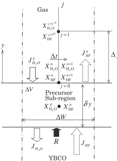
Let the numerical model of the YBCO growth in this study be restricted in two dimensions. A schematic illustration of one sub-region of the cross-section of the film, of which width is indicated asW, is shown in Fig. 1. It is assumed that the YBCO growth interface is parallel to the substrate surface in the sub-region. Consequently, theWvalue has to be short enough for the constant molar fraction of each gas component in the widthwise.
The computations have to be continued to obtain a quasi-steady state,e.g.constant distributions of the YBCO growth rates and the mole fractions of the components both in the gas and the precursor regions. Values of the volume,V, or the height,y, of the sub-region in the precursor in Fig. 1 do not change values in the steady state of XpH
2O and X
p
HF that are molar fractions of H2O and HF, respectively, since summa-tion of the molar flux of each component concerned with the sub-region could be zero in the steady state. Consequently, it is assumed that the volume of the sub-region in the precursor accompanied with the YBCO growth is constant.
Equations for conservation of the components, H2O and
HF, in the precursor in the sub-region of Fig. 1 are written as,
VMg @XpH
2O
@t ¼W ½JH2OJ
g
H2O;
VMg @XpHF
@t ¼W ½JHFJ g
HF; 8
> > < > > :
ð4Þ
respectively, whereMgis the molar density of the precursor, which is the same value as that of the gas,JHg
2OandJ
g
HFare values of molar fluxes for H2O and HF in the gas andJH2O
and JHF are those in the precursor. JHg2O and J
g
HF are represented by the Fick’s first law as,
JHg
2O¼ DH2OMg
@XH2O
@y ;
JHFg ¼ DHFMg @XHF
@y ;
8 > > < > > :
ð5Þ
respectively, whereXH2OandXHFare molar fractions of H2O
and HF in the gas region andDH2OandDHF are diffusivity
values of H2O and HF in the gas region, respectively. On the other hand,JH2OandJHF are expressed by using the reaction
equation, eq. (1) and the growth kinetics, eq. (2), as follows,
JH2O¼ 2MY123R¼ 2MY123ðkþX
p
H2Okþ=KX
p
HF 2
Þ;
JHF ¼4MY123R¼4MY123ðkþXpH2Okþ=KX
p
HF 2
Þ; (
ð6Þ
whereMY123is the molar density of the YBCO compounds. Assumption of the local equilibrium condition at the gas/precursor interface leads to,
XpH
2O¼XH2O; X
p
HF¼XHF: ð7Þ
Substituting eq. (7) into eq. (6) and eq. (5) into eq. (4) leads to,
2
1 H O
n j
X
=j
y
Gas
R
2
H O
J
J
HF2 g H O
J
g HF
J
1 HF
n j
X
=y
∆
2
H O
p
X
HFpX
2
H O
n
X
HF
n
X
2
1 H O
n
X
+1 HF
n
X
+t
∆
y
δ
W
∆
V
∆
YBCO Precursor Sub-region
1 j=
0 j=
[image:2.595.326.522.73.343.2]@XH2O
@t ¼
1
y 2MY123-gðkþXH2OkX
2
HFÞ þDH2O
@XH2O
@y
;
@XHF @t ¼
1
y 4MY123-gðkþXH2OkX
2
HFÞ þDHF @XHF
@y ; 8 > > > < > > > :
ð8Þ
where
1
y
W
V ; MY123-g MY123
Mg
: ð9Þ
The derivatives in eq. (8) are written in finite difference forms. Applying an implicit difference form to the time deviation,
@XH2O=@tand@XHF=@t, leads to,
@XH2O
@t ¼ XHnþ1
2OX
n
H2O
t ;
@XHF
@t ¼
XHFnþ1Xn
HF
t ; ð10Þ
whereXnandXnþ1are molar fractions of the respective component at the gas/precursor interface at the times ofntand ðnþ1Þ tas shown in Fig. 1. Applying the first order forward difference form to@XH2O=@yand@XHF=@yleads to,
@XHnþ1
2O
@y ¼ XHj¼1
2O
n
XnHþ1
2O
y ;
@XHFnþ1
@y ¼
XHFj¼1nXHFnþ1
y ; ð11Þ
where superscriptj¼1indicates the second grid point that is the grid sizeyaway from the gas/precursor interface as shown in Fig. 1. Substituting eqs. (10) and (11) into eq. (8) leads to,
XHnþ1
2OX
n
H2O
t ¼
1
y 2MY123-g kþX nþ1 H2OkX
nþ1 HF
2
þDH2Og X
j¼1 H2O
n
XnHþ1
2O
h i
Xnþ1
HF X
n
HF
t ¼
1
y 4MY123-g kþX nþ1 H2OkX
nþ1 HF
2
þDHFg XHFj¼1
n
XHFnþ1
h i 8 > > > < > > > :
ð12Þ
whereg1=y.
Expanding and reducing eq. (12), two quadratic equations aboutXnþ1 H2OandX
nþ1
HF are obtained as follows,
1þ2 t
yMY123-gkþþ
t
y DH2Og
XHnþ1
2O2
t
y kMY123-gX nþ1 HF
2
¼XnH
2Oþ
t
y DH2OgX
j¼1 H2O
n
;
4t
yMY123-gkþX nþ1
H2Oþ 1þ
t
y DHFg
XnHFþ1þ4t
y kMY123-gX nþ1 HF
2
¼XnHFþt
y DHFgX j¼1 HF n : 8 > > > > > > > > > > > > < > > > > > > > > > > > > :
ð13Þ
Solving the first equation in eq. (13) aboutXHnþ1
2Oleads to,
XnHþ2O1¼
2t
ykMY123-gX nþ1 HF
2 þXn
H2Oþ
t
yDH2OgX j¼1 H2O
n
1þ2t
y MY123-gkþþ
t
y DH2Og
: ð14Þ
Substituting eq. (14) into the second equation in eq. (13) becomes the quadratic equation aboutXnþ1
HF as follows,
4t
y kMY123-g 1
2t
yMY123-gkþ
1þ2t
yMY123-gkþþ
t
y DH2Og
0 B B B @ 1 C C C AX
nþ1 HF
2
þ 1þt
yDHFg
XHFn1
¼XHFn þt
y DHFgX j¼1 HF
n
þ
4t
yMY123-gkþ
1þ2t
yMY123-gkþþ
t
y DH2Og
XHn
2Oþ
t
yDH2OgX
j¼1 H2O
n
ð15Þ
XHFnþ1¼Bþ
ffiffiffiffiffiffiffiffiffiffiffiffiffiffiffiffiffiffiffiffi
B24AC p
2A ð16Þ
where,
A¼
4t
y kMY123-g
1þ2t
yMY123-gkþþ
t
y DH2Og
1þt
y DH2Og
ð>0Þ;
B¼1þt
y DHFg ð>0Þ;
C¼ XHFn þt
y DHFgX j¼1n
HF þ
4t
yMY123-gkþ
1þ2 t
yMY123-gkþþ
t
y DH2Og
XnH
2Oþ
t
y DH2OgX
j¼1 H2O
n
2 6 6 4
3 7 7 5
ð<0Þ: 8
> > > > > > > > > > > > > > > > > > < > > > > > > > > > > > > > > > > > > :
ð17Þ
The molar fractionsXnþ1 H2OandX
nþ1
HF at the next timeðnþ 1Þtat the gas/precursor interface are obtained by eqs. (14)– (17) when the molar fractionsXHj¼1
2O
n
andXHFj¼1nof the present timentat the grid pointj¼1in the gas region are obtained by solving the convective multi-component diffusion equa-tions. Thus, it is easy for the programs calculating the convective multi-component diffusion to include the proce-dures calculating eqs. (14)–(17) as one kind of boundary conditions for the gas region.
3.2 Convective multi-component diffusion in gas flow
In the TFA-MOD process, the water vapor partial pressure in the argon gas mixture atmosphere is supplied in the range
of 1–10 mol% and the twice values of moles of the HF gas of
the consumed H2O gas according to the YBCO growth
reaction as eq. (1) is released into the atmosphere. Thus, the molar fractions of H2O and HF are considered not to be dilute in the atmosphere and the multi-component diffusion treat-ment is necessary to analyze the transfer phenomenon of the gas components, H2O, HF and Ar. In addition, the convective effect for the gas component transfer caused by the supplied atmosphere gas flow has to be added to the multi-component diffusion equation.6,7) Consequently, the convective multi-component diffusion equations for the gas multi-components are written as follows,
@XH2O
@t þ
@
@xj
ðujXH2OÞ ¼
@
@xj
DH2O
@XH2O
@xj
XH2O DH2O
@XH2O
@xj
þDHF @XHF
@xj
þDAr @XAr
@xj
2 6 6 6 4
3 7 7 7
5; ð18Þ
@XHF
@t þ
@
@xj
ðujXHFÞ ¼ @
@xj DHF
@XHF @xj
XHF DH2O
@XH2O
@xj
þDHF @XHF
@xj
þDAr @XAr
@xj
2 6 6 6 4
3 7 7 7
5; ð19Þ
@XAr @t þ
@ @xj
ðujXArÞ ¼ @ @xj
DAr @XAr
@xj
XAr DH2O
@XH2O
@xj
þDHF @XHF
@xj
þDAr @XAr
@xj
2 6 6 6 4
3 7 7 7
5; ð20Þ
where uj is a gas flow velocity vector. It is noted that the
constant molar volume in the gas atmosphere is assumed in eqs. (18)–(20) because of incompressible gas flow as explained in next section.
The derivatives in eqs. (18)–(20) are transformed to the finite difference formulations. The up-wind difference of the third order accuracy and the central difference of the second order accuracy are applied to the advection terms in the second terms of the left hand sides and the diffusion terms in the right hand sides, respectively.8)
The spatially derivative values of the molar fractions of the
components, H2O and HF, in the neighborhood of the gas/
3.3 Gas flow
The actually supplied gas flow velocity is very small,i.e.a range of1103m/s and the gas pressure drop through the reaction furnace is also very small relative to the average pressure that is nearly equal to the atmospheric pressure. Thus, the supplied gas flow could be treated as the
incompressible flow, which is coincident with the assumption of the constant molar volume in the previous multi-component diffusion formulation.
The governing equations of the incompressible and viscous flow are written as follows,
@uj
@xj
¼0;
@uj
@t þui
@uj
@xi
¼ 1
@ij
@xi
; where ij¼2Vijþ p
2
3Vkk
ij;
Vij¼
1 2
@ui
@xj
þ@uj
@xi
;
¼XArArþXH2OH2OþXHFHF;
8 > > > > > > > > > > < > > > > > > > > > > :
ð21Þ
whereuiis the flow velocity vector,ijis the stress tensor,
is the viscosity,p is the pressure,Vijis the velocity gradient
tensor andis the mixture gas density. The first and second equations in eqs. (21) are the continuity and the momentum equations, respectively.
Transformation from eqs. (21) to the finite difference equations are performed by the same manner as the previous formulation for the convective multi-component diffusion equations. Subsequently, the grid mesh used for the discrete formulations for eqs. (18)–(19) is also applied to numerically solve the finite difference equations of eq. (21). Finally, these finite difference equations are numerically solved by using
highly simplified maker and cell (HSMAC) method.9)
4. Calculations
The configuration in the reaction furnace for the TFA-MOD process, in which the YBCO growth rates were measured, is shown in Fig. 2. The precursor coated films were placed on the surface on the holder in the furnace, heated up to 775C at a rate of 25C/min and held for 60–180
minutes. The details of the experimental conditions can be referred to the article reported by R. Teranishiet al.2)
Calculations were performed in the two dimensional region as shown in Fig. 2, of which boundaries of inflow and outflow are enough far from the film for the normal gradient of the molar fraction to be nearly constant, which
preserves the Neumann boundary condition. The upper and bottom boundaries in Fig. 2 were located on the reaction furnace wall and the film holder surface, respectively. The YBCO growth rates were calculated in different cases of the film lengths,L¼10, 20 and 30 mm.
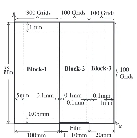
The conditions of the grid generation, numbers of the grid and the grid size for the calculation region in the case of
L¼10mm are shown in Fig. 3. The grid generation was
performed for the grid distribution to be dense in the neighborhood of the film surface. All grids consist of the three blocks, which are horizontally connected in series. The rectangle and non-uniform grids were generated in each block. The grid sizes on both sides for horizontal and vertical directions in each block are indicated in Fig. 3. The horizontal grid size in Block-2 that placed on the film was constant to be 0.1 mm, in all cases ofL¼10, 20 and 30 mm. Thus, the horizontal number of grids in Block-2 was 200 and 300 in the cases ofL¼20and 30 mm, respectively. The grid sizes monotonously vary from the grid size on the side to one on the other side for the horizontal direction in other blocks
100 Grids 25
mm
L=10mm
x y
100mm 20mm
0.05mm 5mm
1mm
0.1mm 0.1mm
0.1mm
0.1mm 1mm
300 Grids 100 Grids 100 Grids
Film
Block-1 Block-2 Block-3
Fig. 3 The sizes of calculated region, number of grid and grid sizes.
100mm
800mm
Dia.
50mm
Ar + H
2O
Ar + H
2O
+ HF
Film
10,20,30mm
Calculated
Region
Film Holder
[image:5.595.313.540.272.501.2] [image:5.595.58.280.620.757.2]and for the vertical direction in all blocks.
The boundary conditions of the molar fraction and the gas flow velocity and the pressure are shown in Fig. 4. The boundary conditions of the molar fractions at the precursor coated film were given by eqs. (14) and (16). In order to investigate the inlet water vapor molar fraction dependence of the YBCO growth rate, the calculations were performed in the cases of XIN
H2O¼0:8, 2.1, 8.4 and 18.9% for the film
length L¼10mm and inlet gas velocity u1¼8:49103
m/s. In order to investigate the inlet gas flow velocity dependence, simulation calculations were performed in the
cases of u1¼2:12103, 4:24103 and 8:49103
m/s for the film lengthL¼10mm.
Computation solving both the convective multi-compo-nent diffusion equations of eqs. (18) and (19) and the Navier-Stokes equation of eq. (21) requires lots of computer processing time. Therefore, for reducing the amount of the computation time, a simplification for the Navier-Stokes equation, eq. (21) was applied. In the right hand side of eq. (21), the density of the gas is provided as ¼XArArþ
XH2OH2OþXHFHF. On the other hand, the viscosity
might be variable according to the molar fractions of the components. However, it is difficult to obtain the precise value of the mixed gas viscosity. It is then assumed that the value of the density and the viscosity in the right hand side of eq. (21) are equal values in the Ar gas atmosphere, which were 0.487 kg/m3and5:50105kgm1s1, respectively, at 775C.10)Consequently, eq. (21) was numerically solved only once in advance of performing computations of eqs. (18) and (19).
In this two-dimensional calculation, distributions of the gas flow, the gas component fractions and the growth rates for the normal direction in Fig. 2 are not estimated. Thus, the
symbol K in eq. (2), which is the exact value of K in the
three-dimensional space, is not directly applicable to eq. (6) in the present calculations. Therefore, a parameterinstead
ofKwas used in eqs. (2) and (6). Thevalue is equal to theK
value in the experimental condition that realizes the two-dimensional distributions of the diffusion and the gas flow. However, the diffusion phenomena around the one cm wide film in the reaction furnace illustrated in Fig. 2 behave three-dimensionally. Consequently, the value is rather different from theKvalue.
5. Results and Discussions
5.1 Consistency of analytical and numerical models
It was revealed for the present numerical YBCO growth model to be consistent with the analytical solution, eq. (3), by one-dimensional numerical analysis as follows. It was reported that the YBCO growth rates using the values of
the constants, M123=Mg¼11:4104, Dg¼2104
m2/s,
g¼1:25cm and K¼11:1108, in eq. (3) were
in good agreement with the experimentally measured ones at the 1 cm film center in the conditions ofu1¼8:49103
m/s and for different XIN
H2O values.
4) One-dimensional
formulations for eqs. (18)–(20), in which the convective terms were neglected, with the YBCO growth model eqs. (14)–(17) were numerically solved using these constant values. In this calculation, the diffusivities, DAr, DHF and
DH2O, were assumed to be the same value as Dg¼2
104m2/s and the gas region height was made to be equal as
g¼1:25cm. Figure 5 shows that the calculated growth
rates behave according to a square root ofXHIN
2Odependence
and agree with the growth rate values provided by eq. (3) very well.
It is noted that the previousKvalue may be different from the precise one in the field consisting of the three dimensional gas flow and diffusion, since it is difficult to obtain the precise
Kvalue explicitly. However, if the preciseKvalue is known, eq. (3) will be held rightfully by making a appropriate choice
of the g value that includes the effects of the gas flow
velocity and multi-dimensional distributions of the gas component fractions.
x y
2 IN
H O Const.
X =
HF
0 ∂X
n =
∂
1
2
Const. 0 u u
= =
0
p=
0 p n ∂ = ∂
0 p n ∂ = ∂ 0
i u
n
∂ =
∂
2
H O
0 X
n
∂ = ∂
HF 0
X n
∂ = ∂
Calculating Equation (16)
1 HF
n
X
+Substituting into Equation (14)
2
1 H O
n
X +
2
H O
0 X
n
∂ = ∂
HF 0
X n
∂ =
∂ 0
i u
n
∂ =
∂ 0
p n ∂ = ∂
0
i u
n
∂ = ∂
HF 0
X n
∂ = ∂
2
H O
0 X
n
∂ = ∂
Fig. 4 The boundary conditions of molar fraction and gas flow velocity and pressure.
0 2 4 6 8
0 1 2 3 4 5
Experimental Analytical Numerical
2 IN H O / %
X
4) 4)
Square Root of H2O Molar Fraction,
Growth Rate,
R
/ 10
-10
ms
-1
[image:6.595.62.276.72.304.2] [image:6.595.327.525.549.746.2]5.2 XIN
H2O dependence of growth rate Figure 6 shows theXINH
2Odependence of the growth rate at
the center in the one cm wide film, which was calculated in the condition for the inlet gas velocity of,u1¼8:49103 m/s. It is verified that the inlet water vapor molar fraction dependence of the YBCO growth rate obtained by the two dimensional calculations agrees very well with the exper-imental results.
In these calculations, the used value ofwas29:0108
that was nearly three times as large as the K value (K¼
11:1108) for the previous one-dimensional model. The
distribution of the HF molar fraction is shown in Fig. 7. It could be identified for the boundary layer to broaden more than the assumed one dimensional boundary thickness of
g¼1:25cm. Thus, the largervalue than theKvalue of the one dimensional analysis is necessary to estimate the growth rate to obtain the same value as experimental one. The
present value, 29:0108, was used in all present two
dimensional calculations.
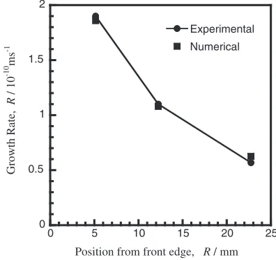
5.3 Positional dependence of growth rate
Figure 8 shows the positional dependence of the growth rate in the conditions for the inlet gas velocity ofu1¼8:49
103m/s andXIN
H2O¼2:1%, in which the growth rate values
are plotted at 5.15, 12.25 and 22.75 mm from the front edges of the films in the cases of the film lengths ofL¼10, 20 and 30 mm, respectively. It can be seen as well that the calculated results agree well with the experimentally measured ones.
These results suggest that the effects of the convective multi-component diffusion in the three-dimensional space on the distribution of the YBCO growth rate were well simulated by the present two dimensional calculations using the
constantvalue.
Molar Fraction of HF
Film
Fig. 7 Steady state distribution of the HF molar fraction obtained in the conditions of film length: 10 mm, inlet molar fraction of H2O: 2.1% and inlet gas flow velocity:8:49103m/s.
0 2 4 6 8
0 1 2 3 4 5 Experimental
Analytical
Numerical
4)
4)
2
IN
H O / %
X
Square Root of H2O Molar Fraction,
Growth Rate,
R
/ 10
-10
ms
-1
Fig. 6 Square root of H2O molar fraction dependence of the growth rate. Solid square shows the growth rate obtained from two-dimensional calculations.
Position from front edge, R / mm 0
0.5 1 1.5 2
0 5 10 15 20 25
Experimental
Numerical
Growth Rate,
R
/ 10
-10
ms
-1
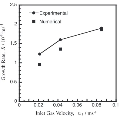
[image:7.595.71.270.71.270.2] [image:7.595.326.524.75.262.2] [image:7.595.109.489.339.527.2]5.4 Gas flow velocity dependence
Figure 9 shows the inlet gas flow velocity dependence in the conditions of XIN
H2O¼2:1% and the film length of L¼
10mm, in which the calculations were performed in the cases ofu1¼2:12103,4:24103and8:49103m/s. The tendencies are similar in numerical results and the exper-imental measurements.
However, it is seen that the deviation of the growth rate values between calculation and experiment grows as the inlet gas flow velocity decreases. The reason for this tendency is considered as follows; the transport phenomena of the gas components tend to be controlled by the two-dimensional boundary layer caused by the one-directional inlet flow parallel to the film surface as the inlet gas flow velocity increases. On the other hand, as the inlet gas flow velocity decreases, the gas components rather tend to diffuse three-dimensionally over the film in the reaction furnace.
The present YBCO growth model and numerical proce-dures can be, however, directly applicable to the three-dimensional system. Thus, it is supposed that the above deviation for the gas flow velocity dependence is to be
removed and thevalue is to approach the preciseKvalue
by performing the three-dimensional calculations.
6. Conclusion
In this article, the numerical analyses for the YBCO
growth in the TFA-MOD process considering the gas flow, the gas component diffusion and the growth kinetics at the precursor/YBCO interface are conducted by constructing and performing the two-dimensional calculating procedures. As a result, it could be seen that the calculated results agree very well with the experimental results on investigations for the supplied water vapor molar fraction dependence, posi-tional dependence and gas flow velocity dependence of the growth rate. Consequently, it is confirmed that the present growth model and the numerical procedure will become a powerful tool to design the suitable configurations and conditions in the reaction furnace to efficiently produce the YBCO conductor films.
Acknowledgments
This work was supported by the New Energy and Industrial Technology Development Organization (NEDO) as Collaborative Research and Development of Fundamental Technologies for Superconductivity Applications.
REFERENCES
1) T. Honjo, H. Fuji, Y. Nakamura, T. Izumi, Y. Shiohara, R. Teranishi, M. Yoshimura, J. Shibata, T. Yamamoto and Y. Ikuhara: CP614, Advances in Cryogenic Engineering: International Cryogenic Materials Conference-ICMC, Vol. 48, (2002 American Institute of Physics) pp. 581–587.
2) R. Teranishi, H. Fiji, T. Honjo, Y. Nakamura, T. Izumi, Y. Shiohara, J. Shibata, T. Yamamoto, Y. Ikuhara and M. Yoshimura: Physica C
378–381(2002) 1033–1038.
3) T. Honjo, H. Fuji, Y. Nakamura, T. Izumi, Y. Shiohara, J. Shibata, T. Yamamoto, Y. Ikuhara, R. Teranishi and M. Yoshimura: J. Japan Inst. Metals66(2002) 151–154.
4) T. Honjo, Y. Nakamura, R. Teranishi, Y. Tokunaga, H. Fuji, J. Shibata, S. Asada, T. Izumi, Y. Shiohara, Y. Iijima, T. Saitoh, A. Kaneko and K. Murata: Physica C392–396(2003) 873–881.
5) T. Honjo, Y. Nakamura, R. Teranishi, H. Fuji, J. Shibata, T. Izumi and Y. Shiohara: IEEE Trans. Appl. Superconductivity13(2003) 2516– 2519.
6) M. E. Glicksman:Diffusion in Solid, (John Wiley & Sons,Inc., 2000) pp. 391–404.
7) R. B. Bird, W. E. Stewart and E. N. Lightfoot:Transport Phenomena, Second Edition (John Wiley & Sons,Inc., 2002) pp. 582–611. 8) T. Kawamura and K. Kuwahara: AIAA paper 84-0340 (1984) 9–12. 9) A. A. Amsden and F. H. Harlow: J. Comput. Phys.6(1970) 322–325. 10) Edited by K. Katayama: JSME Data Book, Heat Transfer, 4th Edition
(JSME, 1986) p. 328.
Inlet Gas Velocity, u1/ ms-1
0 0.5 1 1.5 2 2.5
0 0.02 0.04 0.06 0.08 0.1
Experimental
Numerical
Growth Rate,
R
/ 10
-10
ms
-1
[image:8.595.71.269.71.265.2]