Solidification Behaviour and the Evolution of Microstructure in the Laser
Cladding of Aluminium on Magnesium Substrate
T. M. Yue and T. Li
The Advanced Manufacturing Technology Research Centre, Department of Industrial and Systems Engineering, The Hong Kong Polytechnic University, Hung Hom, Hong Kong, P. R. China
Laser cladding of aluminium powders was performed on pure magnesium substrates using the blown powder method. The microstructure across the laser-clad track was studied. Starting from the bottom of the laser-clad to the top surface of the track, a series of microstructures was observed: a planar growth interface of the substrate, a narrow band of (þ) eutectic, a narrow band ofcellular structure, and finally a relatively thick layer of-Al and (þ) eutectic structure. The evolution of the various phases and microstructures is discussed in terms of the distribution of solute in conjunction with the Al-Mg phase diagram, temperature gradient and solidification rate, constitutional supercooling theory, and the condition for columnar-to-equiaxed crystal transition. [doi:10.2320/matertrans.48.1064]
(Received December 11, 2006; Accepted February 27, 2007; Published April 25, 2007)
Keywords: laser cladding, solidification, interface stability, equiaxed crystal, cellular structure
1. Introduction
The ever increasing demand for light-weight materials for engineering applications, especially for the aerospace and automobile industries makes the development of magnesium-based materials with improved properties a pressing issue. Notwithstanding the advances that have been made in alloy development, magnesium alloys still suffer from the inher-ently undesirable properties of poor corrosion and wear resistance, which seriously impede the wider application of the alloys. Over the years, intensive research efforts have been devoted to overcoming these shortcomings. High-power laser cladding, a surface engineering technique, has shown great potential for improving the surface properties of magnesium alloys.1–4)An essential factor for the success of
laser cladding is the achievement of a strong metallurgical bond over the entire interface between the substrate and the clad-layer. It is understood that the formation of a strong bond between the clad and the substrate is chiefly governed by the solidification condition and behaviour at the interface between the two. Moreover, the properties of the clad-layer relate largely to its grain structure. Therefore a good understanding of the solidification behaviour of the laser-melt zone is vital.
The results of previous research studies on the laser cladding of various metals on Mg-based substrate have indeed provided valuable information on the solidification behaviour of the clad-layer. The early work of Subramanian and Wang on laser cladding of Mg-Zr and Mg-Al alloys on magnesium substrates1,2)resulted in some useful information
in relating laser-cladding parameters to microstructure and corrosion properties. It was reported that2) the improved
corrosion resistance of the Mg-Al cladded magnesium substrate was due to the presence of a randomly oriented polycrystalline structure. However, the work did not analyse the evolution of the polycrystalline structure. Similar work was performed by Majumdar,5,6) where systematic studies were conducted on the laser surface treatment of Mg-based alloys, with different alloying elements, for improving the corrosion resistance of the magnesium substrate. More
recently, Ignat7)studied the laser cladding of aluminium on
magnesium alloys WE43 and ZE41. The resulting micro-structure was analysed and some mechanical properties were determined. Nonetheless, most of these previous works focussed mainly on revealing the influences of laser processing parameters upon microstructure with much effort spent on the characterisation and identification of the phases present in the laser-clad coating. Notwithstanding the con-tributions of these studies, it is considered that our under-standing on the solidification behaviour and phase evolution in laser cladding of protective layers on Mg-based materials is still far from satisfactory, especially in modelling the evolution of microstructure. With this background in mind, the present research aims to study the solidification behaviour and phase evolution in the laser cladding of aluminium on magnesium substrate using the constitutional supercooling theory and the columnar-to-equiaxed transition model.
2. Experimental Method
Commercially pure aluminium powder was laser cladded onto a commercially pure cast magnesium substrate (30 3010mm, purity>99:9mass%) using a one-step blown powder method. The surface of the substrate was cleaned by sandblasting prior to laser cladding. In order to eliminate any water that may be trapped in the powder, the specimens were dried in a vacuum oven for 24 hours. The cladding experi-ment was conducted in a laser rapid forming system that consisted of a 5 kW continuous wave CO2 laser from Rofin
Sinar, a four-axis numerical control working table, and a powder feeder with a lateral nozzle. The experiment was conducted inside a chamber, the atmosphere of which was controlled. The laser was mounted on an overhead carriage and the beam was directed into the chamber through a window on top of it. The controlled-atmosphere chamber was filled with argon gas, and argon gas was also used to deliver the metal powder to prevent the molten pool from oxidizing and oxide contamination from occurring during processing. The laser beam was directed onto the substrate to create a shallow molten pool and at the same time aluminium powder
was delivered into the pool using a lateral powder feeder. The metal powder was melted and subsequently re-solidified to form the laser-clad track. The powder was delivered to the molten pool by an argon jet with a metal flow rate of 83 cm3/s. When using such a system, the thickness and the
profile of the track can be easily controlled. The laser beam was focused to a spot of 1.4 mm. The laser scanning rate was 5 mm/s and the laser power employed was 2 kW. Using these conditions, single tracks with a thickness of about 0.8 mm were produced.
The specimens for microscopic study were ground with a series of emery papers and then polished with 1mmdiamond abrasives. The microstructure of the material was revealed using an etchant of 5cc acetic acid, 6g picric acid, 10cc water, and 100cc ethanol (95%). The microstructure and phases of the laser-clad tracks were characterized using a Leica microscope, a Philips XRD System, and a Leica scanning electron microscope equipped with energy dispersive X-ray spectroscopy (EDS).
3. Results and Discussion
3.1 Microstructure
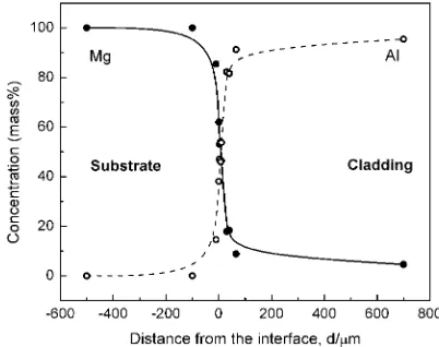
Figure 1 shows the backscattered electron image of a transverse section of a laser-clad track. A dense cladding with a defect-free metallurgical bonded interface with the sub-strate was obtained. A clear boundary existed between the substrate and the clad layer. The results of an EDS analysis across the clad-layer and the substrate (Fig. 2) show that a dilution zone of thickness of about 150mm formed at the interface region. In this case, the dilution zone is defined as the region where the amount of inter-diffusion of elements exceeded 10 mass%. Beyond this zone, the compositional gradient was sharply reduced, which indicates that the mixing of the cladding material, i.e. aluminium with the substrate material was not serious. The presence of about 5 mass%Mg in the entire clad-layer is considered to be due to the high diffusion rate of magnesium in aluminium. This result is similar to that obtained for the study of the laser cladding of an Al-Si eutectic alloy on a magnesium composite,3)where the main dilution effect was confined to the interface region. This is also in agreement with many previous studies that show strong convection currents in the laser-melt pool might
not be sufficient for achieving a complete chemical and structural homogenised structure.8–10)
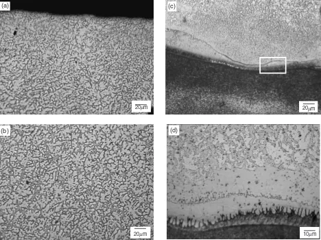
Figure 3 shows the microstructure of a transverse cross-section of a laser-clad track. Towards the surface, the microstructure consists mainly of fine equiaxed -Al den-drites (Fig. 3(a)), and only a relatively small amount of eutectic phase present at interdendritic regions. While moving towards the substrate, the amount of eutectic phase increases (Fig. 3(b)). Near the bottom of the laser-cladding, the microstructure was dominated by a eutectic phase (Fig. 3(c)). A closer examination of the interface between the substrate and the clad-layer shows a continuous growth of a cellular band structure (Fig. 3(d)), and the growth direction was found to be towards the substrate. This is quite different from the epitaxial growth normally found in laser cladding. To confirm whether the cellular growth is continuous along the track of the laser-clad, a longitudinal section of the specimen was prepared. Figure 4 clearly illustrates that a continuous band of cellular structure existed along the interface of the laser-clad. The figure also shows a band of fine eutectic phase is present between the substrate and the cellular layer. A high magnification image of the region ahead of the solidification front of the substrate clearly shows the presence of the cellular structure and a band of fine eutectic structures (Fig. 5). In fact, such a backward growth of cellular structure can be found in the results of the study of Ignat7)and Miyamoto11)on laser cladding of Al on Mg and Cu on Al respectively, but unfortunately the phenomenon was not discussed. An XRD analysis was conducted to determine the various phases present at the interface region between the substrate and the cellular layer. The results show that intermetallic phases,(Mg2Al3),0(Mg0:42Al0:58) and
(Mg17Al12), are present (Fig. 6). Based on the results of the
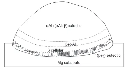
XRD analysis and the metallurgical examination, a schematic diagram is presented in Fig. 7 summing up the major phases present across the laser-clad track. Referring to this figure, the narrow band of (þ) eutectic and the-cellular layer formed ahead of the substrate interface is considered to be undesirable. This is because these two intermetallics are brittle phases,12,13)and would not be able to accommodate high stresses in service. The following sections will discuss the evolution of the various microstructures across the laser-clad track.
200µm Cladding
Substrate
Fig. 1 A SEM backscattered electron image of a transverse section of
[image:2.595.324.525.72.231.2] [image:2.595.57.285.73.226.2]3.2 Magnesium substrate interface
In the present study, a planar solidification front was observed at the boundary of the magnesium substrate. It is clear that laser cladding conditions would influence the temperature gradient Gand the solidification rate V of the molten pool. On the other hand, the composition of the molten pool would determine the magnitude of the freezing
range, which in turn would affect the type of microstructure formed in the clad-layer. Also, in laser surface melting, the growth velocity (V) of the solid/liquid interface that has the cellular, planar or eutectic morphology can be related to the scanning velocity of the laser beam (VS):
V ¼VscosðÞ ð1Þ
where is the angle between the vector representing the
20 mµ (a)
20µm (b)
20µm (c)
(d)
10µm
Fig. 3 Microstructure of a laser-cladding: (a) near the top of the track, (b) in the middle, (c) towards the bottom, (d) an enlargement ahead of the substrate interface.
10µm Substrate
Laser scanning direction
Fig. 4 A longitudinal section showing a continuous band of cellular structure.
ββ cellular
Substrate
(β + γ) eutectic
2µm
[image:3.595.65.533.78.428.2] [image:3.595.55.284.481.653.2] [image:3.595.313.542.481.636.2]direction of the transverse movement of the substrate and the vector normal to the solid/liquid interface. It is understand that the solidification rate V varies throughout the solid-ification process from a minimum at the fusion boundary of the substrate (whereapproaches 90) to a maximum at the
surface of the clad-layer (where approaches 0). In the
present study, the angle was measured in terms of the orientation of the growth direction of the cellular structure from a longitudinal-section of a laser-clad specimen. From the measurement, an average value of 85.4was obtained for
50 cellular stems. The value ofVS used in this study was 5 mm/s. Given these conditions, V was calculated for the magnesium substrate to be 0.4 mm/s. This solidification rate was found to be relatively small. This agrees with most of the previous studies14–16)in thatVwas found to be virtually zero at the bottom of the laser-melt pool, and increased to a maximum towards the surface of the melt. Now, because the solidification rate was found to be relatively low at the bottom of the molten zone, the morphology of solidification growth can be determined by the constitutional supercooling theory.17) If the solidification condition prevails that the
condition of eq. (2) is met, then the morphology of the solid-liquid interface would remain planar; otherwise it would become unstable and the interface may develop into a cellular or dendritic structure. The condition that needs to be satisfied is,
G
V >
m0C0ðk01Þ
k0DL
ð2Þ
where m0 is the slope of the liquidus line,C0 is the alloy
constitution,k0 is the distribution coefficient, andDLis the diffusion coefficient.
According to eq. (2), the lowest critical temperature gradient (Gc) in the liquid to ensure the stable growth of a planar interface was calculated. In the calculation, an alloy with a composition of Mg-10 mass%Al was assumed, this was based on the average composition profile (Fig. 5) measured ahead of the magnesium interface.
GC ¼
m0C0ðk01ÞV
k0DL
¼3:7510 ð0:11Þ
0:31:8109 ¼250K/cm ð3Þ
Since this calculated value for planar growth is much lower than the value of G that normal exists in laser cladding (>1103K/cm), a planar solidification front is therefore
expected for the present study. And this agrees with the experimental result obtained, namely that a planar growth front was observed at the boundary of the magnesium substrate.
3.3 The cellular growth
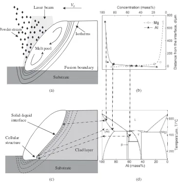
Ahead of the planar growth front of the magnesium substrate, there was a narrow eutectic band zone together with a layer of cellular structure whose direction of growth is towards the magnesium substrate. To explain the develop-ment of microstructure ahead of the magnesium substrate interface, the information about the composition profile (Fig. 2) together with the binary Al-Mg phase diagram, were utilised. Based on this information, isotherms which match the corresponding phase field of the phase diagram (Fig. 8) were created. According to the results, there is a low melting point (þ) eutectic phase lying ahead of the magnesium planar interface. This is believed to be due to the fact that the fast growing solidification front was moving from the top side of the molten pool, while the planar solidification front of the magnesium substrate was moving extremely slowly. As a result, the low melting point eutectic phase was trapped just ahead of the magnesium planar interface.
Regarding the cellular structure, as solidification proceeds towards the bottom of the molten pool, the growth of primary
phase occurs, and solute of Mg is rejected ahead of the solidification front. As a result, constitutional supercooling can occur, and the initial planar interface ofphase would become unstable when exposed to a gradient of supercooling, and perturbations would develop. Finally, this leads to the development of a cellular structure of phase with the growing direction towards the solidifying liquid. As was mentioned previously, the presence of the brittle phase is undesirable, and in order to suppress its formation, it is necessary to establish a solidification condition that favours the epitaxial growth of Al on Mg.
3.4 The morphology of-Al dendrite
It is apparent that in the laser-clad track, no sign of columnar growth of primary-Al is found. The-Al dendrites solidified in the form of equiaxed crystals with the interdendritic regions filled with the eutectic phase of (-Al+). The reason for this can be explained on the basis of the condition for columnar-to-equiaxed transition (CET), which was developed by Hunt.18) Fig. 6 The results of an x-ray diffraction analysis of the region ahead of the
substrate interface that makes up the cellular and the fine eutectic structures.
αAl+(αAl+β)eutectic
(β+γ) eutectic
β cellular
β+αAl
Mg substrate
[image:4.595.71.271.69.207.2] [image:4.595.62.274.269.384.2]He first developed an analytical model to describe the steady-state conditions for the growth of columnar and equiaxed crystals, which reveals the effects of alloy composition, nucleation density and cooling rate on CET. According to the model, the critical thermal gradient for a fully equiaxed growth can be expressed as:
G<0:617N01=3 1 ðTNÞ3
ðTCÞ3
TC ð4Þ
where N0 is the total number of heterogeneous substrate
particles originally available per unit volume, TN is the
undercooling at the heterogeneous nucleation temperature. TC is the undercooling at the columnar front, which can be
expressed as:
TC¼ VC0
A 1=2
ð5Þ
where A is a constant.
Based on this model, the CET curve for Al-10 mass% Mg and Al-5 mass% Mg alloys were determined. These two compositions were selected because the composition gradient measured across the laser-clad track shows that the content of magnesium in the primarily -Al dendrites zone, roughly ranged between 10 mass% and 5 mass%. In the present work, the value ofN0was assumed to be 1000 per cubic millimetre.
This was according to the analysis of Lin,19)T
Nwas taken
to be 0.75 K.18)Other thermophysical parameters used for the
calculations of are given in Table 1. The value of constantA was calculated by combining the KGT model20)and Hunt’s
analysis.18) The relationship between T-V was obtained
from the KGT model, then according to the equation,
T ¼GD
V þ
C0V
A 1=2
ð6Þ
the value of A was acquired using nonlinear regression analysis of theT-V relationship.
(c) (d)
Cellular structure
VS
Solid-liquid interface
Clad layer
Substrate Laser beam
Substrate Melt pool
Fusion boundary
(a) (b)
Isotherms Powder stream
[image:5.595.115.484.68.443.2]Fig. 8 The relationships between the composition profile, the Al-Mg phase diagram, and the corresponding microstructure in the laser-clad track.
Table 1 Thermophysical parameters for the Al-Mg system.
Slope of liquidus (k/wt. pct.)
Diffusion coefficient (cm2/s)
Distribution coefficient
Gibbs-Thomson coefficient (k cm)
4:8 9.90E-5expð8610=TÞ21Þ 0.4 1.3E-522Þ
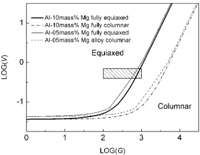
[image:5.595.43.551.502.539.2]The CET curves for the two alloys were obtained and are presented in Fig. 9. The figure also gives the experimental conditions of the present study. It should be pointed out that, during laser cladding, the temperature gradient decreases continuously, and the solidification velocity increases grad-ually from the bottom of the molten pool to the top. So the solidification conditions are changing as solidification pro-ceeds and the shaded region in Fig. 9 represents the changes. The predictions show that within the limits of the compo-sition studied and the experimental conditions experienced in the study, the preferred crystal structure for the majority potion of the laser-clad track should be in the form of equiaxed. This is in good agreement with the observed microstructure of the main portion of the laser-clad track.
4. Conclusions
Dense aluminium single tracks with a good metallurgical bond were formed on magnesium substrates using the blown powder laser cladding method. A relatively narrow compo-sition diffusion zone was detected at the substrate-clad interface; in the main portion of the clad, an average content of 5 mass%Mg was measured. As to the microstructure, the laser-cladding consists primarily of fine dendrites of-Al and
-Al+ eutectic. This was found to be due to the high
thermal gradient that existed in the process of laser cladding and the strong tendency of columnar-to-equiaxed transition for Al-Mg alloys. Ahead of the solidification boundary of the substrate, a band of cellular structure was found; the phenomenon was explained in terms of constitutional super-cooling. The presence of a continuous band of cellular structure is considered to be undesirable, because it is a brittle
phase. With regard to the solidification behaviour of the substrate material, a planar growth interface was obtained. This was found to be due mainly to the low growth rate that was experienced in the magnesium substrate.
Acknowledgements
The work described in this paper was fully supported by a grant from the Research Grants Council of the Hong Kong Special Administrative Region, China (Project No. PolyU 5312/05E). The authors also thank the Hong Kong Poly-technic University and Northwestern PolyPoly-technical Univer-sity for providing the research facilities.
REFERENCES
1) R. Subramanian, S. Sircar and J. Mazumder: J. Mater. Sci.26(1991) 951–956.
2) A. A. Wang, S. Sircar and J. Mazumder: J. Mater. Sci.28(1993) 5113– 5122.
3) T. M. Yue, A. H. Wang and H. C. Man: Scripta Mater.40(1999) 303– 311.
4) J. E. Gray and B. Luan: J. Alloy. Compd.336(2002) 88–113. 5) J. Dutta Majumdar, R. Galun, B. L. Mordike and I. Manna: Mater. Sci.
and Eng. A361(2003) 119–129.
6) J. Dutta Majumdar, B. Ramesh Chandra, B. L. Mordike, R. Galun and I. Manna: Surface and Coatings Technology179(2004) 297–305. 7) S. Ignat, P. Sallamand, D. Grevey and M. Lambertin: Appl. Surf. Sci.
225(2004) 124–134.
8) X. He, B. L. Mordike, N. Pirch and E. W. Kreutz: Lasers in Eng.4 (1995) 291–316.
9) P. Mohan Raj, S. Sarkar, S. Chakraborty, G. Phanikumar, P. Dutta and K. Chattopadhyay: International Journal of Heat and Fluid Flow23 (2002) 298–307.
10) N. Chakraborty, D. Chatterjee and S. Chakraborty: Numerical Heat Transfer A46(2004) 1009–1032.
11) I. Miyamoto, S, Fujimori and K. Itakura: ICALEO ‘‘97’’, ed. by R. Fabbro, A, Karr and A. Matsunawa, (Laser Institute of America, 1997) pp. F1–F10.
12) D. P. Shashkov: Metallurg39(1995) 21–25.
13) S. Kleiner, O. Beffort, A. Wahlen and P. J. Uggowitzer: Journal of Light Metals2(2002) 277–280.
14) W. Kurz and R. Trivedi: Trans. ASME114(1992) 450–458. 15) Z. X. Liu: Ph.D. dissertation, Northwestern Polytechnical University,
China, 2003.
16) Y. P. Su: Ph.D. dissertation, Northwestern Polytechnical University, China, 2004.
17) W. A. Tiller, K. A. Jackson, J. W. Rutter and B. Chalmers: Acta Metall. 1(1953) 428–437.
18) J. D. Hunt: Materials Science and Engineering65(1984) 75–83. 19) X. Lin, Y. M. Li, M. Wang, L. P. Feng, J. Chen and W. D. Huang:
Science in China (Series E)46(2003) 475–489.
20) W. Kurz, B. Giovanola and R. Trivedi: Acta Metall. Mater.34(1986) 823–830.
21) M. Gu¨ndu¨z and J. D. Hunt: Acta Metall.37(1989) 1839–1845. 22) A. S. Yue: Journal of Crystal Growth42(1977) 542–546. Fig. 9 The predicted regions for columnar crystal growth and equiaxed
[image:6.595.68.269.70.226.2]