Evaluation of Rolling Fatigue Damage in Deep Groove Ball Bearings
by Divided-Type Focusing Ultrasonic Transducer
Yorinobu Murata
1, Hiroki Toda
1, Chiaki Tawa
1, Masahiro Kiji
2and Noriyasu Oguma
2 1Faculty of Systems Engineering, Wakayama University, Wakayama 640-8510, Japan 2Research & Development Center, JTEKT Corporation, Kashiwara 582-8588, Japan
To evaluate quantitatively the damage caused by rolling fatigue in deep groove ball bearings, we used a method in which the wave velocity of a leaky surface acoustic wave (SAW) propagating on the race surface of bearings was measured. The wave velocity was directly measured from the change in the propagation time by defocusing a focusing ultrasonic transducer. A new focusing ultrasonic transducer was developed by molding a piezoelectric copolymer into a concave-shaped film. To fabricate ultrasonic transducers with a lower frequency characteristic, the films were stacked and composite backings made from epoxy resin and tungsten were used. The electrode of the transducer was divided into three areas to receive direct reflection waves and leaky SAW independently without any interference. Two of these electrodes were used for the excitation and reception of leaky SAW, and the shape of the electrodes was designed so that leaky SAW might propagate only on the raceway surface of the inner ring of the bearings. Moreover, in order to suppress the effects caused by edge waves, the shape of the electrodes for leaky SAW was considered. The availability of this method was evaluated by measuring the leaky SAW velocity in the bearings whose worked hours differed. As a result, a small difference in leaky SAW velocity was detected according to the worked hours of the bearings, and it was demonstrated that this method would be useful for non-destructive soundness evaluation of bearings.
[doi:10.2320/matertrans.I-MRA2007855]
(Received September 4, 2006; Accepted April 9, 2007; Published May 25, 2007)
Keywords: ultrasonic wave velocity, rolling fatigue, deep groove ball bearing, leaky SAW, piezoelectric copolymer, P(VDF-TrFE), edge wave
1. Introduction
The reliability of machine parts is a factor that has gained considerable attention in recent times. Therefore, a clear understanding of the changes in the fatigue conditions of machine parts is essential in order to secure the soundness of various mechanical systems. A bearing is a main machine component that imparts flexibility to mechanical systems, and it is indispensable in most rotation parts (wheels, motors, etc.). Therefore, even if only one of the bearings in a machine is damaged, it could lead to the fatal damage of the entire system. Problems caused by the material defects in bearings have been decreasing due to improvements in the cleanliness factor of materials and the heat treating technologies developed in steel manufacture. Due to increasing demands with regard to miniaturization, high rotational speed, and long life, the environment in which bearings will be placed is becoming more severe. When bearings are used over a long period of time, fatigue is accumulated in the race region. Fatigue causes damage such as flaking in the race region. The life of rolling bearings is generally estimated by the life-evaluating equation provided in ISO 281.1)The calculated
value obtained from this equation is effective for a group of bearings, and this value becomes an important standard in the design stage. However, when this equation is applied to the evaluation of individual bearings that work in a particular region of a mechanical system, an incorrect value is obtained due to the effect of the working conditions; therefore, the previously estimated value bears no significance. It is generally difficult to evaluate the life of bearings quantita-tively, and this is one of the tasks that are carried out to evaluate the soundness of bearings. Due to increasing concern about the evaluation of the life of bearings, the development of a technique that actively evaluates the fatigue in bearings has been demanded. Thus far, evaluation
techniques using X-rays2) and grazing SH-waves3) were proposed. However, in the former technique, it was difficult to evaluate fatigue in hard-facing bearings by heat treatment, while the latter technique was only applicable to roller bearings.
In this study, a fatigue evaluation technique for deep groove ball bearings using wave velocity measurement of a leaky surface acoustic wave (SAW) was applied. A leaky SAW propagates in the sample while being influenced by the conditions near the surface of the sample. Therefore, the analysis of the wave velocity of a leaky SAW leads to the evaluation of the damage and fatigue near the surface of a sample. In general, the method based on the V(z) theory4)is
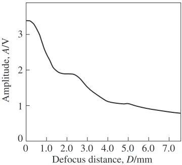
used for wave velocity measurement of a leaky SAW. However, when the V(z) curve method was applied to the rolling surface of bearings, a clear interference period was not observed, as shown in Fig. 1. This was attributed to the fact that the propagation distance of a leaky SAW did not
1 2 3
0
0 1.0 2.0 3.0 4.0 5.0 6.0 7.0 Defocus distance, D/mm
Amplitude,
A
/V
Fig. 1 V(z) curve measured in a deep groove ball bearing. Special Issue on Advances in Non-Destructive Inspection and Materials Evaluation
[image:1.595.337.517.604.767.2]vary linearly with the defocusing. It is reported that a V(z) curve with a clear interference obtained in a spherical surface such as a gyro bearing ball using near 400 MHz ultrasonic wave.5) However, we concluded that it was difficult to accurately measure the wave velocity along the rolling surface using the V(z) curve method at lower frequencies, and adopted a method6–8) in which the wave velocity is
directly measured from the propagation time of leaky SAW at a certain distance along the raceway surface of the bearings. Furthermore, a new type of focusing ultrasonic transducer was developed using piezoelectric copolymer films in order to measure the wave velocity in this method more accurately.
2. A New Type of Focusing Ultrasonic Transducer to Measure Leaky SAW Velocity in Bearings
2.1 Structure of the transducer
A leaky SAW can be generated on the surface of a test piece when the longitudinal wave is incident at the critical angle through water by defocusing a focusing ultrasonic transducer inside the sample.4)At this time, the leaky SAW
propagates on the surface, leaking longitudinal waves into the water. The longitudinal wave can be received by the same ultrasonic transducer. Generally, in order to generate SAW, a focusing ultrasonic transducer as shown in Fig. 2(a) is used.4,9)Inorganic piezoelectric materials such as PZT can be
effectively used in such transducers. This transducer has a problem in that multiple reflection waves occur in the acoustic lens. Moreover, both leaky SAW (1) and direct reflection waves (2) are received by the transducer simulta-neously, and an overlapping of leaky SAW with the direct reflection wave is observed. Since these waves interfere with each other, the transducer cannot receive only leaky SAW. In the adopted method, it is essential that only SAW be received by an ultrasonic transducer for measuring the wave velocity of SAW directly. Hence, we attempted to develop a new type of focusing ultrasonic transducer as shown in Fig. 2(b) by using a piezoelectric copolymer P(VDF-TrFE).10,11) The
aperture of the transducer was divided into three areas to detect the direct reflection wave and leaky SAW independ-ently.12) The advantage of this transducer is that the SAW
velocity in a partial region can be obtained because the direct reflection wave and leaky SAW can be measured separately at a short defocus distance. This transducer is hereafter referred to as a divided-type focusing ultrasonic transducer. It is possible to fabricate a focusing ultrasonic transducer without an acoustic lens by using a piezoelectric copolymer
because the material can be easily formed into a concave film.13)A divided-type focusing ultrasonic transducer can be
manufactured only by fabricating the electrode of each element on a piezoelectric copolymer film.14)In this
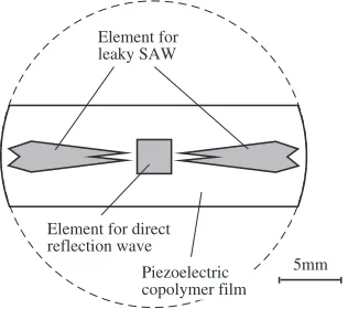
trans-ducer, the central element is for the direct reflection wave and the other two elements are for the leaky SAW. The direct reflection wave was used to measure the distance between the transducer and a test piece. Moreover, as shown in Fig. 3, the shape of the aperture for leaky SAW was designed so that the edge waves would be suppressed. Here, the shape of the aperture for leaky SAW is thin at the center of the transducer to make a leaky SAW propagate only along the race part of a deep groove ball bearing. The shape of the edge of the apertures was designed to make the edge waves scatter in different directions away from the focusing direction. More-over, the edge was designed so that the edge waves would negate each other in the range of the defocus position where wave velocity measurements would be performed.
2.2 Fabrication of divided-type focusing transducer Rolling fatigue will be expected to accumulate on the inner region of the raceway surface of deep groove ball bearings. Most of the energy of leaky SAW is distributed in a region having a depth less than one wavelength.15) Therefore, the
measurement has to be carried out with a lower frequency in order to propagate leaky SAW in as deep a region as possible from the race surface. The frequency characteristic of the ultrasonic transducer is affected by the thickness of the piezoelectric film and the acoustic impedance difference between the piezoelectric material and the backing material. Hence, in order to fabricate a transducer with a lower frequency characteristic, both a backing molded by epoxy resin with tungsten powder and a stacking of piezoelectric copolymer films were devised.
An epoxy resin and a composite material of epoxy resin and tungsten powder (mass ratio1 : 7:5) were used to prepare the backing material for the transducer. The acoustic impedance of the piezoelectric copolymer, epoxy resin, and composite material was approximately 4:6106kg/m2s, 2:9106kg/m2s, and 7:5106kg/m2s, respectively. In order to fabricate a divided-type focusing ultrasonic trans-ducer, the backing materials were first molded into a cylindrical shape, after which the bottom was molded into a concave shape by pressing with a steel ball before
Backing
(1) (2)
Piezoelectric film
Water
Sample (1)
(2)
Piezoelectric film
Water
Sample Backing
Acoustic lens
(b) Divided-type (a) Conventional
Fig. 2 Focusing ultrasonic transducer for leaky SAW.
5mm Element for
leaky SAW
Element for direct reflection wave
Piezoelectric copolymer film
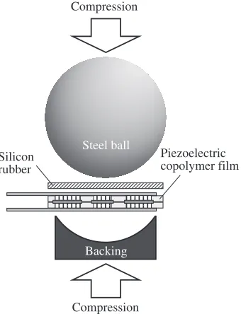
[image:2.595.349.507.73.213.2] [image:2.595.50.289.75.169.2]hardening. The size of the steel ball must be selected on the basis of the focal distance of the fabricated focusing transducer. In this study, in order to make a leaky SAW propagate on the raceway surface of a deep groove ball bearing with an outer diameter of 40 mm, the focal distance and the aperture angle of the transducer were set to 15 mm and 46, respectively. Therefore, a steel ball with a diameter
of 30 mm was used for the fabrication. After the 50-mm-thick piezoelectric copolymer films were formed by the casting method, the polarization of the films was carried out by using an electrode board made by a circuit board plotter, as shown in Fig. 4. Two polarized piezoelectric copolymer films were stacked using 6.5-mm-thick aluminum foil electrodes, as shown in Fig. 5, so that the polarization area might overlap correctly in the parallel stacking method.7)In this case, the area of the electrode has to be greater than that of the polarized region; however, only the polarized area functions as an ultrasonic element. The reason why this stacking method was adopted was because piezoelectric films stacked in parallel give a higher performance than the films stacked in series. An epoxy adhesive with a slow cure rate was used as glue in the stacking method. By gluing the stacked piezo-electric copolymer film to the prepared backing material with a concave surface, a divided-type focusing transducer was fabricated, as shown in Fig. 6. Finally, a support rod was attached to the backside of the backing material in order to operate the defocusing of this transducer with sufficient accuracy. At this time, the attachment work was carried out by using a special jig so that both the beam axis of the ultrasonic beam of the central element and the main axis of the rod might be aligned with each other.
2.3 Performance evaluation of divided-type focusing ultrasonic transducer
First, a comparison of the waveforms received by a non-divided-type and a non-divided-type focusing transducer at a defocus distance of approximately 1 mm was carried out by generating leaky SAW on a mild steel (SS400) block underwater. The focal length and the aperture of the non-divided-type focusing transducer are 15 mm and 3:0mm 10:0mm, respectively. In this experiment, focusing trans-ducers made of a piezoelectric copolymer with an epoxy resin backing were used. In the divided-type focusing transducer, the measurement was performed only using the elements for leaky SAW. The experimental result is shown in Fig. 7. Although leaky SAW and direct reflected waves were received simultaneously and their interference was observed in the non-divided-type focusing transducer (Fig. 7(a)), in the
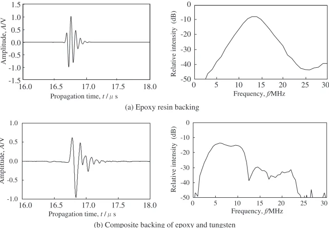
divided-type focusing transducer (Fig. 7(b)), it was verified that only leaky SAW could be received. Next, the effect of the treatment for suppressing edge waves was investigated. The measurements of SAW velocity by a divided-type focusing transducer with edge wave suppression treatment and by a divided-type focusing transducer without the treatment were carried out by using a mild steel plate. The latter transducer has two divided 2:0mm3:0mm elec-trodes instead of the elecelec-trodes used for leaky SAW in Fig. 3. The result is shown in Fig. 8. It was demonstrated that by conducting an edge wave suppression treatment, the meas-ured value of the SAW velocity settled from a shorter defocus position as compared to the case where the treatment was not conducted. Next, the received waveform and frequency spectrum of leaky SAW around a defocus distance of 2.5 mm obtained using a divided-type focusing transducer with the composite backing were compared with those obtained using a divided-type focusing transducer with an epoxy resin backing. The same mild steel block as the above experiment was used as the test piece for this experiment. In the results, the center frequencies of the transducers with an epoxy resin backing and composite backing were 13 MHz and 7 MHz, respectively (see Fig. 9). From the results, it was considered
Electrode Piezoelectric copolymer film
0.05Hz, 100MV/m Printed circuit board
Fig. 4 Polarization of piezoelectric copolymer films using the electrode board made by a circuit board plotter.
Piezoelectric copolymer film Electrode
Aluminum foil
Steel plate Compression
Compression Polarized
region
Fig. 5 Stacking of polarized piezoelectric copolymer films.
Steel ball
Silicon rubber
Backing
Compression Compression
Piezoelectric copolymer film
[image:3.595.85.250.73.155.2] [image:3.595.342.511.76.190.2] [image:3.595.343.513.237.459.2]that the transducer with epoxy resin backing, which has a smaller acoustic impedance than the piezoelectric element, vibrated with the 1/2 excitation mode. On the other hand, it was considered that the transducer with a composite backing vibrated with the 1/4 excitation mode because the acoustic
impedance of the backing material was sufficiently larger than that of the piezoelectric element. Since the transducer with a lower frequency characteristic provides a better impression of the rolling fatigue on the raceway surface of the bearing, the transducer with a composite backing was used for the evaluation of the rolling fatigue of deep groove ball bearings.
3. A Method for Calculating Leaky SAW Velocity on Deep Groove Ball Bearings Using the Divided-Type Focusing Transducer
It is difficult to estimate the distance from an element to the specimen in the propagation path accurately because the propagation path indicated by (1) in Fig. 2(b) varies with the defocus distance on the curvature surface. Therefore, the SAW velocity was calculated by the divided-type focusing transducer according to the following procedure. The SAW velocity on the inner ring of the bearing of radius R is measured, and each parameter required for the calculation is defined as shown in Fig. 10. From this figure, the following equations are obtained.
-3 -2 -1 0 1 2 3
18.0 18.2 18.4 18.6
Propagation time, t / s
-3 -2 -1 0 1 2 3
18.0 18.2 18.4 18.6
Propagation time, t / s
(b) Divided-type (a) Non-divided type
Amplitude,
A
/V
Amplitude,
A
/V
Fig. 7 Comparison of waveform received in about 1 mm defocus distance by a non-divided type focusing transducer and a divided-type focusing transducer. The aperture of the non-divided type is of3:0mm10:0mm area.
Defocus distance, D/mm
Wave velocity,
v
/ m
s-1
Fig. 8 Comparison of SAW velocity measured using a divided-type focusing transducer with edge wave suppression treatment and by using a divided-type focusing transducer without the treatment.
-1.0 -0.5 0.0 0.5 1.0
-50 -40 -30 -20 -10 0
0 10 15 20 25 30
Propagation time, t / s Frequency, f/MHz
Relative intensity (dB)
-1.5 -1.0 -0.5 0.0 0.5 1.0 1.5
(a) Epoxy resin backing 16.0 16.5 17.0 17.5 18.0
-50 -40 -30 -20 -10 0
0 10 15 20 25 30
Propagation time, t / s Frequency, f/MHz
Relative intensity (dB)
(b) Composite backing of epoxy and tungsten
Amplitude,
A
/V
Amplitude,
A
/V
16.0 16.5 17.0 17.5 18.0
5
5
[image:4.595.128.471.75.186.2] [image:4.595.79.262.242.375.2] [image:4.595.130.467.522.756.2]Rsin1¼K1sin1; ð1Þ
Rsin2¼K2sin2; ð2Þ
whereK1 andK2are defined as follows:
K1¼
ffiffiffiffiffiffiffiffiffiffiffiffiffiffiffiffiffiffiffiffiffiffiffiffiffiffiffiffiffiffiffiffiffiffiffiffiffiffiffiffiffiffiffiffiffiffiffiffiffiffiffiffiffiffiffiffiffiffiffiffiffiffiffiffiffiffiffiffiffi R22RðR
1Þcos1þ ðR1Þ2
q
ð3Þ
K2¼
ffiffiffiffiffiffiffiffiffiffiffiffiffiffiffiffiffiffiffiffiffiffiffiffiffiffiffiffiffiffiffiffiffiffiffiffiffiffiffiffiffiffiffiffiffiffiffiffiffiffiffiffiffiffiffiffiffiffiffiffiffiffiffiffiffiffiffiffiffi R22RðR
2Þcos2þ ðR2Þ2
q
: ð4Þ
From Snell’s law, we obtain the following:
sinð11Þ ¼
Cw Cs
; ð5Þ
sinð22Þ ¼
Cw
Cs
; ð6Þ
whereCwandCsare the longitudinal wave velocity in water and leaky SAW velocity, respectively. The difference between the propagation times of the leaky SAW elements at two defocus distances is given by
ta2ta1 ¼2
K1K2
Cw
þRð21Þ Cs
: ð7Þ
On the other hand, the difference between the propagation times of the direct reflection wave at the two defocus positions is given by
tb2tb1¼2
12
Cw
; ð8Þ
where1and2are the defocus distances at defocus position
1 and position 2, respectively. From the above equations,
Rcos2
K2
ffiffiffiffiffiffiffiffiffiffiffiffiffiffiffiffiffiffiffiffiffiffiffiffiffiffiffiffiffiffiffiffiffi
1 Rsin2 K2
2
s 0
@
1
ARð21Þsin2
Cwðta1ta2Þ
2 þ ðK1K2Þ ¼0 ð9Þ
is obtained. Further, from eq. (7),
Cs¼
Rð21Þ
ta2ta1
2 þ
K2K1
Cw
ð10Þ
is obtained. In order to calculateCs, we need to obtain the
values of1 and2 such that eq. (9) is satisfied. However,
these values cannot be obtained explicitly. Hence, the values of1and2 were determined by making them converge by
using a successive approximation method until the value of the left side of eq. (9) becomes less than109. By using these
calculated values, leaky SAW velocity on the bearings was calculated from eq. (10).
4. Rolling Fatigue Evaluation for Deep Groove Ball Bearings
The wave velocity of leaky SAW that was propagated on the raceway surface of the inner ring in 6206 (standardized in JIS B1513) deep groove ball bearings with an outer diameter of 40 mm was measured by using the developed divided-type focusing transducer. The wave velocity was calculated from eq. (10) by using the difference between the propagation time measured by setting the defocus distance to 2.0 mm and 3.5 mm by an immersion testing method.
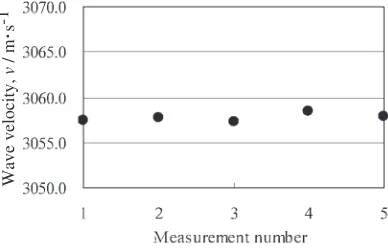
First, the repeatability of the measured value of leaky SAW velocity was examined. A new deep groove ball bearing was used as the sample. The transducer was attached to the sample only during every measurement, and the wave velocity was measured five times in the same region of the sample. The result is shown in Fig. 11. The averaged wave velocity was 3057.8 m/s, and the dispersion of the error was within 0.7 m/s. Therefore, it was verified that this method exhibited repeatability of wave velocity measurement.
Next, in order to investigate the individual differences in the leaky SAW velocity of new bearings, the wave velocity at four random points on two new bearings was measured. From the result of the measurement conducted twice at each point, it was observed that the average wave velocity of each bearing was in agreement and was approximately 3058 m/s in both the bearings. The dispersion range of the measured wave velocity in each bearing was 1.0 m/s or less, and it was verified that in new bearings there was almost no individual difference in the leaky SAW velocity.
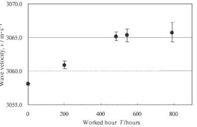
Finally, the wave velocity of leaky SAW was measured in the bearings whose worked hours differed. 6206 (stand-ardized in JIS B1513) deep groove ball bearings of five kinds were used as the samples. The worked hours of these bearings were 0 worked hour (new), 200 worked hours (equivalent to approximately 20% fatigue rate), 484 worked hours (equiv-alent to 60% fatigue rate), 542 worked hours, and 790 worked hours (both equivalent to over 90% fatigue rate). With the δ1
δ2 R Race surface
Divided-type focusing transducer
Inner ring of deep groove ball bearing α2
α1 β2
β1
[image:5.595.331.525.73.197.2]Center of the ring
Fig. 10 Definition of parameters in velocity measurement by the defocus-ing of a divided-type focusdefocus-ing transducer.
Wave velocity,
v
/ m
s-1
[image:5.595.72.267.73.250.2]exception of the new one, the samples had been prepared by working under a load of 11.7 kN using a radial-type rolling fatigue test machine. Measurements were conducted twice in four regions for each bearing. The results are shown in Fig. 12. The velocity increased with the worked hours of the bearings. This increase was attributed to the compressive plastic strain that was accumulated by the rolling fatigue. Average differences of the wave velocity of the new bearing were 2.9, 7.0, 7.2, and 7.7 m/s, respectively. The dispersion in the wave velocity increased according to the worked hours, while that of the bearing with 790 worked hours was the largest. This shows that rolling fatigue grows locally with the worked hour.
From the above results, it was demonstrated that the evaluation of the rolling fatigue of deep groove ball bearings would be possible from the wave velocity measurement of leaky SAW and that the developed divided-type focusing transducer was useful for this evaluation.
5. Conclusion
In order to receive leaky SAW without any interference by direct reflection waves, a new focusing ultrasonic transducer was developed. This transducer consists of three elements— one for the direct reflection wave and the other two for leaky SAW. Moreover, in order to suppress the effects due to the edge waves, the shape of the electrodes for leaky SAW was considered and its effect was verified. It was demonstrated that the transducer was able to measure the velocity of leaky SAW with accuracy within 0.7 m/s. A backing molded by
epoxy resin with tungsten powder and a stacking of piezo-electric copolymer films were devised as techniques to obtain a transducer with lower frequency characteristic. As a result, it was possible to fabricate a divided-type focusing trans-ducer with a center frequency of 7 MHz. This transtrans-ducer was used for rolling fatigue evaluation for the raceway surface in deep groove ball bearings. As a result of the wave velocity measurement of leaky SAW in deep groove ball bearings with worked hours from 0 to approximately 800, a difference of 2.9 to 7.7 m/s was obtained depending on the worked hour of the bearings. As mentioned above, it was demonstrated that the evaluation of the rolling fatigue in deep groove ball bearings would be sufficiently possible from the wave velocity measurement of leaky SAW by using the divided-type focusing transducer made of piezoelectric copolymer.
It is expected that with further developments in the technique, it will be possible to measure leaky SAW velocity without a defocus scan; this will be advantageous with respect to not only the inspection speed but also the cost.
REFERENCES
1) ISO 281:Dynamic load ratings and rating life for rolling bearings, 1990.
2) N. Oguma: KOYO Eng. J.161(2002) 26–31.
3) N. Oguma and T. Mikami: KOYO Eng. J.162(2002) 38–42. 4) J. David and N. Cheeke:Fundamentals and Applications of Ultrasonic
Waves, (CRC Press, USA, 2002) pp. 287–318. 5) R. D. Weglein: Appl. Phys. Lett.38-7(1981) 516–518. 6) K. Yamanaka: J. Appl. Phys.54-8(1983) 4323–4329.
7) I. Fujii, K. Kawashima and T. Sato: Trans. Jpn. Soc. Mech. Eng., Series
A63–615(1997) 2444–2448.
8) Lugen Wang: Ultrasonics37-4(1999) 283–289.
9) J. Hoffmann, S. Sathish, E. B. Shell, S. Fassbender and N. Meyendorf:
Nondestructive Materials Characterization, (Springer, Berlin, 2003) pp. 294–322.
10) H. Ohigashi and K. Koga: Jpn. J. Appl. Phys.21(1982) 455–457. 11) K. Koga and H. Ohigashi: J. Appl. Phys.56(1986) 2142–2150. 12) T. Onodera, A. Nakajima, T. Mihara and K. Yamanaka: Proc. of JSNDI
Spring Conference 2000, (The Japanese Society for Non-Destructive Inspection) pp. 211–212.
13) Y. Murata, T. Ogata and H. Toda: Proc. of the 6th Far East Conf. on Non-Destructive Testing, (The Japanese Society for Non-Destructive Inspection, 2002) pp. 135–140.
14) Y. Murata, Y. Tamura and K. Koyama: Acoustical Imaging20(1993) 379–386.
15) H. Kolsky:Stress Waves in Solid, (Dover Publications, 1963) pp. 16– 23.
Wave velocity,
v
/ m
[image:6.595.74.272.72.200.2]s-1