ISSN Online: 2164-3172 ISSN Print: 2164-3164
DOI: 10.4236/ojce.2018.84030 Nov. 5, 2018 426 Open Journal of Civil Engineering
Dynamic Analysis of Soil Structure Interaction
Effect on Multi Story RC Frame
Hailu Getachew Kabtamu
1, Gang Peng
2, Denghong Chen
3*College of Civil Engineering and Architecture, China Three Gorges University, Yichang, China
Abstract
In this study dynamic analysis of Soil Structure Interaction (SSI) effect on multi story reinforced concrete (RC) frame founded on soft soil (flexible base) is made and compared with fixed base. Two model 2D RC frames with 7 and 12 story are selected for analysis. Winkler Spring and half space direct method models are used for flexible base for the frames founded on two types of soft soils with shear velocity Vs < 150 m/s Asper Seismic Codes of Chinese GB50011-2010 Soil IV and Ethiopian ES8-2015 soil D. The frames are sub-jected to strong ground motion matched to response spectrums of soft soil of Chinese GB50011-2010 and Ethiopian ES8-2015 for linear time history analy-sis. The dynamic analysis result shows Spring and Fixed base mass participa-tion 90% reaches in 2 or 3 modes but in direct method 11 to 30 modes for story 12 and 7 respectively. However, both flexible base models have bigger fundamental period of vibration and inter story drift but smaller base shear than fixed base. In addition, within the flexible base models the inter-story drift, second order effect (P-Δ) and Story shear distribution are different along the height of frames. The spring model shows larger Story drift and second order effect (P-Δ) at the bottom of Story for both soft soils types. On the other hand, half space direct method model indicates value reverse to spring model; it gives bigger Story drift and P-Δ effect in the top stories than fixed base. Finally, this study concludes that base shear reduction due to SSI may not be always beneficial. Because the gravity load is constant in both fixed and flexible bases that cause bigger P-Δ effect at the bottom stories due to increase, inter story drift and decrease story shear in flexible base.
Keywords
Soil Structure Interaction, Dynamic Analysis, Fixed Base, Flexible Base, Direct Method, Winkler Spring, Period of Vibration, Story Shear, Story Drift and P-Δ Effect
How to cite this paper: Kabtamu, H.G., Peng, G. and Chen, D.H. (2018) Dynamic Analysis of Soil Structure Interaction Effect on Multi Story RC Frame. Open Journal of Civil Engineering, 8, 426-446.
https://doi.org/10.4236/ojce.2018.84030
Received: August 17, 2018 Accepted: November 2, 2018 Published: November 5, 2018
Copyright © 2018 by authors and Scientific Research Publishing Inc. This work is licensed under the Creative Commons Attribution International License (CC BY 4.0).
http://creativecommons.org/licenses/by/4.0/
DOI: 10.4236/ojce.2018.84030 427 Open Journal of Civil Engineering
1. Introduction
In dynamic analysis of a building structure, the base support condition is very essential for calculating its dynamic behavior useful in estimating structural res-ponses and distribution within structural members. The building base condition will be different depending on the type of supporting ground. Fixed base foun-dation could be assumed on stiff soil and flexible base founfoun-dation on soft soil. Flexibility of base causes decrease in structural stiffness and increase period of vibration during earthquake ground motion. Consequently, the building struc-tural responses such as displacement drift, Story shear, and P-∆ effects will be different from fixed base that could beneficial or detrimental. As a result, in the past the dynamic analysis building on soft soil has gained serious attention in seismic active areas.
[image:2.595.266.479.523.685.2]Wolf 1985 [1] and many other authors noted that for structures built on strong foundation such as rock during earthquake motion, the force generated in the form of overturning moment and transfers shear will not cause deforma-tion to the base in turn; the stiffness of structure remains constant. For a given control of motion, the seismic response of the structure depends only on the properties of the structure, however for soft soils used as base; the base deforma-tion changes the stiffness of structure during earthquake vibradeforma-tion, which in turn affects its response, known as Soil Structure Interaction (SSI) effect. Even if, SSI has both kinematic and inertia effect on structure; in this study only inertia ef-fect is considered.
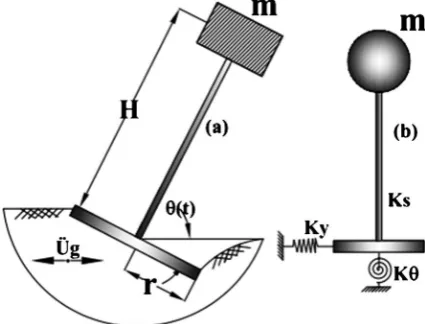
Figure 1 illustrates SSI effect on structures [2]. For single mass (m), height (H), stiffness (Ks) supported on soft soil foundation lateral stiffness (Ky), and ro-tational stiffness (Kθ) foundation base radius (r) subjected to ground motion ac-celeration üg. This causes the base deformation in rotation (θ) and larger transla-tion of at the top of structure that results base flexibility (SSI). Consequently, the dynamic behavior of the structure changes affected structural responses like pe-riod of vibration, displacement, base shear, and secondary moment effects P-Δ
DOI: 10.4236/ojce.2018.84030 428 Open Journal of Civil Engineering (mainly axial load carrying vertical members such as column in multi-story building).
In the past, many studies showed that soil structure interaction (SSI) has both beneficial and detrimental effect on structure. Because SSI increases flexibility of structure, lengthening of structural vibration period and damping. As a result, in building structures, the base shear decreases; however at the same time dis-placement increases. The decrease in base shear may be advantages, but the crement in displacement induces secondary moments P-∆ effect due to high in-ter-story drift. Moreover, excessive deflection of building could lead to collision of nearby structures. In addition, P-∆ is highly emphasized structural members supporting big axial load such as tall building, and consequence can be cata-strophic which leads to instability of the whole structure. Moreover, there are researches those stating that for some special cases fixed base models can lead to an underestimation of seismic response [3] [4] [5]. According to references [4], the idea of design spectra of the seismic codes along with the increased funda-mental period and effective damping due to SSI lead always to reduce forces in the structure is not always true. It is shown that in certain seismic and soil envi-ronments, an increase in the fundamental natural period of a moderately flexible structure due to SSI may have detrimental effect on the imposed seismic demand [4] [6]. In contrast [7] study emphasizes the beneficial effect of soil structure teraction for reduction of seismic demand as economic advantage without in-cluding the P-∆ effect that may lead to catastrophic failure.
Additionally, the SSI effect has been included in some seismic codes. Euro-pean regulation for seismic design Eurocode 8 (EC8-2004) [8] of structures from which Ethiopia Seismic Standard Code (ES8-2015) [9] adopted from contains very few information for including Soil-Structure Interaction. Seismic design of foundation regulation EN1998-Part 5 Extension of EC8-2004 [10] states that SSI the fundamental period of vibration of the flexibly-supported structure will be longer than that of the fixed-base structure, the overall damping will increase both due to radiation and the internal damping generated at the soil-foundation interface, in addition to the damping associated with the superstructure. EN1998-Part 5 [10] states for the majority of common building structures, the effects of SSI tend to be beneficial, since it reduce the bending moments and shear forces in the various members of the superstructure. Nevertheless, EN1998-Part 5 [10] noted also the effect of SSI structures supported on soft soils shear velocity Vs < 100 m/s can have detrimental effect on structures where P-∆ (2nd order) effects play a significant role; structures with massive or; slender tall structures, such as towers and chimneys.
DOI: 10.4236/ojce.2018.84030 429 Open Journal of Civil Engineering structural response analysis does not directly incorporate the effects of founda-tion flexibility. For equivalent lateral force procedure fulfilling requirement, to account for the effects of soil-structure interaction, the base shear (V) deter-mined from shall be reduced to V in Equations (1) and (2)
V V= − ∆V (1) The reduction ΔV, shall be computed as follows and shall not exceed 0.3 V
0.4
0.05 0.3
s s
V C C W V
β ∆ = − ≤
(2)
where Cs = the seismic design coefficient computed from Equations 12.8-2, 12.8-3 calculated using fixed base fundamental period of vibration (T) and
C
s = the value of Cs computed from Equations 12.8-2, 12.8-3 calculated using flexi-bly supported structure (T
) in ASCE/SEI 7-10 Section 12.8.β
= the fraction of critical damping for structure-foundation system.W
= the effective seismic weight of structure which shall be taken as 0.7 W, except for structures where effective weight is concentrated at a single level, tak-en as equal to W.The effective period
T
shall be determined as follows in Equation (3) 21 1 y
y
K h k
T T
K Kθ
= + +
(3)
where T = the fundamental period of the structure as determined in 12.8.2 of ASCE7-10.
k = the stiffness of the structure where the fixed base, defined by Equation (4)
2 2
4π W
k
gT
=
(4) where, h = the effective height of the structure, which shall be taken as 0.7 times the structural height (hn) except for structures where gravity load is con-centrated at a single level, equal to that level.
Ky = the lateral stiffness of the foundation as the horizontal force at level of the foundation necessary to produce a unit deflection at that level, the force and deflection being measured in the direction in which the structure is analyzed.
Kθ = the rocking stiffness of the foundation defined as the moment necessary to produce a unit average rotation of the foundation, the moment and the rota-tion being measured in the direcrota-tion in which the structure is analyzed.
g = acceleration due to gravity.
Effective damping factor for structures foundation system
β
shall be com-puted by Equation (5)0 3
0.05 T T
β β=
DOI: 10.4236/ojce.2018.84030 430 Open Journal of Civil Engineering
β0 = the foundation damping factor as specified in Figure 2 that shows damping factor increase up to 20% for period of vibration lengthening factor of 1.5 to 2.0 compared with fixed base.
Similar to EC8-2004 Part 5 and ASCE/SEI 7-10,Chinese seismic code GB 50011-2010 [12] considers Soil Structure Interaction effect according to Article 5.2.7, horizontal seismic shear force of rigid base may be reduced according to requirements and Story drift may be calculated according to reduced story shear force, however not detailed enough. In conclusion, the three seismic codes do not provide full recommendation, which requires further study.
So far, several SSI study on building report mainly focuses only on period of vibration, displacement, story drift, story shear and geotechnical parameters that affects SSI biased to geotechnical engineering. However, little attention is given to structural responses such as P-∆ effect due to gravity load of building itself affecting vertical structural members for example column, even if many building collapsed as a result of P-∆ secondary moments and instability. In this paper SSI effect (flexible base) on P-∆ effect is additionally studied using two methods: half space direct method of soil structure interaction, and Winkler Spring and then compared with fixed base using SAP2000 structural analysis software [13] for 2D reinforced concrete frame. In addition, soil-structure interaction (SSI) effect responses variation along height of building among fixed and flexible bases is studied.
2. Model Structural System for SSI Analysis
2.1. Structural System and Soil Data
[image:5.595.260.487.476.699.2]For comparative analysis of fixed base and flexible base structures, two residential buildings frame regular in plan and elevation are considered to avoid secondary
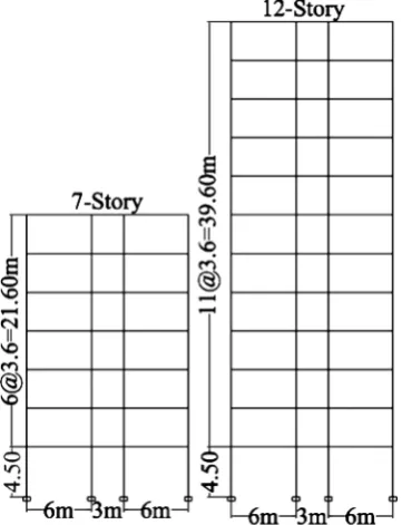
DOI: 10.4236/ojce.2018.84030 431 Open Journal of Civil Engineering effects due to irregularity. Figure 3 shows the same typical residential buildings plan of 15 m × 32 m for both model frames common Architectural plan in China that can be adopted to Ethiopian construction. The plan is adapted from Chinese Seismic and Concrete Design standards [14] [15] and modified for this study purpose. The 2D model frames here after denoted as, S7 and S12 for 7 and 12-story respectively. Figure 4 shows typical transverse frames S7 and S12 story with first story height 4.50 m and others typical Story height of 3.6 m. The frames are considered in the short transfer direction and carry tributary area of floor load shown in Figure 3 for 2D regular frame analysis. The columns and beams of frames are designed according to Ethiopian Concrete Design Standard ES2-2015 [16] that are subjected to design seismic action of PGA = 0.25 g soil type B design response spectrum [9]. Beam sections for both model frame are the same BM 25 cm × 65 cm, but column sizes are different, CL65 cm × 65 cm
Figure 3. Typical floor plan for model residential building S7 and S12.
[image:6.595.284.465.460.696.2]DOI: 10.4236/ojce.2018.84030 432 Open Journal of Civil Engineering for S7 and CL70 cm × 70 cm for S12. Furthermore, the beam and column stiff-ness in the frame are proportioned to behave in shear mode according to [17].
In seismic weight calculation, given imposed load on residential building, according to ES1-2015 [18] and GB5009-2012 [19], Uniform Live Load LL = 2.0 kN/m2, Roof live load LL = 1.0 kN/m2 and dead load floor finish and other walls including self-weight is 8.30 kN/m2, and wall load on beam including self-weight of beam is 15.90 kN/m. For seismic weight calculation, GB50011-2010 is used 50% of live load and 100% dead load for dynamic analy-sis. Total dead load transferred on floor beam using tributary area including self-weight is 55.00 kN/m and roof floor beam is 37.28 kN/m for analysis. Live load transferred on floor beam 8.00 kN/m and 4.00 kN/m on roof beam.
Structural members material strength specifications from [16] [20]: Con-crete C-30, Ec = 31 × 106 kN/m2, Concrete Unit Weight = 24 kN/m3 and Steel S-400/HRB400, Es = 200 × 106 kN/m2, Steel Unit Weight = 78.5 kN/m3.
Soil properties supporting the structure: Assumed soft soil category ac-cording to GB50011-2010 and ES8-2015 for depth greater than 30 m below the structure Shear Velocity Vs = 150 m/s corresponds to soil D in ES8-2015 [9] and Soil IV in GB50011-2010 [12], Density ρ = 1500.00 kg/m3, Poisson Ratio, ν = 0.40, Shear modulus, G = 33.75 Mpa, and Elastic modulus, E = 94.50 Mpa.
2.2. Soil Structure Interaction Numerical Modelling
To date, many general-purpose structural analysis softwares are available for modelling structural members with well-defined member properties and boun-daries of structures in either 3D or 2D analysis. However, Soil Structure Interac-tion (SSI) analysis model involves both structural member and foundaInterac-tion soil properties, which does not have well defined engineering material properties and boundaries. Because of this many simulation software’s may be suggested for soil structure interaction analysis but may not be suitable in design office for practice [2]. In this study general-purpose structural analysis software SAP2000 [13] is selected that is commonly available in design offices and that has capacity to si-mulate SSI [21].
ri-DOI: 10.4236/ojce.2018.84030 433 Open Journal of Civil Engineering gid following the longer distance, an equivalent plane-strain foundation-soil model is valid [30]. In the same way in this study, for the regular model building both in plan and in elevation considered above, 2D frame for SSI analysis is used.SSI is modelled using direct half space method and Winkler Spring. Finally, the structural responses of SSI are compared with fixed base.
2.2.1. Direct Half Space Method
Most structural analysis computer programs including SAP2000, chosen for this study, automatically apply the seismic loading to all mass degrees of freedom within the computer model and cannot solve the SSI problem. However, this can be solved using the most common soil-structure interaction (SSI) approach, used three dimensional soil-structure systems, is based on the ‘‘added motion’’ formulation [21]. This formulation is mathematically simple, theoretically cor-rect, and is easy to automate and use within a general linear structural analysis program SAP2000 [21], which is based on modelling SSI with massless founda-tion. Therefore, in the added mass formulation, the entire structure and soil can be modelled in single system defined as direct method of SSI analysis. The base soil is modelled using half space model with dimensions defined according to [22]. If the soil material can be considered linear, the SAP2000 program, using the Solid element, can calculate either the one-, two- or three-dimensional free-field motions at the base of a structure [21]. In this study Linear time histo-ry analysis is made using finite element based structural analysis software SAP2000 [13]. 2D reinforced concrete frame analysis is made without non cracked beam and column stiffness subjected to Matched Loma Prieta earth-quake with magnitude-6.9 in 1989 [31].
DOI: 10.4236/ojce.2018.84030 434 Open Journal of Civil Engineering normal and tangential direction adapted from [34] [35] in Equations (6a) to (6f)
BN , BN p
b
AG
K C AV
r
ρ
= = (6a)
BT 2 , BT S
b
AG
K C AV
r
ρ
= = (6b)
p M
V
ρ
= , P-Wave Velocity
(6c)
s G
V
ρ
= , Shear wave Velocity (S-Wave) (6d)
(
)
2 1
E
G= ν
+ , Shear Modulus (6e)
(
)
(
1)(
11 2)
E
M ν
ν ν
− =
+ − , P wave Modulus
(6f)
where KBN and KBT are the normal and tangential stiffness coefficients, respec-tively. CBN and CBT are the normal and tangential damping coefficients, respec-tively. A is the total area of all elements around the node at the boundary. rb is the distance from the scattering wave source to the artificial boundary point. Vs and Vp are the wave velocities of the S wave and P wave, respectively. G is the medium’s shear modulus, E—Elastic modulus, ν—Poisson ratio and ρ is the medium’s mass density.
Given Soft Soil Properties above;
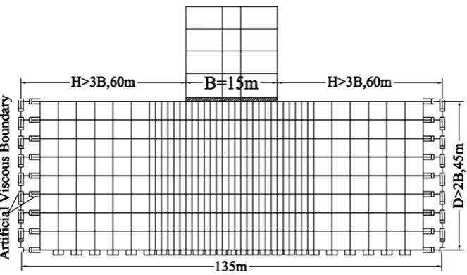
[image:9.595.209.541.499.694.2]ρ = 1500.00 kg/m3, ν = 0.40, G = 33.75 Mpa, E = 94.50 Mpa, Vs = 150 m/s, then, Vp = 367.42 m/s, KBN = 2250.0 kN/m, KBT = 1125.0 kN/m, CBN = 1653.0 kN∙s/m and CBT = 675.0 kN∙s/m. This values are used for modelling viscous spring dashpot in SAP2000 [13] using link support element at the half space boundary model of direct method shown in Figure 5.
DOI: 10.4236/ojce.2018.84030 435 Open Journal of Civil Engineering
2.2.2. Winkler Spring Method
In addition to the direct method of modelling, for evaluating the seismic re-sponse of reinforced concrete multi-story buildings with raft foundation on soft soil, the underneath soil is modeled by Winkler spring approach with equivalent static stiffness based on soil modulus of elasticity [3] [27]. For same soft soil used in direct method with shear velocity of Vs = 150 m/s., equivalent static stiffness for different direction vibration mode, the soil spring stiffness can be calculated using Gazetas 1991 [36] expressions shown in Equations (7a) to (7c).
Vertical direction (Z)
(
)
0.75 0.73 1.54 1
z GL B
K
L
ν
= +
− (7a)
Horizontal (lateral direction y)
(
)
2.0 2.50 0.85 2y GL B
K
L
ν
= +
− (7b)
Horizontal (Longitudinal direction x)
(
0.2)
1 0.75x y GL B
K K
L
ν
= − −
− (7c)
where G is shear modulus of soil defined in Equation 6(e), E is the modulus of elasticity of soil; ν is the Poisson’s ratio of soil. L and B are the length and width of Raft foundation of the whole building, respectively. For Raft foundation plan Length L = 32 m and Width B = 15 m, Soft soil with shear velocity Vs = 150 m/s, Poisson ratio ν = 0.4, Shear Modulus G = 33.75 Mpa, Modulus of Elasticity E = 94.50 Mpa, Dynamic stiffness in the vertical direction, Kz = 6.00 × 10³ (kN/m2)/m, Horizontal in lateral direction Ky = 4.66 × 10³ (kN/m2)/m, Horizontal Longitu-dinal direction Kx = 3.98 × 10⁶ (kN/m2) /m. For 2D frame analysis, the total stiffness of raft is distributed to each column support according to its tributary area.
3. Earthquake Loading
In this study strong ground motion Loma Prieta 1989 from PEER [31] is matched to design response spectrum of soft ground type of Ethiopian Seismic Code and Chinese with shear velocity Vs = 150 m/s, which is used for time his-tory analysis of 2D frame in S7 and S12 model building.
3.1. Design Response Spectrum
DOI: 10.4236/ojce.2018.84030 436 Open Journal of Civil Engineering
3.2. Matched Strong Ground Motion
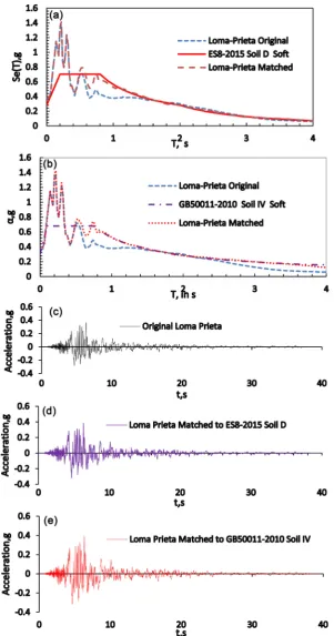
For dynamic analysis, strong ground motion of Loma Prieta earthquake of USA in 1989ground motions, PGA = 0.367 g is used [31]. To use ground motion for analysis, matching to the design response spectrum with 5% damping is needed. For matching, procedures outlined in Seismic Code of Ethiopia ES8-2015 [9] are used. The ground motion is matched to equivalent target response spectrum of very soft ground type D of ES8-2015 PGA = 0.25 g and IV of GB50011-2010 PGA = 0.3 g. Seismosmatch 2016 is used for matching [39], a computer program to adjust ground-motion records so that their spectral acceleration response matches a target response spectrum. For matching ES8-2015 recommends 0.2T1 and 2T1 minimum and maximum for specific building structure, where T1 fun-damental period of vibration, using modal analysis in SAP2000 with fixed base model the fundamental period of vibration. In this study 12 Story frame with fundamental period of vibration T1 = 2.12 s is used. Accordingly, the matching pe-riod for Loma Prieta earthquake is Tmin = 0.424 s and Tmax = 4.0 s. Table 1 and Figures 7(a)-(e) show matched ground motion parameters for the two design response spectrums.
3.3. Time History Analysis
Using the matched strong ground motion linear time history analysis is made for flexible and fixed base support conditions of the frames Story 7 (S7) and Story 12 (S12). For all support conditions, the seismic responses are calculated using SAP2000 structural analysis software [13].
4. Results and Discussion
[image:11.595.237.510.479.598.2]This section presents the dynamic analysis results. This includes dynamic properties
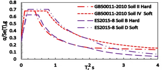
[image:11.595.212.539.649.717.2]Figure 6. Equivalent design response spectrum of GB50011-2010 and ES8-2015.
Table 1. Original and matched ground motion loma prieta earthquake.
DOI: 10.4236/ojce.2018.84030 437 Open Journal of Civil Engineering
DOI: 10.4236/ojce.2018.84030 438 Open Journal of Civil Engineering and other response of the model structures S7 and S12 shown in table and graph form. All response comparisons are made with reference to fixed base for both types of flexible base models presented in subsequent sections.
4.1. Modal Analysis Result
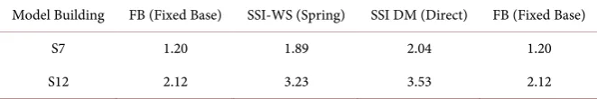
Modal analysis of the model frames S7 and S12, both fixed and flexible base (SSI), is made using finite element method software, SAP2000 [13]. Flexible base is modelled using the two methods Winkler (SSI WS) and direct method half space method (SSI DM). From the analysis result, mass participation of frames 90% or more reaches with few modes of 2 or 3 in both Spring and Fixed base. On the other hand, in direct method from 11 to 30 modes is required, which corres-ponds to S12 and S7 frames respectively. This shows higher mode effect is more important in direct method modelling of SSI, which in turn affects the structural responses of frames. Furthermore, the fundamental period of structures with flexible base of SSI-WS and SSI-DM is greater than FB shown in Table 2, for S7 SSI-WS and SSI-DM and greater than FB by 57.50% and 70.00% respectively, in addition, for S12 SSI-WS and SSI-DM greater by 52.00% and 66.50% respectively. The period lengthening shows good agreement with ASCE Standard ASCE/SEI 7 - 10 provisions [11].
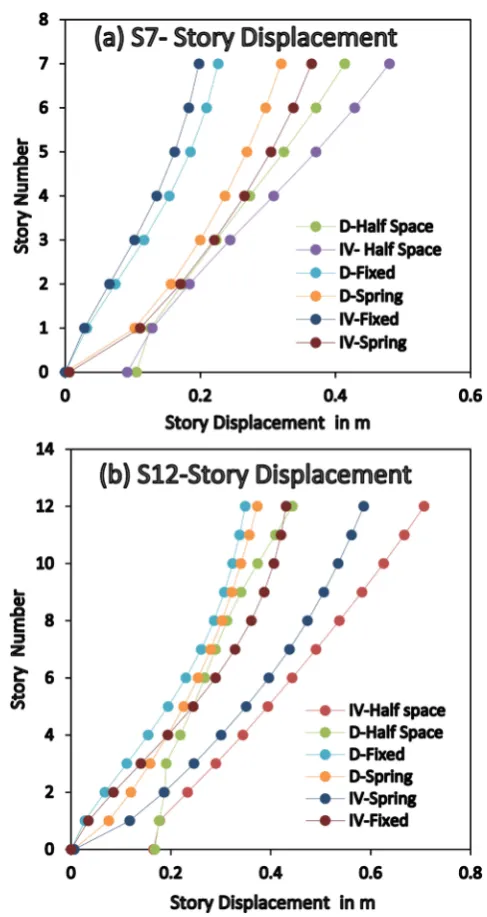
4.2. Story Displacement
Story displacement is very essential parameters for nearby building collision ef-fect in seismic event for making enough separation between nearby structures. The deflection profile is different based on fixity of the base. Figure 8(a) and Figure 8(b) show the displacement difference in fixed and flexible base. The top Story displacement of flexible base is greater than the fixed base by 143% in S7 and 189% in S12 for soil IV in Half space Model. For spring model soil IV, 185% in S7 and 162% in S12.Similar pattern for soil D is shown in Figure 8(a) and Figure 8(b).
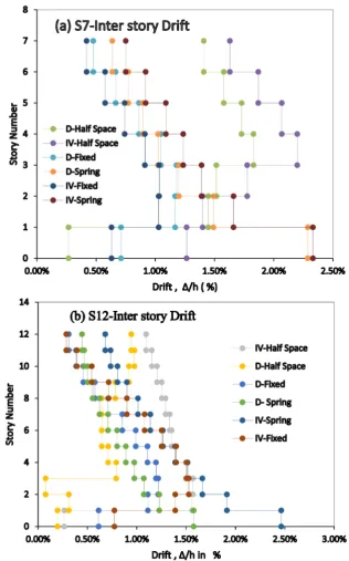
4.3. Inter Story Drifts
[image:13.595.207.538.660.715.2]Story drift is one of the important parameter for lateral load effect on vertical members in stability analysis. Figure 9 shows the Story drift in flexible base compared with fixed base. Figure 9(a) compared to fixed base S7 inter Story drift for Half Space Model SSI-DM, soil D 38% to 295% bottom to top stories and for soil IV 200% to 388%, increasing trend bottom to top. For spring model, however soil D 322% to 134% bottom to top stories and for soil IV 370% to
Table 2. Fundamental period of vibration T1 flexible and fixed base.
Model Building FB (Fixed Base) SSI-WS (Spring) SSI DM (Direct) FB (Fixed Base)
S7 1.20 1.89 2.04 1.20
DOI: 10.4236/ojce.2018.84030 439 Open Journal of Civil Engineering
Figure 8. Story Displacement of S7 (a) and S12 (b).
179%, decreasing trend. Similarly, Figure 9(b) shows compared to fixed base S12 inter Story drift for Half Space Model SSI-DM, soil D 32% to 304% bottom to top stories and for soil IV 34% to 382%, increasing trend bottom to top. For spring model, however soil D 257% to 143% bottom to top stories and for soil IV 319% to 238%, decreasing trend.
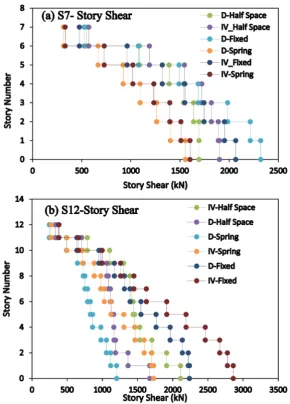
4.4 Story Shear
DOI: 10.4236/ojce.2018.84030 440 Open Journal of Civil Engineering
Figure 9. Story Drift (a) S7 and (b) S12.
bottom and top stories respectively. Similarly soil IV, 92% and 120% of fixed base in bottom and top stories. On the other hand, spring model for soil D varies 67% to 60% bottom to top and the same trend for soil IV 77% to 70% bottom to top stories of fixed base model decreasing trend.
DOI: 10.4236/ojce.2018.84030 441 Open Journal of Civil Engineering
Figure 10. Story Shear (a) S7 and (b) S12.
Spring model for soil D varies 53% to 76% bottom to top and the same trend for soil IV 60% to 75% bottom to top stories of fixed base model increasing trend compared to S7. This shows, the decreasing effect is not always true for mul-ti-Story building.
4.5. P Delta Effect
DOI: 10.4236/ojce.2018.84030 442 Open Journal of Civil Engineering effect of change in base fixity is noted in the ratio of story drift to storey shear (Δ/Vtot). This effect can be shown in Figure 12(a) and Figure 12(b) for S7 and S12.
Figure 11. P-delta effect on column.
[image:17.595.219.527.259.687.2]DOI: 10.4236/ojce.2018.84030 443 Open Journal of Civil Engineering 0.10
tot
tot
P V h
θ= ⋅ ∆≤
⋅ (8)
where
θ is the inter Story drift sensitivity coefficient;
Ptot is the total gravity load at and above the Story considered in the seismic design situation;
Δ is the design inter story drift, evaluated as the difference of the average lat-eral displacements dsat the top and bottom of the Story under consideration and calculated in accordance with 4.3.4 of ES8-2015 [9];
Vtot is the total seismic Story shear; and h is the inter story height.
Figure 12(a) and Figure 12(b) show sensitivity coefficient of flexible base and fixed base. (Figure 12(a)) S7 for soil D SSI-DM sensitivity coefficient θ is 52% and 284% of fixed base sensitivity coefficient at the bottom and top Story respec-tively. On the other hand, for soil IV, 218% and 324% for the corresponding sto-ries in direct method. Furthermore, for soil D spring model the sensitivity coef-ficient can be 481% and 223% bottom and top stories respectively. On the other hand, for soil IV spring model it is 477% and 256% bottom and top Story.
In addition, Figure 12(b) shows, for S12 the things are somewhat different than S7, for half space model SSI-DM soil D sensitivity coefficient θ is 56% and 148% of fixed base in bottom and top Story respectively, that shows P delta effect smaller bottom Story. Nevertheless, for soil IV it is different case, 143% and 341% greater than fixed base, bottom and top Story respectively. In both soils, P delta effect tends to decrease at bottom Story than top, however soil D is far more small, effect of response spectrum ES8-2015 and while IV, response spectrum GB50011-2010. For SSI-WS, spring model with soil D for S12 sensitivity coeffi-cient θ is 478% and 220% of fixed base in bottom and top Story respectively. On the other hand, soil IV it is 659% and 337% greater than fixed base, bottom and top Story respectively. This shows both spring as well as half space models have their own advantage and disadvantage in SSI modelling.
5. Conclusions
DOI: 10.4236/ojce.2018.84030 444 Open Journal of Civil Engineering mass participation factor of 90% than spring model.
In addition, closer examination of spring model of ground motion effects of D and IV on model frames S7 and S12 is different. The smaller ground motion with soil D gives bigger story drift, P-delta effect and Story shear on S7 than S12 while larger ground motion with Soil IV shows the opposite. This indicates big-ger earthquake effect more on taller than short building. Because soil IV ground motion (Chinese GB50011-2010) is greater than soil D (Ethiopian ES8-2015), which is related to the design response spectrum of the corresponding seismic codes magnitude.
To sum up, SSI effect may not be always beneficial in multi-story RC frame compared to fixed base. Because the beneficial effect reduction in base shear may be smaller than detrimental effect of P-delta increment on vertical load carrying members. The results obtained in this study is limited to linear time history analysis regular 2D RC frame; however it is good indicator of SSI effect; further study can be made in future to take non linearity effect both in structure and soil.
Acknowledgements
The first Author thanks China Scholarship Council (CSC) for sponsoring this study in China Three Gorges University. In addition, all references and soft-wares used from different sources are duly acknowledged.
Conflicts of Interest
The authors declare no conflicts of interest regarding the publication of this paper.
References
[1] Wolf, J.P. (1985) Dynamic Soil Structure Interaction.
[2] Livaoglua, R. and Dogangun, A. (2006) Simplified Seismic Analysis Procedures for Elevated Tanks Considering Fluid-Structure-Soil Interaction. Journal of Fluids and Structures, 22, 421-439.https://doi.org/10.1016/j.jfluidstructs.2005.12.004
[3] Kraus, I. and Džakić, D. (2013) Soil-Structure Interaction Effects on Seismic Beha-viour of Reinforced Concrete Frames. SE-50EEE, International Conference on Earthquake Engineering, Skopje, 29-31 May 2013, Paper Number: 645073.
https://bib.irb.hr/prikazi-rad?&lang=EN
[4] Mylonakis, G. and Gazetas, G. (2000) Seismic Soil Structure Interaction: Beneficial or Deterimental? Journal of Earthquake Engineering,4, 277-301.
https://doi.org/10.1080/13632460009350372
[5] Behzad, F., Reza, T.S.H. and Bijan, S. (2014) Soil-Structure Interaction vs Site Effect for Seismic Design of Tall Buildings on Soft Soil. Geomechanics and Engineering, 6, 293-320.https://doi.org/10.12989/gae.2014.6.3.293
[6] Tabatabaiefar, H.R. and Clifton, T. (2016) Significance of Considering Soil-Structure Interaction Effects on Seismic Design of Unbraced Building Frames Resting on Soft Soils. Australian Geomechanics, 51, 55-64.
DOI: 10.4236/ojce.2018.84030 445 Open Journal of Civil Engineering
for Economical Seismic Design of Buildings? Journal of the South African Institu-tion of Civil Engineering, 56, 54-62.
[8] Eurocode 8 EN1998-1 (2004) Design of Structures for Earthquake Resistance, Part 1: General Rules, Seismic Actions and Rules for Buildings. Brussels.
[9] ES8-2015 (2015) Ethiopian Standard 8 Based European Norms; Design of Earth-quake Structures for EarthEarth-quake Resistance, Part 1: General Rules, Seismic Actions and Rules for Buildings. Ethiopia Ministry of Construction, Addis Ababa.
[10] Eurocode 8 EN1998-5 (2004) Design of Structures for Earthquake Resistance, Part 5: Foundations, Retaining Structures and Geotechnical Aspects. EN1998-5, Brussels. [11] ASCE/SEI 7-10 American Society of Civil Engineers (2010) Minimum Design Loads
for Buildings and Other Structures.
[12] GB50011-2010 (2010) China Code for Seismic Design of Buildings. China Archi-tecture & Building Press, Beijing.
[13] CSI (2009) Structural Analysis Program SAP2000 Advanced 14.0.0. Computers and Structures, Inc., Berkley.
[14] Zhao, W.X.L., Sheng, C.L., Hui, Q. and Le, L. (2015) Reinforced Concrete Funda-mentals according to Chinese Building Code GB50010-2010. China building Indus-try Press, Beijing.
[15] Ling, L.X., Yuan, Z.D., Ming, L.S. and Liang, L.H. (2011) Seismic Design Theory and Example of Building Structure. Tongji University Press,Shanghai.
[16] ES2-2015 (2015) Ethiopian Standard 2 Based on European Norme: Design of Con-crete Structures: Part 1-1: General Rules and Rules for Buildings.Ethiopia Ministry of Construction, Addis Ababa.
[17] Sinan Akkar, U.Y. and Gülkan, P. (2005) Drift Estimates in Frame Buildings Sub-jected to Near-Fault Ground Motions. Journal of Structural Engineering, 131, 1014-1024.https://doi.org/10.1061/(ASCE)0733-9445(2005)131:7(1014)
[18] ES1-2015 (2015) Ethiopian Standard 1 Based on European Norms: Actions on Structures—Part 1-1: General Actions-Densities, Selfweight, Imposed Loads for Buildings. Ethiopia Ministry of Construction, Addis Ababa.
[19] GB50009-2012 (2012) Load Code for the Design of Building Structures. China Building Industry Press.
[20] GB50010-2010 (2010) China Code for Concrete Design of Structures. China Archi-tecture & Building Press, Beijing.
[21] Wilson, E.L. (2002) Three-Dimensional Static and Dynamic Analysis of Structures a Physical Approach with Emphasis on Earthquake Engineering. Computers and Structures, Berkeley.
[22] Tabatabaiefar, H.R. and Massumi, A. (2010) A Simplified Method to Determine Seismic Responses of Reinforced Concrete Moment Resisting Building Frames un-der Influence of Soil-Structure Interaction. Soil Dynamics and Earthquake Engi-neering, 30, 1259-1269.https://doi.org/10.1016/j.soildyn.2010.05.008
[23] Sáez, E., Lopez-Caballero, F. and Modaressi-Farahmand-Razavi, A. (2013) Inelastic Dynamic Soil-Structure Interaction Effects on Moment-Resisting Frame Buildings.
Engineering Structures, 51, 166-177.
https://doi.org/10.1016/j.engstruct.2013.01.020
[24] Lu, X.-Z., Ye, L.-P., Ma, Y.-H. and Tang, D.-Y. (2011) Lessons from the Collapse of Typical RC Frames in Xuankou School during the Great Wenchuan Earthquake.
DOI: 10.4236/ojce.2018.84030 446 Open Journal of Civil Engineering
[25] Manafpour, A. R. and Moradi, V. (2012) Investigating Conventional FE Modelling for Dynamic Soil-Structure Interaction under Horizontal and Vertical Ground Mo-tions. Proceedings of the 15th World Conference on Earthquake Engineering, Lis-bon, 24-28 September 2012, 20147-20157.
[26] Petronijevic, P., Zdravkovic, S., Mdladnovic, B., Zlatkov, D. and Petronijevic, A.M. (2014) Analysis of a Potential Collision of Building Earthquake Based Computer Simulation. Tehnicki Vjesnik, 21, 1125-1133.
[27] Raheem, S.E.A., Ahmed, M.M. and Alazrak, T.M.A. (2015) Evaluation of Soil-Foundation-Structure Interaction Effects on Seismic Response Demands of Multi-Story MRF Buildings on Raft Foundations. International Journal Advanced Structural Engineering, 7, 11-30.https://doi.org/10.1007/s40091-014-0078-x
[28] Karabork, T. and Bilgehan, R.P. (2014) A Comparison of the Effect of SSI on Base Isolation Systems and Fixed-Base Structures for Soft Soil. Geomechanics and Engi-neering, 7, 87-103.https://doi.org/10.12989/gae.2014.7.1.087
[29] Güllü, H. and Pala, M. (2014) On the Resonance Effect by Dynamic Soil-Structure Interaction: A Revelation Study. Natural Hazards, 72, 827-847.
https://doi.org/10.1007/s11069-014-1039-1
[30] Saez, E., Lopez-Caballero, F. and Modaressi-Farahmand-Razavi, A. (2008) Influence of 2D and 3D Soil Modeling on Dynamic Nonlinear SSI Response. The 14th World Conference on Earthquake Engineering, Beijing, 12-17 October 2008, Paper ID: 14-0057. http://www.14wcee.org/Proceedings/isv7/main.htm
[31] PEER. PEER Strong Motion Database.
https://peer.berkeley.edu/peer-strong-ground-motion-database
[32] Lysmer, J. and Kuhlemeyer, R.L. (1969) Finite Dynamic Model for Infinite Media.
Journal of Engineering Mechanics Division, 95, 859-878.
[33] Song, C. and Wolf, J.P. (1994) Dynamic Stiffness of Unbounded Medium Based on Damping-Solvent Extraction. Earthquake Engineering and Structural Dynamics, 23, 169-181.https://doi.org/10.1002/eqe.4290230205
[34] Chen, D.-H., Du, C.-B., Yuan, J.-W. and Hong, Y.-W. (2012) An Investigation to Influence of Damping on the Earthquake Response Analysis of High Arch Dam.
Journal of Earthquake Engineering, 16, 329-349.
https://doi.org/10.1080/13632469.2011.638697
[35] Liu, J., Du, Y., Du, X., Wang, Z. and Wu, J. (2006) 3D Viscous-Spring Artificial Boundary in Time Domain. Earthquake Engineering and Engineering Vibration, 5, 93-102.https://doi.org/10.1007/s11803-006-0585-2
[36] Gazetas, G. (1991) Formulas and Charts for Impedances of Surface and Embeded Foundations. Journal of Geotechnical Engineering, 117, 1363-1381.
https://doi.org/10.1061/(ASCE)0733-9410(1991)117:9(1363)
[37] Kaihai, L. and Yayong, W. (2012) Researches about the Conversion Relationships among the Parameters of Ground Motions in the Seismic Design Codes of China, America and Europe. World Conference on Earthquake Engineering, Lisbon,24-28 September 2012, 10882-10892.
[38] Shi, G., Hu, F. and Shi, Y. (2016) Comparison of Seismic Design for Steel Moment Frames in Europe, the United States, Japan and China. Journal of Constructional Steel Research, 127, 41-53.https://doi.org/10.1016/j.jcsr.2016.07.009
![Figure 2. Foundation damping factor adopted from ASCE/SEI 7-10 [11].](https://thumb-us.123doks.com/thumbv2/123dok_us/9254608.414237/5.595.260.487.476.699/figure-foundation-damping-factor-adopted-from-asce-sei.webp)