Magnetostrictive LC Circuit Sensors
*1Eckhard Quandt
*2and Michael Frommberger
Center of Advanced European Studies and Research (caesar), Ludwig-Erhard-Allee 2, 53175 Bonn, Germany
Magnetostrictive thin films in electric resonant LC circuits are attractive as novel strain sensors. In order to achieve high resonance
frequencies exchange coupled nanometer multilayers were used. LC circuits incorporating Fe50Co50/Co80B20multilayers exhibited a gauge
factor ((f=fÞ=") of the order of 1000. This LC circuit sensor enables wireless interrogation, which is demonstrated in a torque measurement.
(Received November 6, 2003; Accepted January 14, 2004)
Keywords: magnetostriction, high frequency, inductors, permeability, torque sensor
1. Introduction
Highly sensitive sensors for strain or stress measurements are of increasing interest for industrial applications in areas like automotive, aerospace, process control, automation and biotechnology. In comparison to classical metallic or piezoresistive strain gauges, magnetostrictive thin film sensors show a higher sensitivity, almost no substrate limitations, and allow the fabrication of small sensor elements. Furthermore, the LC circuit sensor design allows wireless operation using either radar reflectivity or inductive coupling.
Inverse magnetostriction (Villari effect) is a powerful transducer mechanism for strain sensors. As a result of the inverse magnetostriction the orientation of the magnetic domains changes in response to an applied strain. An illustration of this mechanism is given in Fig. 1. The figure shows domain rotation of small FeCoBSi discs on a Si substrate. The stress was applied perpendicular to the initial domain orientation and increased from left to right.
The sense of the rotation is determined by the sign of both the magnetostriction and the strain and by the initial magnetic domain pattern. In materials with positive magnetostriction the saturation domain orientation will be preferably parallel or antiparallel to the direction of the tensile strain, while compressive strains will induce a perpendicular domain
pattern. This relationship is reversed for materials with negative magnetostriction. In combination with other effects this change of the domain pattern can be transferred into an electrical signal. The rotation of the domains influencese.g.
the magnetic permeability of the magnetostrictive material as shown in a VSM measurement in Fig. 2. This change in permeability can also be detected by impedance-1,2) or inductivity measurements.3)
As the permeability determines the skin depth of a magnetic material, the impedance is changed as a function of the applied strain. Accordingly if the magnetostrictive material serves as core of a coil its change in permeability leads to a change in inductance, or, if the sensor is part of a LC circuit, to a change of its resonance frequency.
Stress sensitive sensors may also be built by exploiting magnetoresistive (MR) measurements. The resistance in AMR- (anisotropic MR4)) but even more the GMR- (giant MR5–8)) or TMR- (tunnel MR9)) devices is dependent on the orientation of the magnetic domains. Replacing part of the magnetic material by a magnetostrictive one results in very sensitive strain gauges, especially in the case of TMR junctions.
In this paper LC circuit strain sensors based on magneto-strictive thin films will be discussed and compared to alternative strain gauges.
Fig. 1 Kerr images of the domain rotation of 500 nm thick FeCoBSi discs
caused by applied stress. The discs are on a Si substrate and have a
diameter of 200mm. The stress was increased from left to right image,
applied perpendicular to the initial domain orientation. (by kind permission of J. McCord, IFW Dresden).
-6 -4 -2 0 2 4 6
max. stress decreased stress no stress
Moment (norm.)
H
ext in mT
Fig. 2 Vibrating sample magnetometer measurements of an FeCo/CoB
multilayered thin film inserted in a bending test jig. By applying stress, the magnetization turns from hard to easy axis along with an important change in permeability.
*1This research is funded by BMBF (03N3089) and ONR
(N00014-02-1-0231).
*2Corresponding author, E-mail: [email protected], +49 (0)228-9656-215
Special Issue on Materials and Devices for Intelligent/Smart Systems
[image:1.595.325.524.261.423.2] [image:1.595.45.293.603.677.2]2. Experimental
The devices presented here were fabricted by magnetron sputtering using an Ardenne CS cluster tool and subsequent photo lithographic steps using a Su¨ss MA6 mask aligner and, in case of dry etching, an Oxford ion beam etcher. The films were deposited on intentionally unheated substrates using dc-or rf-magnetron sputtering. In most cases a static in-plane magnetic bias field of approximately 8 kA/m was applied during the deposition. Furthermore, some of the films were annealed in a dc magnetic field in order to induce magnetic anisotropy while other samples were annealed without the presence of a magnetic field in order to release initial stresses. The magnetic properties were determined using a Lake Shore 735 vibration sample magnetometer (VSM) as well as cantilever based devices for measuring magnetostriction10) The high frequency permeability was determined using a strip-line permeameter.11)The sensor itself was characterized by means of specially designed test jigs. Magnetic domain patterns as a function of the applied strain were investigated in cooperation with R. Shulls’ group at NIST, Gaithersburg, USA, using the MOIF method12)and with R. Scha¨fers’ group at IFW, Dresden, Germany, using Kerr microscopy.13) A small in situ 4-point-bending device was used to apply well defined strains.
The microstructure of the films as well as of the devices was determined using a focused ion beam system (FIB, Leo 1540X cross beam). The composition of the films was determined by energy dispersive x-ray measurements (EDX) or in the case of multilayers by Auger electron spectroscopy (AES) using a Physical Electronics 690 Auger-Nanoprobe.
3. Results and Discussion
The main requirements for magnetostrictive materials to be used as cores in microinductors are (1) a cut-off frequency well above the operating frequency of the device, (2) low losses at the operating frequency in order to achieve high quality factors, and (3) a significant inverse magnetostrictive effect at the operating frequency.
In order to achieve high cut-off frequencies the magnetic easy axis has to be aligned such that the magnetic field is parallel to the hard axis of the material. In this configuration magnetic reversal is obtained by domain rotation only that, in contrast to domain wall motion, can respond to fields even in the GHz regime.
If the rf magnetic field is applied in-plane but along the hard axis of the thin film the maximum possible operating frequency is limited by the ferromagnetic resonance fre-quency while the bandwidth of thicker materials is controlled by eddy current losses. The ferromagnetic resonance fre-quency is approximately given by
fres¼
2
ffiffiffiffiffiffiffiffiffiffiffiffiffiffiffiffiffiffiffiffiffiffiffiffiffiffiffiffiffiffiffi
ðHkþHBiasÞMS
p
where is the gyromagnetic constant, HK the anisotropy field, HBias a superimposed dc magnetic field, and MS the saturation magnetization. This frequency limitation is not independent of the permeability, which, along the hard axis, is approximately given by
ha¼ MS
HK :
Therefore, the main practical engineering parameters for high frequency magnetic materials for tayloring the ferromagnetic resonance frequency and permeability are the anisotropy field (HK) and the saturation magnetization (MS).
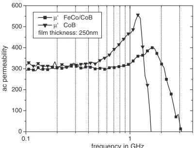
In previous investigations it was found that exchange coupled CoB/FeCo multilayers with individual layer thick-nesses in the range of 1–15 nm are a very attractive material system for tailoring of high frequency properties in a wide range.11,14) As an example, the increase of the cut-off frequency of such a multilayer in comparison to a CoB single layer having both the same permeability is shown in Fig. 3. It can be seen that at constant permeability, the ferromagnetic resonance frequency could be shifted from 1.5 GHz for the single layer to over 3 GHz for the multilayer. At the same time, the damping in the multilayered film increased slightly.
The change of the real part of ac permeability determined at 1 GHz as a function of the applied strain is shown in Fig. 4. Due to the positive magnetostriction in this material tensile strain results in a gradual rotation of the easy axis into the rf
0.1 1
0 100 200 300 400 500 600
µ' FeCo/CoB
µ' CoB film thickness: 250nm
ac permeability
frequency in GHz
Fig. 3 AC permeability of a 250 nm thick FeCo/CoB multilayer film in
comparison to a CoB single layer film. While the permeability remains, the ferromagnetic resonance frequency could be shifted from 1.5 GHz to about 3.1 GHz by layering CoB with FeCo.
-0.075 -0.050 -0.025 0.000 0.025 0.050 0.075
0 200 400 600 800 1000 1200
compressive tensile
µac
' @ 1 GHz
ε in %
Fig. 4 Dependence of the ac permeability of an FeCo/CoB multilayer on
[image:2.595.327.527.366.519.2] [image:2.595.326.527.599.757.2]field direction. For low strains this rotation leads to a certain permeability. A strain of approximately 0.04% results in a spin flip into the rf field direction and the permeability suddenly vanishes, as now the easy axis is parallel to the exciting rf-field.
The strain that determines the permeability maximum depends on material and design parameters, i.e. shape anisotropy and internal stresses. In response to a compressive strain the easy axis becomes more stable in the direction perpendicular to resulting in a gradual decrease of the permeability.
The upper frequency limit due to eddy current losses is given by:
fec¼
4
0rt2
where t is the layer thickness and the resistivity of the magnetic material. For typical values of the resistivity of amorphous magnetostrictive material this frequency limit is responsible for the cut-off frequency if the t1:5mm
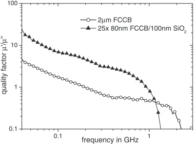
(¼300,¼100mcm). Therefore, an increase inQcan be obtained by lamination of the magnetostrictive material (e.g. CoB/FeCo multilayers) with additional insulating layers (e.g.SiO2) in a kind of transformer core design.15,16)
The benefit of this approach is demonstrated by a comparison of two 2mm CoB/FeCo multilayers, one as a solid metallic film without SiO2interlayers, the other divided
into 25 layers separated by 100 nm SiO2 layers (Fig. 5). For
frequencies higher than 50 MHz the SiO2layering results in a
significant increase of the real part of the permeability (0). At the same time the imaginary part (00) decreases up to 400 MHz leading to an important increase of the material quality factor Q¼0=00. This factor limits the overall quality factor that can be obtained when using magneto-strictive LC circuits.
The magnetostrictive multilayer thin films discussed above have been integrated as sensing elements in a LC circuit fabricted in thin film technique. These LC circuits consist of a strip inductor (Au, 100mm wide, 0.9–2.1 mm long) sur-rounded by magnetostrictive layers, which are isolated against the conductor by SiO2 layers. The values of the
inductance and the capacitance were adjusted to yield a LC
resonance frequency of approximately 500 MHz. The overall device quality factor at this frequency equaled approximately 9, about the same value as for the materialQ itself at this frequency. The magnetic easy axis was oriented parallel to the strip. For the present sensor the magnetostrictive layers consist of 25 CoB/FeCo multilayers of 80 nm thickness each laminated by 50 nm SiO2layers (Fig. 6).
Further reduction of eddy currents can be obtained by lateral patterning of the magnetostrictive material as shown in Fig. 7. Here, the magnetic material surrounding the inductor strip was segmented to eliminate current flow parallel to the strip.
Applying a tensile stress perpendicular to the strip inductor results in a gradual rotation of the magnetic domains into the stress direction. To measure this influence of strain on the LC circuits the devices were mounted into a 4-point bending test jig (Fig. 8). A pusher block controlled by a linear stepping motor, allowed a defined bending of the device. The sensor is remotely interrogated by an excitation and a pick-up coil mounted at a distance of approximately 2 mm. The resonance frequency is determined from the transmitted signal (S21)
[image:3.595.307.549.73.200.2]using a network analyzer (Rohde&Schwarz Vector Network Analyzer 20 kHz–8 GHz ZVCE).
Figure 9 shows the dependence of the resonance frequency of the LC circuit on the applied stress. Corresponding to the behavior of the permeability shown in Fig. 4, the perme-ability increased first, leading to an increase of the inductance and consequently a decrease of the resonance frequency. At a certain strain ("¼0:03%, uno external magnetic bias) the permeability suddenly drops to 1 resulting in a corresponding
0.1 1
0.1 1 10 100
2µm FCCB
25x 80nm FCCB/100nm SiO2
quality factor
µ
'/
µ
''
frequency in GHz
Fig. 5 Frequency dependence of the quality factor of a 2mmthick FeCo/
CoB multilayer and a (FeCo/CoB)/SiO2 laminated film with equal
magnetic volume.
Fig. 6 Scanning electron microscopy image of a cross section of the strip
inductor made by focused ion beam milling. The image shows the inner conductor, isolating and magnetic layers.
Fig. 7 Scanning electron microscopy image of the segmented strip
[image:3.595.306.550.268.380.2] [image:3.595.70.271.599.747.2]increase of resonance frequency.
By applying a magnetic bias field—or bias stress (not shown)—the characteristic of the resonance frequency on applied stress (Fig. 9) can be shifted resulting ine.g.a gradual increase of resonance frequency with the applied tensile strain (in case of a magnetic bias field of 20 G perpendicular to the initial easy axis).
A figure of merit (FoM) of the LC circuit given by the relative change in frequency (f=f0) over the change in strain
(") can be defined as
FoM¼f
f0
=":
Values exceeding 1000 have been obtained depending on the bias field and the range of strain. These values are extraordinarily high compared to the resistive type of strain gauges with an equivalent gauge factor
FoM¼R
R0
="
where R=R0 denotes the relative change in resistance.
Maximum gauge factors are 4 for metallic, 180 for piezoresistive and 600 for magnetostrictive TMR strain gauges.9)Another advantage of LC circuit strain gauges is that the measurement of frequencies instead of analogous signals is significantly less sensitive to disturbances.
[image:4.595.81.257.68.213.2]A possible application for this type of sensor is the measurement of torque. Figure 10 shows preliminary data for a magnetostrictive LC circuit attached to a non-magnetic steel shaft. The data were obtained using the inductive coupling method similar to the read-out scheme shown in Fig. 8.
4. Conclusions
A LC circuit type strain sensor featuring wireless inter-rogation has been developed and fabricated. The prototype sensor uses exchange coupled CoB/FeCo multilayers with additional isolating layers as sensing element. The devices are displaying quality factors of about 9 at resonance frequencies of approximately 500 MHz. In strain measure-ments a gauge factor of about 1000 could be measured. The feasibility of this sensor principle has been demonstrated for torque measurements.
Future work will concentrate on design optimization of the sensor element, further improvement of the magnetostrictive material and on the development of a suitable read-out electronic.
Acknowledgements
The authors acknowledge fruitful discussions with Alfred Ludwig, and Michael Tewes (caesar), and Manfred Wuttig (University of Maryland). The authors would like to thank Jeff McCord (IFW Dresden, Germany) for the domain observations.
REFERENCES
1) L. P. Shen, T. Uchiyama, K. Mohri, E. Kita and K. Bushida: IEEE
Trans. Magn.33(1997) 3355.
2) K. Mohri, T. Uchiyama, L. P. Shen, C. M. Cai and L. V. Pawin: Sensors
and Actuators A91(2001) 85.
3) C. H. Tyre´n, D. G. Lord, United States Patent No. 5297439 (1994).
Fig. 8 Sketch of the strain measurement set-up consisting of a block
pushing against a printed circuit bord. The LC circuit is placed on the 4-point bending jig and excited and read out by two small coils. A magnetic bias field can be applied in different directions by a pair of Helmholtz coils.
0.00 0.01 0.02 0.03 0.04 0.05 0.06 0.07 0.08 0.09 0.10 360
380 400 420 440 460
∆ε
∆f
f0
∆f/f0 /∆ε = 543
∆f/f 0 /∆ε = 991
∆f/f0 /∆ε = 1380
20.15G Hext perpend. to EA no Hext
19.91G Hext parallel to EA
circuit resonance frequency in MHz
ε in %
Fig. 9 Dependence of the resonance frequency of the LC circuit on applied
stress for different external magnetic fields. A figure of merit of about 1000 could be obtained with devices like this one.
-200 -150 -100 -50 0
490 500 510
and axis 0°
axis turned by 180°
resonance frequency in MHz
[image:4.595.329.527.72.214.2]torque in Nm
Fig. 10 Results of a torque measurement using stress sensitive LC circuits.
4) B. B. Pant and D. R. Krahn: J. Appl. Phys.69(1991) 5936–5938.
5) R. C. O’Handley and A. R. Childress: IEEE Trans. Magn.31(1995)
2450.
6) M. J. Mawin, G. A. Gurney, D. R. Wilhout and V. S. Speriosa: Appl.
Phys. Lett.72(1998) 3320.
7) L. Basil, B. Gurney, D. Wilhout and V. S. Speriosa: J. Appl. Phys.85
(1999) 3320.
8) T. Duenas, A. Sehrbrock, M. Lo¨hndorf, A. Ludwig, J. Wecker, P.
Gru¨nberg and E. Quandt: J. Magn. Magn. Mater.242–245(2002) 1132.
9) M. Lo¨hndorf, T. Duenas, M. Tewes, E. Quandt, M. Ru¨hrig and J.
Wecker: Appl. Phys. Lett.81(2002) 313.
10) E. Quandt and A.E. Clark: Proc. Actuator 98, 356–361.
11) A. Ludwig, M. Tewes, S. Glasmachers, M. Lo¨hndorf and E. Quandt: J.
Magn. Magn. Mater.242–245(2002) 1126.
12) R. D. Shull, E. Quandt, A. J. Shapiro and M. Wuttig: submitted to IEEE Trans. Magn.
13) J. McCord, R. Scha¨fer, M. Frommberger, S. Glasmachers and E. Quandt: submitted to the joint Intermag/MMM conference (2004). 14) A. Ludwig: Appl. Surf. Sci. (2003) in print.
15) M. Senda and O. Ishii: IEEE Trans. Magn.30(1994) 155.