Thermal Effect on Wave Interaction in Composite
Structures
R.K. Apalowo, D. Chronopoulos and V. Thierry
Abstract—There exist a wide range of failure modes in composite structures due to the increased usage of the struc-tures especially in aerospace industry. Moreover, temperature dependent wave response of composite and layered structures have been continuously studied, though still limited, in the last decade mainly due to the broad operating temperature range of aerospace structures. A wave finite element (WFE) and finite element (FE) based computational method is presented by which the temperature dependent wave dispersion characteristics and interaction phenomenon in composite structures can be predicted. Initially, the temperature dependent mechanical properties of the panel in the range of -100◦C to 150◦C are measured experimentally using the Thermal Mechanical Analysis (TMA). Temperature dependent wave dispersion characteristics of each waveguide of the structural system, which is discretized as a system of a number of waveguides coupled by a coupling element, is calculated using the WFE approach. The wave scattering properties, as a function of temperature, is determined by coupling the WFE wave characteristics models of the waveguides with the full FE modelling of the coupling element on which defect is included. Numerical case studies are exhibited for two waveguides coupled through a coupling element.
Index Terms—Temperature dependent mechanical characteris-tics, Wave propagation properties, Damage detection, Wave finite element, Composite structure.
I. INTRODUCTION
Composite structures are being increasingly used in many industrial fields, such as aerospace and military, due to their versatile physical and mechanical properties. However, an aerospace structure typically operates within a broad
tem-perature range, varying between 100◦C to 200◦C for launch
vehicles and 60◦C to +50◦C for aircrafts. Hence, an attempt is made in order to exhibit the sensitivity of the wave interaction properties of a composite structure to the ambient flight temperature.
Recently, the effect of high temperature on the thermome-chanical response of various composite structures, such as multi-layered plates and shells [1], glass epoxy composites [2], [3] and carbon fibre epoxy composites [4], [5], has been extensively assessed. However, investigation of the thermoa-coustic behaviour of composites has been found almost in-existent in the open literature. So, there is a great need for the investigation of temperature dependent dynamic behaviour of composite laminates. Of particular importance is investigating the interaction of wave propagation with damage with respect to temperature.
Wave propagation damage detection methods are based on calculating the reflection and transmission coefficients at the point of inhomogeneity. Of these, the Wave and Finite Element (WFE) method [6], [7], [8], [9] is one of the most efficient
computational methods suitable for predicting the vibrational response and wave interaction with damage in various types of structures. The method has recently found applications in predicting the vibroacoustic and dynamic performance of composite panels and shells [10], [11], [12], [13], [14], [15], [16] , with pressurized shells [17], [18] and complex periodic structures [19], [20], [21] having been investigated. The vari-ability of acoustic transmission through layered structures [22], [23], as well as wave steering effects in anisotropic composites [24] have been modelled through the same methodology. However, this numerical method has not been implemented to investigate the effect of temperature on wave scattering. Temperature dependent wave interaction properties would be useful for structural defect and evaluation within broad range of temperature.
In this work, the effect of temperature on the wave inter-action of composite laminates is considered. The temperature dependent mechanical properties of the laminate constituents materials are experimentally calculated using the Thermal Mechanical Analysis. A WFE approach is used to calculate the wave propagation properties, and then coupled to finite element modelling of the coupling joint in order to calculate wave interaction coefficients form the joint. The paper is organised as follows. Section II presents the experimental mea-surement of the temperature dependent mechanical properties of the composite facesheet and core materials. Section III presents the calculations waves propagation properties. Waves interaction modelling is presented in Section IV. Numerical examples are presented in Section V. Section VI presents concluding remarks of the work.
II. MEASUREMENT OF MECHANICAL CHARACTERISTICS
A Thermal Mechanical Analysis (TMA) device is used to measure the mechanical characteristics of a sandwich panel comprising of a carbon epoxy facesheet and a quasi-isotropic honeycomb core, which absorbs and adheres to the resin in which the facesheet is impregnated. In the polymerisation process, the resin serves as the facesheet matrix as well as the binding agent. The nominal mechanical characteristics of
the composite panel’s constituents at 20◦Care shown in Table
I. Measurements are made at a temperature range of -5◦C to
150◦C.
TABLE I
NOMINAL MECHANICAL PROPERTIES OF THE COMPOSITE LAMINATE’S
CONSTITUENTS AT20◦C
Carbon Epoxy Honeycomb foam
E= 54GPa Ex= 85MPa
ρ= 1410kg/m3
Ey= 85MPa
ν= 0.09 ρ= 48kg/m3
νxy= 0.23 Gyz= 44MPa Gxz= 44MPa
Fig. 1. Configuration of a segment of the facesheet traction test in the TMA device
Fig. 2. Configuration of a segment of the core shear deformation in the TMA device
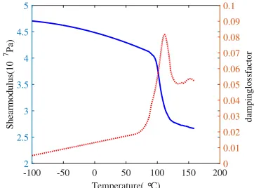
The measured elastic (Fig. 3) and shear (Fig. 2) moduli decrease slightly while their corresponding material loss ratios
increases slightly with respect to temperature until 110◦C,
where the glass transition occurs. Beyond this temperature, the moduli and the loss factor decrease rapidly, then the loss
factor (about 130◦C) start increasing again due to the high
viscosity of the resin.
III. WAVE PROPAGATION BY A WAVE AND FINITE ELEMENT
METHOD
Wave propagation along the x direction of an arbitrary
layered structural waveguide (Fig. 5) is modelled by a WFE method using the transfer matrix approach [25].
By the WFE method, a periodic segment (of length
equiva-lent to one element alongx) is modelled. The frequency and
temperature dependent dynamic stiffness matrix (DSM) of the segment is given as
Temperature (°C)
-100 -50 0 50 100 150 200
Elastic modulus (10
10Pa)
0 1 2 3 4 5 6
damping loss factor
[image:2.595.106.246.138.338.2]0 0.02 0.04 0.06 0.08 0.1 0.12 0.14 0.16 0.18 0.2
Fig. 3. Experimentally measured temperature dependent elastic modulus (-) and material loss factor (· · ·) for the facesheet material
Temperature (°C)
-100 -50 0 50 100 150 200
Shear modulus (10
7Pa)
2 2.5 3 3.5 4 4.5 5
damping loss factor
0 0.01 0.02 0.03 0.04 0.05 0.06 0.07 0.08 0.09 0.1
Fig. 4. Experimentally measured temperature dependent shear modulus (-) and material loss factor (· · ·) for the honeycomb core material
ࢾ
LJ
dž nj
Fig. 5. WFE modelled waveguide with left and right side nodes bullet marked. Range of interior nodes also illustrated
D(ω, T) =K(ω, T)−ω2M(ω) +iωC(ω, T) (1)
where K, M andC are the temperature dependent stiffness,
[image:2.595.347.528.290.424.2] [image:2.595.121.229.376.516.2] [image:2.595.347.523.474.613.2]
DLL DLI DLR
DIL DII DIR
DRL DRI DRR
qL qI qR = fL 0 fR (2)
withqandfthe displacement and forcing vectors respectively.
Using a Guyan-type condensation for the internal DoFs, the problem can be expressed as
D∗
LL D∗LR
D∗
RL D∗RR
qL qR = fL fR (3)
Assuming no external forces are applied, the displacement continuity and force equilibrium at the interface of two
con-secutive periodic segments randr+ 1are given as
qR(r)=qL(r+1); fR(r)=−fL(r+1) (4)
combining Eqs. (3) and (4) gives
q
L(r+1)
fL(r+1)
=T
q
L(r)
fL(r)
(5)
where matrixTis the symplectic transfer matrix expressed as
T=
−D∗LR−
1D∗
LL D∗LR−
1
−D∗RL+D∗RRD∗LR−
1D∗
LL −D∗RRD∗LR− 1
(6)
The propagation constantλ= exp−ikδx
of the wave relates the right and left nodal displacements and forces as
λqL(r)=qR(r); −λfL(r)=FR(r) (7)
and substituting Eqs. (4) and (7) into Eq. (5) gives the eigenproblem
whose eigenvalues and eigenvectors solution sets provide a comprehensive description of propagation constants and wave modes of waves along the waveguide at specified frequency and temperature.
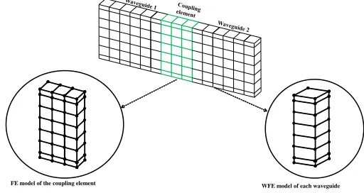
IV. WAVE INTERACTION BY A HYBRIDWFE/FEMETHOD
Consider two waveguides connected through a coupling joint (Fig. 5). The joint is fully FE modelled and can contain damage, geometric or material inconsistencies.
The wavemodes, obtained at each frequency and tempera-ture, for each waveguide in the system can be grouped as
Φ=
Φqinc Φqref
Φfinc Φfref
(8)
where inc and ref denote the positive and negative going
waves respectively. The modes of the two waveguides in the system can be grouped as
Ψqinc=
Φq1inc 0
0 Φq2inc
(9)
with similar expressions for Ψqref, Ψfinc and Ψfref.
As-suming modal decomposition, the physical domain can be converted to the wave domain as
[image:3.595.308.564.105.241.2]FE model of the coupling element WFE model of each waveguide
Fig. 6. Caption of a system as two collinear waveguides connected through a coupling joint
qL fL =Φ Qinc Qref (10)
whereQdenotes the amplitudes of the wave modes.
The DSM of the joint can be partitioned with regard to the interface and non-interface nodes with the waveguides as
D11 D12
D21 D22
q1 q2 = f1 f2 (11)
where subscript1corresponds to the interface DoFs and2the
non-interface DofFs. Condensing the non-interface DoFs, the DSM can be expressed as
D∗
C=D11−D12D−221D21 (12)
Applying displacement continuity and equilibrium of forces
at the connecting interfaces, the scattering matrix S of the
joint, whose partitions relate the amplitudes of the incident and scattered waves as
Q1ref
Q2ref
=S
Q1inc
Q2inc
(13)
where
S=−[Ψfref−D∗CΨqref]−1[Ψfinc−D∗CΨqinc] (14)
with diagonal elements being the reflection coefficients and off the diagonal the transmission coefficients of the scattered waves.
V. NUMERICALRESULTS
The methodology presented in this work is demonstrated on two numerical case examples: two collinear rods connected through a finite joint, and two sandwich laminates connected through a laminate joint. Calculations are made at five different
temperatures, -100, 25, 90, 110 and 150◦Cfor the composite
laminate example and at three different temperatures, 25, 90
ݔ ܽ
ଵା ܽଶା
[image:4.595.350.529.96.408.2]ܽଵି
Fig. 7. Two rods coupled through a finite rod joint
Frequency [105Hz]
0 0.5 1 1.5 2 2.5 3 3.5 4
Wavenumber [1/m]
0 200 400 600 800 1000 1200
Analytical, 250C WFE, 250C
Analytical, 900C WFE, 900C Analytical, 1500C WFE, 1500C
Fig. 8. Predicted temperature dependent dispersion curves for the rod
A. Two Collinear rods coupled through a finite rod
Consider two similar and collinear long rods undergoing longitudinal vibration. A finite rod of a different material properties is sandwiched between them as shown in Fig. (7).
Cross-sectional areas A1 = A2 = AJ = 0.003m2, lengths
L1 =L2 = 0.2m and L= 0.003m. Both rods are made of
carbon epoxy while the coupling joint is made of honeycomb foam (Table I).
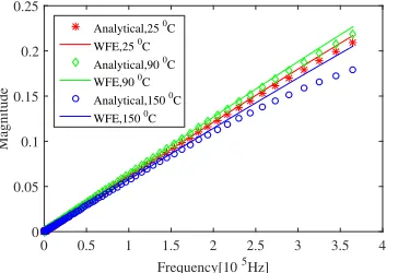
The results of the analytically [26] and numerically obtained wave dispersion relation and interaction coefficients for the problem are presented in Figs. (8) and (9)
Excellent agreement is observed between the analytically and numerically obtained results with little deviation at high frequency due to FE discetisation errors. The results also show a linear proportional increase in the interaction coefficient with respect to temperature. The proportional increment is observed
until the glass transition temperature (110◦C), beyond this
temperature, the coefficient value decreases proportionally.
Frequency [105Hz]
0 0.5 1 1.5 2 2.5 3 3.5 4
Magnitude
0 0.05 0.1 0.15 0.2 0.25
Analytical, 250C
WFE, 250C Analytical, 900C
WFE, 900C
Analytical, 1500C WFE, 1500C
Fig. 9. Predicted temperature dependent reflection coefficients for a finite joint connecting two rods
Frequency [104Hz]
0 2 4 6 8 10
Wavenumber [1/m]
10-2 100 102
(a) 25◦C
Frequency [104Hz]
0 2 4 6 8 10
Wavenumber [1/m]
10-2 100 102
[image:4.595.83.267.100.147.2](b) 150◦C
Fig. 10. Dispersion relations for waves in the composite laminate at 25◦C and 150◦C
B. Composite laminate
Two collinear composite laminates connected by through a coupling joint(another composite panel on which damage
is modelled) of the same cross-section (5mm × 10mm).
A periodic segment of the quasi-isotropic sandwich panel comprises of a honeycomb foam core sandwiched between two carbon fibre facesheets. The temperature dependent mechani-cal properties (elastic and shear moduli) and their respective material loss factor of the materials are presented in Figs. 3
and 4. The thickness of the core, hc, is 10 mm while that of
the facesheet, hc, is 1 mm. The length of the coupling joint
is 3mm while that of each waveguide is arbitrary, as only a
periodic segment (as shown in Fig. 6) is needed for the WFE model.
Surface breaking crack of 1mm width and 2mm depth
located at 1mm along the length of the coupling joint. The
crack is modelled through the node duplication approach [27]. Temperature dependent dispersion curves for the propagat-ing waves within the system are shown in Figs. 10 and 11.
Four propagating waves, in-plane and out-of-plane flexural waves as well as torsional and axial waves, exist below the frequency of 10 kHz. The cut-on frequencies and number of waves within the considered frequency range depend on temperature as shown in Fig. 10.
While at 25◦C, there are nine waves within the the
[image:4.595.87.266.191.316.2] [image:4.595.88.270.612.737.2]Frequency [104Hz]
0 2 4 6 8 10 12
Wavenumber [1/m]
[image:5.595.351.526.99.250.2]0 200 400 600 800 1000 1200 1400
Fig. 11. Dispersion relations for torsional waves in the composite laminate at -100◦C(o), 25◦C(+), 90◦C(*), 110◦C(x) and 150◦C(
· · ·)
Frequency [104Hz]
0 2 4 6 8 10 12
Magnitude
0 0.1 0.2 0.3 0.4 0.5
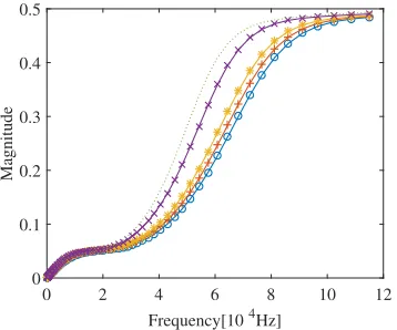
Fig. 12. The temperature dependent reflection coefficient magnitude of the flexural wave from cracked joint of the composite laminate at -100◦C (o), 25◦C(+), 90◦C(*), 110◦C(x) and 150◦C(
· · ·)
25kHz, 75kHz and 90kHz as shown in Fig. 10a, there are
eleven waves at 150◦C, with cut-ons occurring at about
10kHz, 12kHz, 22kHz, 68kHz, 78kHz, 102kHz and 109kHz as shown in Fig. 10b. The effect of temperature on the wavenumber magnitude can be analysed using the temperature dependent torsional wave dispersion relation shown in Fig. 11. There is a difference of about 30% between the wavenumbers at -100◦C, 25◦C and 90◦C, and at 150◦C. The variation in the waves properties as a function of temperature can be said to be as a result of the variation in the material properties and material loss factor at different temperature.
Results of the reflection coefficients magnitude of the prop-agating waves are presented in Figs. (12), (13) and (14).
Scattering coefficient trends of the axial and torsional waves show more sensitivity to change in temperature at higher frequencies in the range above 60kHz, while that of the flexural wave shows significant difference only in the range 25kHz to 85kHz but insignificant to temperature change outside this frequency range. The overall difference of the scattering coefficients in these two temperature ranges (before and after glass transition) for all the waves is about 50%. However, the effect of temperature on the reflection
coeffi-Frequency [104Hz]
0 2 4 6 8 10 12
Magnitude
0 0.1 0.2 0.3 0.4 0.5 0.6 0.7
Fig. 13. The temperature dependent reflection coefficient magnitude of the torsional wave from cracked joint of the composite laminate at -100◦C (o), 25◦C(+), 90◦C(*), 110◦C (x) and 150◦C(
· · ·)
Frequency [104Hz]
0 2 4 6 8 10 12
Magnitude
0 0.05 0.1 0.15 0.2 0.25
Fig. 14. The temperature dependent reflection coefficient magnitude of the axial wave from cracked joint of the composite laminate at -100◦C(o), 25◦C (+), 90◦C(*), 110◦C(x) and 150◦C(
· · ·)
cient below, within and after the glass transition temperature varies significantly. Below the glass transition temperature, there exist slight increase in the reflection coefficients of all the wave types with a maximum difference of about 10%
per 50◦C change in temperature. Above the glass transition
temperature, a considerable difference is observed with respect to temperature change with an observed difference of about
28% per 50◦C change in temperature.
VI. CONCLUDING REMARKS
[image:5.595.86.263.100.248.2] [image:5.595.87.266.294.443.2] [image:5.595.351.526.302.449.2]The panel is then idealised as a system of two waveguide segments connected through a coupling joint. The wave finite element modelling of each waveguide segment is then coupled with the full finite element of the coupling joint, on which damage is modelled, in order to calculate the scattering coefficients of the waves interaction with the damage. As in the case of the experimental results for the moduli and the material loss factor, the numerical predicted wave propagation properties and the wave scattering coefficients exhibit notable differences in their results before the glass transition tempera-ture compared to after the glass transition temperatempera-ture. It can be concluded that temperature is a significant factor that should be taken into consideration in the design process of aerospace material in order to improve its wave response performance.
REFERENCES
[1] A. Noor and U. Burton, “Computational models for high temperature multilayered composite plates and shells,” Appl Mech Rev, vol. 45, no. 10, pp. 419–446, 1992.
[2] Y. Dimitrienko, “Thermomechanical behaviour of composite materials and structures under high temperature: 1. materials, composites,”Part A. Applied Science and Manufacturing, vol. 28, pp. 463–471, 1997. [3] ——, “Thermomechanical behaviour of composite materials and
struc-tures under high temperature: 2. strucstruc-tures, composites,”Part A. Applied Science and Manufacturing, vol. 28, pp. 453–461, 1997.
[4] G. McNally, M. McCourt, and P. Spedding, “The effect of rapid high temperature excursions on the moisture absorption and dynamic mechan-ical properties of carbon fibre epoxy composite materials, development in chemical engineering and mineral processing,”Asia-Pacific Journal of Chemical Engineering, vol. 12, no. 1, pp. 169–178, 2004.
[5] O. Putkis, D. R. P., and C. A. J., “The influence of temperature variations on ultrasonic guided waves in anisotropic cfrp plates,” Ultrasonic, vol. 60, pp. 109–116, 2015.
[6] W. J. Zhou and M. N. Ichchou, “Wave scattering by local defect in structural waveguide through wave finite element method,” Structural Health Monitoring, vol. 10, no. 4, pp. 335–349, 2011.
[7] J. Renno and B. Mace, “Calculation of reflection and transmission coefficients of joints using a hybrid element/wave and finite element approach,”Journal of Sound and Vibration, vol. 332, pp. 2149–2164, 2013.
[8] ——, “Vibration modelling of structural networks using a hybrid finite element/wave and finite element approach,”Wave Motion, vol. 51, no. 4, pp. 566–580, 2014.
[9] E. Manconi and B. Mace, “Modelling wave propagation in two-dimensional structures using finite element analysis,” ISVR Technical Memorandum, vol. 318, no. 4–5, pp. 884–902, 2008.
[10] D. Chronopoulos, B. Troclet, M. Ichchou, and J. Laine, “A unified approach for the broadband vibroacoustic response of composite shells,”
Composites Part B: Engineering, vol. 43, no. 4, pp. 1837–1846, 2012. [11] D. Chronopoulos, B. Troclet, O. Bareille, and M. Ichchou, “Modeling the response of composite panels by a dynamic stiffness approach,”
Composite Structures, vol. 96, pp. 111–120, 2013.
[12] D. Chronopoulos, M. Ichchou, B. Troclet, and O. Bareille, “Efficient prediction of the response of layered shells by a dynamic stiffness approach,”Composite Structures, vol. 97, pp. 401–404, 2013. [13] ——, “Predicting the broadband vibroacoustic response of systems
subject to aeroacoustic loads by a krylov subspace reduction,”Applied Acoustics, vol. 74, no. 12, pp. 1394–1405, 2013.
[14] ——, “Thermal effects on the sound transmission through aerospace composite structures,”Aerospace Science and Technology, vol. 30, no. 1, pp. 192–199, 2013.
[15] ——, “Predicting the broadband response of a layered cone-cylinder-cone shell,”Composite Structures, vol. 107, no. 1, pp. 149–159, 2014. [16] ——, “Computing the broadband vibroacoustic response of arbitrarily thick layered panels by a wave finite element approach,” Applied Acoustics, vol. 77, pp. 89–98, 2014.
[17] V. Polenta, S. Garvey, D. Chronopoulos, A. Long, and H. Morvan, “Optimal internal pressurisation of cylindrical shells for maximising their critical bending load,”Thin-Walled Structures, vol. 87, pp. 133– 138, 2015.
[18] T. Ampatzidis and D. Chronopoulos, “Acoustic transmission properties of pressurised and pre-stressed composite structures,”Composite Struc-tures, vol. 152, pp. 900–912, 2016.
[19] I. Antoniadis, D. Chronopoulos, V. Spitas, and D. Koulocheris, “Hyper-damping properties of a stiff and stable linear oscillator with a negative stiffness element,”Journal of Sound and Vibration, vol. 346, no. 1, pp. 37–52, 2015.
[20] D. Chronopoulos, M. Collet, and M. Ichchou, “Damping enhancement of composite panels by inclusion of shunted piezoelectric patches: A wave-based modelling approach,”Materials, vol. 8, no. 2, pp. 815–828, 2015.
[21] D. Chronopoulos, I. Antoniadis, M. Collet, and M. Ichchou, “Enhance-ment of wave damping within metamaterials having embedded negative stiffness inclusions,”Wave Motion, vol. 58, pp. 165–179, 2015. [22] D. Chronopoulos, “Design optimization of composite structures
oper-ating in acoustic environments,” Journal of Sound and Vibration, vol. 355, pp. 322–344, 2015.
[23] M. Ben Souf, D. Chronopoulos, M. Ichchou, O. Bareille, and M. Haddar, “On the variability of the sound transmission loss of composite panels through a parametric probabilistic approach,”Journal of Computational Acoustics, vol. 24, no. 1, 2016.
[24] D. Chronopoulos, “Wave steering effects in anisotropic composite structures: Direct calculation of the energy skew angle through a finite element scheme,”Ultrasonics, vol. 73, pp. 43–48, 2017.
[25] B. R. Mace, D. Duhamel, M. J. Brennan, and L. Hinke, “Finite element prediction of wave motion in structural waveguides,”The Journal of the Acoustical Society of America, vol. 117, no. 5, pp. 2835–2843, 2005. [26] J. Doyle,Wave Propagation in Structures: Spectral Analysis Using Fast
Discrete Fourier Transforms. Springer, 1997.