Distributed Speed Control for
Multi-Three Phase Electrical Motors
with Improved Power Sharing Capability
A. Galassini, A. Costabeber, C. Gerada
Power Electronic Machine Control Group (PEMC)The University of Nottingham, UK
A. Tessarolo
Engineering and Architecture Department The University of Trieste, IT
Abstract—This paper proposes a distributed speed control with improved power sharing capability for multi-three phase synchronous machines. This control technique allows the speed to be precisely regulated during power sharing transients among different drives. The proposed regulator is able to control the time constant of the current within thedq0reference frame to a step input variation. If compared to current set-point step variations, the proposed droop controller minimises device’s stress, torque ripple, and thus mechanical vibrations. Furthermore, since distributed, it shows improved fault tolerance and reliability. The design procedure and the power sharing dynamic have been presented and analysed by means of Matlab/Simulink and validated in a 22kW experimental rig, showing good agreement with the expected performances.
I. INTRODUCTION
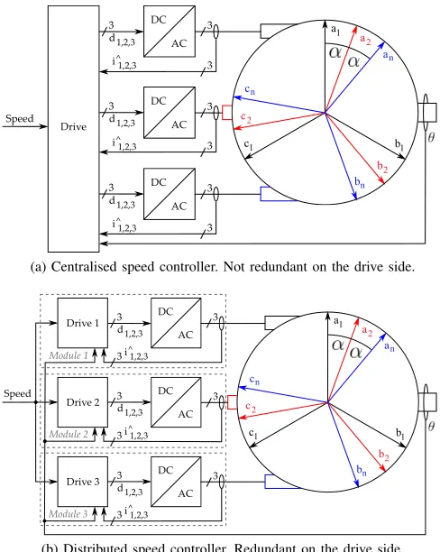
Multi-three phase electrical motors are gaining popularity thanks to the growing interest in the electrification of trans-portation systems [1]. Due to their advantages if compared against standard three-phase systems [2], multi-three phase electrical motors and multi-drive applications are still widely investigated, i.e. aerospace [3], [4], mining machines [5], [6], ships [7], [8], and road vehicles [9]. One of their main benefit is redundancy, leading to increased fault tolerance and reliability. On the other hand, system design and control complexity increase both on machine and on power conversion side, thus requiring higher development efforts. Furthermore, in order to guarantee constant operating power in case of partial failure, both machine segments and converters must be over-rated decreasing specific power (i.e. power-to-weight ratio) and power density (i.e. power per unit of volume). Among all the possible applications, multi-three phase motors have been widely developed in Integrated Modular Motor Drive (IMMD) scenario [10], [11]. In-fact, thanks to their intrinsic redundancy, they allow more reliable motor drive systems to be developed. Looking at Fig.s 1, full redundancy can be achieved only by the distributed speed configuration in Fig. 1b. Clearly, in case of drive fault in Fig. 1a, the system would be compromised. On the other hand, in the centralised speed configuration where all the currents are fed back to the drive, all the sub-spaces can be controlled applying the Vector Space Decomposition (VSD) [12], and for this reason it allows better current control to be achieved [13].
(a) Centralised speed controller. Not redundant on the drive side.
[image:1.612.314.558.215.521.2](b) Distributed speed controller. Redundant on the drive side.
Fig. 1. dk stands for duty cycle,ikfor current (k= 1,2,3).aj,bj,cj are the phases of the j-th set of windings (j= 1..n).θis the rotor position.
ω
−
P ID
eω ySP ωD
KiShj 1s
ω
−
KDj
−
i∗
P II
ei v 1
sdx+rs
ev
Kt
Kb
−
i
−
ω
−
P ID
eω ySP ωD
KiShj
1
s
ω
−
KDj
−
i∗
P II
ei v 1
sdx+rs
ev
Kt
Kb
−
i
−
ω∗
+
+
1
sJ+B TL
− ω
GEQj = KiShj s+KiShjKDj
GEQj = KiShj s+KiShjKDj
GI= s+ωcωc
GI= s+ωcωc
[image:2.612.60.559.50.202.2]Mechanical part
Fig. 2. q-axes of the proposed distributed speed control schematic within the synchronous reference frame without axes decoupling.
speeds control loop design is detailed and the Common Speed Reference (CSR) and Torque Follower (TF) configurations are explained [18]. Whilst Section IV introduces power sharing feature based on droop control strategy, Section V details the compensation loop needed to restore the steady state speed drop. In order to clarify the experimental validation shown in Section VII, Section VI summarises the whole control procedure. Conclusions are finally given in Section VIII.
II. CURRENT CONTROL
The current control loops design has been based on the first harmonic inductance obtained from the Vector Space Decomposition (VSD) [12]. Considering switching delays (Tsw) and current filter cut-off frequency (ωf c), d-q current
P I controller proportional (KpI) and the integral (KiI) gains have been designed on the following plant:
GIx(s) = 1
sTsw+ 1 1
sdx+rs
ω2 f c
s2+√2ω
f cs+ω2f c
(1)
where s is the Laplacian operator, x is d or q axis, rs is the phase stator resistance, and dx is the first d-q harmonic inductance calculated using the VSD [17].
III. SPEED CONTROL
Speed control is achieved either configuring all the drives in speed mode (Common Speed Reference - CSR) or configuring one drive in speed mode and the others in torque mode (Torque Follower - TF). The latter configuration is based on a master/slave approach, hence in case of master drive fault, the system is compromised. On the other hand, the CSR is distributed, guaranteeing system operation in case of fault of any of the drives. From now on, speed control will refer to the CSR configuration. Taking into account the current control loop cut-off frequency (ωc), speedP I controller proportional (KpS) and integral (KiS) gains have been computed on plant
GS in (2), whereJ is the inertia,B is the friction, andKtis the machine constant relating torque and iq current.
GS(s) =
ωc
s+ωc
Kt
sJ+B (2)
IV. POWER SHARING
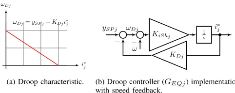
Power sharing in speed controlled multi-three phase motors can be achieved with tunable current set-points [18]. Current set-point step change would lead to discontinuity, hence cur-rent distortion and mechanical vibration. The proposed self-balancing sharing controller guarantees smooth transients even with step variations in sharing ratios. The regulator has been derived by the so called droop control strategy - common in power transmission systems - where the basic droop charac-teristic is a linear function with a negative coefficient on the Frequency/Active-Power plane [19].
i∗ j ωDj
ωDj=ySP j−KDji∗j
(a) Droop characteristic.
ySP j ωDj
KiShj 1s
ω
−
KDj −
i∗
j
(b) Droop controller (GEQj) implementation with speed feedback.
Fig. 3. jdenotes thej-thset of windings.KiShjis the integral sharing gain.
GEQj=
KiShj
s+KiShjKDj
(3)
Translating the droop concept from power systems to multi-three phase drives, the droop concept is a linear function with a negative coefficient (KDj) on the Speed/Current set-point plane (Fig. 3a). In Fig. 3b, the droop controller with the droop coefficientKDj is shown.ySP j andωDjare the speed and the internal (or drooped) speed set-point, respectively. The droop controller transfer function is in (3).
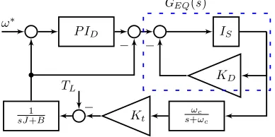
For simplicity, a distributed control schematic with just two sets of windings is shown in Fig 2.TL is the load torque,Kb is the electro-magnetic force constant, andP II is the current
[image:2.612.317.558.393.489.2]next sub-sections, design procedures for the droop regulator and theP IDcontroller for a given power sharing time constant and a given speed dynamics are detailed.
A. Equivalent model
Current P II controllers are tuned on stator resistance and first harmonic inductance values in equation (1). Droop controller parameters design must be carried out considering the whole amount of power produced by all the converters. Assuming balanced condition where all the converters are producing the same torque - denoted with (ES) -, the control schematic in Fig. 2 can be simplified with the equivalent collective control scheme in Fig. 4 where paralleled
cur-1
sJ+B ω∗
P ID IS
KD
−
Kt s+ωcωc
TL
− −
GEQ(s)
Fig. 4. Equivalent collective control scheme valid when the load power is equally split among thenmodules.Is=KiS/s.
rent loops (dashed red squares) have been replaced by the
GI =ωc/((s+ωc))transfer function. The parallel of droop controllers have been replaced by theGEQ=nG(ES)EQj transfer function valid if and only if [15]:
KiSh=KiShj(ES)n; KD=
KDj(ES)
n (4)
TheKDandKiSh parameters can be defined as the collective droop and collective integral gain coefficient respectively. Setting different values ofKDj andKiShj, it is possible to set the amount of torque produced by each drive and the power sharing time constant during current transients. Once droop controllers are tuned, outer compensation loop can be designed on the final speed dynamics specifications.
B. Current sharing dynamics
The total power is given by the sum of all the nominal torques produced by each module multiplied by the shaft speed. Since currents and torques are directly proportional (T =Kti), thej-thpower inp.u.isPj=Inom,j/(Pnj Inom,j) where Inom,j is the nominal current on the q-axis of the j-th module. From Fig. 2, it can be noticed that the current set-points are the output of the sharing regulators GEQj. Provided that in steady state the magnitude of the droop controllers in Eq. (3) is the reciprocal of the droop coefficient (|GEQj|s→0= 1/KDj), the power produced by each module can be re-written like the following:
Pj=
1/KDj n X
j
(1/KDj)
= 1/KDj
ε [p.u.] (5)
i
∗jω
DjK
D(ES1 )=
K
D(ES2 )K
D2&
P
1%=
P
2%P
2%%
[image:3.612.344.524.69.193.2]K
D1%
P
1%&
Fig. 5. Power sharing is achieved with different droop coefficients.
Thanks to Eq. 5, as long asεis kept constant, unbalanced power sharing can be achieved just changing the droop coeffi-cients as shown in Fig. 5. However, constant speed of the shaft is guaranteed if and only if the collective sharing regulator transfer function is kept constant: PnjGEQj = nG(ES)EQj =
GEQ. Therefore, constant speed operation is achieved updat-ing both the droop and the integral gain coefficient. Provided that PnjPj = 1, GEQ is kept constant by dividing the individual equal power droop coefficients KDj(ES) by a factor
ξj=nPj and multiplying the individual integral gainKiShj(ES) by the same factor ξj. Since the current sharing dynamics is governed by the droop controller GEQj, its closed loop time constant in Eq. (6) dominates the power sharing transient. Looking at Eq. (6), it is clear that constant sharing transient is obtained only updating both the coefficients.
τsharing,j = 1
KDjKiShj
(6)
V. COMPENSATION LOOP
Aim of the compensation loop is to restore the speed drop introduced by the droop controllers and to guarantee ade-quate speed dynamics performance. Looking at the equivalent collective scheme in Fig. 4, the plant GD for designing the compensationP I is described by Eq. (7).
GD(s) =
KiSh s+KiShKD
ωc s+ωc
Kt
sJ+B
1 +s+KiShKDKiSh s+ωcωc sJ+BKt (7)
VI. CONTROL DESIGN APPROACH
Based on the previous discussion, a possible design pro-cedure for each module with power sharing capability is summarised here. The system has been designed considering a speed set-pointω∗ = 30rad/s. Referring to the equivalent col-lective scheme,dandqcurrent controllers have been assigned the same bandwidth BWC = 211rad/s and the same phase margin P MC = 65◦ whereas the speed and compensation regulator has been designed with a BWD = 6rad/s and a
[image:3.612.80.274.220.317.2]TABLE I
DROOP CONTROLLER PARAMETERS
τsharing= 0.001[s] τsharing= 0.030[s]
j Pj Current KDj KiShj j Pj Current KDj KiShj
1,2,3(ES) 1/3(ES) 2 1.5(ES) 666.6(ES) 1,2,3(ES) 1/3(ES) 2 1.5(ES) 22.2(ES)
1 2/3 4 0.75 1333.3 1 2/3 4 0.75 44.4
2 1/12 0.5 6 166.6 2 1/12 0.5 6 5.5
3 1/4 1.5 2 500 3 1/4 1.5 2 16.6
how the proposed strategy is able to control current shar-ing dynamics. Lookshar-ing at the droop plane in Fig. 3a, the collective droop gain coefficient can be obtained imposing the maximum speed drop with the following Eq.: KD =
∆ωmax/(PnjInom,j). The maximum speed drop would be
the steady state output speed of the system without the P ID in nominal condition. In this particular case, the maximum delta has been set up equal to the 10% of the reference speed (∆ωmax = 3[rad/s]). Considering a total nominal current of 6[A], the collective droop coefficient KD(ES) =
∆ωmax/(PnjInom,j) = 0.5[(rad/s)/A] has been computed.
Therefore, KDj(ES) =nKD(ES) = 1.5[(rad/s)/A]. Looking at Table I, the integral gain KiShj(ES)= 1/(KDj(ES)τsharing,j) has been computed for 1[ms] and 30[ms], respectively. Finally, dividing the droop gain and multiplying the integral gain by the same factor ξj = nPj (for Pj = 2/3,1/12,1/4) power unbalancing has been obtained.
VII. EXPERIMENTAL VALIDATION
The proposed droop controller has been validated on a multi-three phase salient pole synchronous generator with one pole pair and nine phases shown in Fig. 7. Machine parameters are as follows: rs = 9.1Ω, dd = 0.045H, dq = 0.114H,
Kt = 3.06N m/A, J = 0.38N ms2, B = 0.14N ms. The motor has been connected to three off-the-shelf two-level three-phase converters (IRMD22381Q demo board combined to the FP25R12KE3 power modules from Infineon) controlled by an in-house developed control platform called uCube[20]. In order to connect the converters to theuCube, three interface
Fig. 7. Multi-three phase trig with motor, brake,uCube, rectifier, three two-level converters, nine current sensors, DC-link, bleeding resistors, and brake enable board.
0 0.02 0.04 0.06 0.08 0.1 Time [s]
0 0.5 1 1.5 2 2.5
Current [A]
Set-point i
d1 i
d2 i
d3 Simulation
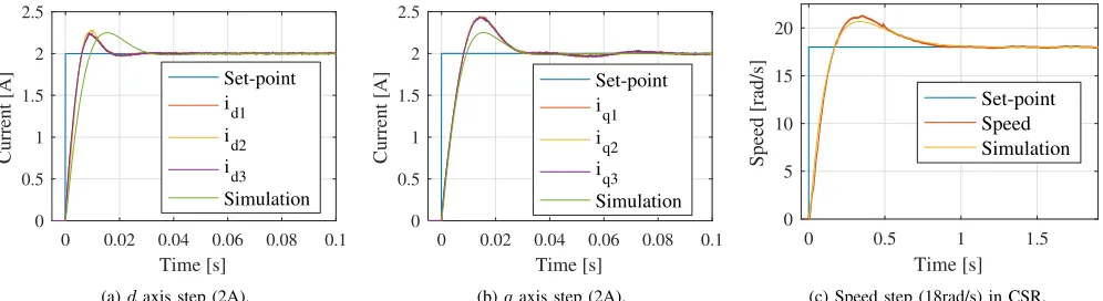
(a)daxis step (2A).
0 0.02 0.04 0.06 0.08 0.1 Time [s]
0 0.5 1 1.5 2 2.5
Current [A]
Set-point i
q1 i
q2 i
q3 Simulation
(b)qaxis step (2A).
0 0.5 1 1.5
Time [s]
0 5 10 15 20
Speed [rad/s]
Set-point Speed Simulation
[image:4.612.57.555.564.700.2](c) Speed step (18rad/s) in CSR.
9 10 11 12 Time [s]
24 26 28 30
Speed [rad/s]
Set-point Speed Simulation
(a) Speed variation with load step in CSR.
0 0.2 0.4 0.6 0.8 1
Time [s]
0 5 10 15 20 25
Speed [rad/s]
Set-point Speed Simulation
[image:5.612.58.554.62.202.2](b) Speed step (18rad/s) withoutP ID. (c) At full load withoutP ID∆ωmax= 3rad/s. Fig. 8. Speed dynamics in Common Speed Reference configuration and speed dynamics as in Fig. 2 but without compensationP ID.
cards with fibre optic receivers have been designed. The switching frequency and the sampling period have been set to 10kHz, whilst the DC link voltage was set to350V. Current have been measured by nine LEM LA-25P current sensors. In order to produce a load torque, the generator has been coupled to a hysteresis brake enabled by the control platform.
A. Current loop
Current step responses on d and q axes in locked rotor condition are shown in Fig.s 6a, 6b.
B. Speed Loop in Common Speed Reference configuration and without compensation loop
Speed step response and speed variation with load step from zero to full load TL = 55.2N m with all the drives in speed mode (CSR) are shown in Fig. 6c, 8a, respectively. Fig. 8b and 8c show the speed step response and the speed variation with load step without compensation loop. In this particular case the sharing time constant has been set to 30ms. In Fig. 8c, it is possible to appreciate how the speed drop increases withTL.
C. Compensation loop
In Fig.s 9a, 9b speed step response and speed variation with load step from zero to full load with system configured like in Fig. 2 are shown.
[image:5.612.324.549.269.454.2]D. Power sharing
Fig. 10. Power sharing.
Looking at Fig. 10, theiqcurrents under ramped input from zero to nominal speed are shown. After 10s the brake have been enabled. The system was in (ES) condition until second 17.5. At that point, the droop and the integral coefficients
0 0.5 1 1.5 2
Time [s]
0 5 10 15 20 25
Speed [rad/s]
Set-point Speed Simulation
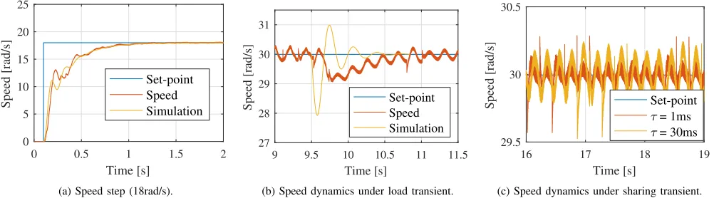
(a) Speed step (18rad/s).
9 9.5 10 10.5 11 11.5 Time [s]
27 28 29 30 31
Speed [rad/s] Set-point Speed Simulation
(b) Speed dynamics under load transient.
16 17 18 19
Time [s]
29.5 30 30.5
Speed [rad/s] Set-point
= 1ms = 30ms
(c) Speed dynamics under sharing transient.
[image:5.612.55.556.564.703.2]have been programmed for unbalanced sharing like reported in Table I in the previous Section.
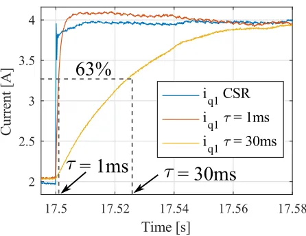
Fig. 11. Sharing time constants comparison.
In Fig. 11, the difference between the current set-point step change - with the system configured in CSR - and the droop controller is highlighted. Whilst current set-point step change leads to current distortion and could potentially excite mechanical resonances, droop controlled transients smoothly reach the steady state with predicted time constants reported in Table I. In Fig. 9c, unaffected speed dynamics under power sharing transient for different time constants is shown.
VIII. CONCLUSIONS
This paper focused on power sharing in multi-three phase speed controlled electrical systems. The so called Speed-Drooped control has been validated on a multi-three phase rig with a salient pole synchronous generator with nine phases. If compared to current steps in Common Speed Reference (CSR) configuration, droop control allows the torque transients to be controlled guaranteeing constant shaft speed. Thanks to the Vector Space Decomposition (VSD), mutual interactions among different sets of windings have been taken into account in the control design. Despite the presence of the electro-magnetic couplings within the machine, the droop controller has been successfully validated controlling power sharing transients as predicted.
REFERENCES
[1] R. Bojoi, S. Rubino, A. Tenconi, and S. Vaschetto, “Multiphase electrical machines and drives: A viable solution for energy generation and transportation electrification,” in 2016 International Conference and Exposition on Electrical and Power Engineering (EPE), Oct 2016, pp. 632–639.
[2] E. Levi, “Advances in converter control and innovative exploitation of additional degrees of freedom for multiphase machines,” IEEE Transactions on Industrial Electronics, vol. 63, no. 1, pp. 433–448, Jan 2016.
[3] B. Sarlioglu and C. T. Morris, “More electric aircraft: Review, chal-lenges, and opportunities for commercial transport aircraft,”IEEE Trans-actions on Transportation Electrification, vol. 1, no. 1, pp. 54–64, June 2015.
[4] A. Eid, H. El-Kishky, M. Abdel-Salam, and M. T. El-Mohandes, “On power quality of variable-speed constant-frequency aircraft electric power systems,”IEEE Transactions on Power Delivery, vol. 25, no. 1, pp. 55–65, Jan 2010.
[5] M. G. Jahromi, G. Mirzaeva, S. D. Mitchell, and D. Gay, “Powering mo-bile mining machines: Dc versus ac power,”IEEE Industry Applications Magazine, vol. 22, no. 5, pp. 63–72, Sept 2016.
[6] G. Parise, L. Parise, A. Malerba, F. M. Pepe, A. Honorati, and P. B. Chavdarian, “Comprehensive peak-shaving solutions for port cranes,” IEEE Transactions on Industry Applications, vol. PP, no. 99, pp. 1–1, 2016.
[7] Z. Jin, G. Sulligoi, R. Cuzner, L. Meng, J. C. Vasquez, and J. M. Guer-rero, “Next-generation shipboard dc power system: Introduction smart grid and dc microgrid technologies into maritime electrical netowrks,” IEEE Electrification Magazine, vol. 4, no. 2, pp. 45–57, June 2016. [8] G. Sulligoi, A. Vicenzutti, and R. Menis, “All-electric ship design:
From electrical propulsion to integrated electrical and electronic power systems,” IEEE Transactions on Transportation Electrification, vol. 2, no. 4, pp. 507–521, Dec 2016.
[9] G. Pistoia, Electric and Hybrid Vehicles - Power Sources, Models, Sustainability, Infrastructure and the Market. Elsevier, 2010. [10] J. Wang, Y. Li, and Y. Han, “Integrated modular motor drive design with
gan power fets,”IEEE Transactions on Industry Applications, vol. 51, no. 4, pp. 3198–3207, July 2015.
[11] R. Abebe, G. Vakil, G. L. Calzo, T. Cox, S. Lambert, M. Johnson, C. Gerada, and B. Mecrow, “Integrated motor drives: state of the art and future trends,”IET Electric Power Applications, vol. 10, no. 8, pp. 757–771, 2016.
[12] Y. Zhao and T. Lipo, “Space vector pwm control of dual three-phase induction machine using vector space decomposition,” Industry Applications, IEEE Transactions on, vol. 31, no. 5, pp. 1100–1109, Sep 1995.
[13] Y. Hu, Z. Q. Zhu, and M. Odavic, “Comparison of two-individual current control and vector space decomposition control for dual three-phase pmsm,”IEEE Transactions on Industry Applications, vol. PP, no. 99, pp. 1–1, 2017.
[14] A. Galassini, A. Costabeber, and C. Gerada, “Speed droop control of integrated modular motor drives,” in IECON 2015 - 41st Annual Conference of the IEEE Industrial Electronics Society, Nov 2015, pp. 003 271–003 276.
[15] A. Galassini, A. Costabeber, C. Gerada, G. Buticchi, and D. Barater, “A modular speed-drooped system for high reliability integrated modular motor drives,” IEEE Transactions on Industry Applications, vol. 52, no. 4, pp. 3124–3132, July 2016.
[16] A. Tessarolo, L. Branz, and M. Bortolozzi, “Stator inductance matrix diagonalization algorithms for different multi-phase winding schemes of round-rotor electric machines part i. theory,” inEUROCON 2015 -International Conference on Computer as a Tool (EUROCON), IEEE, Sept 2015, pp. 1–6.
[17] A. Galassini, A. Costabeber, M. Degano, C. Gerada, A. Tessarolo, and S. Castellan, “Distributed current control for multi-three phase synchronous machines in fault conditions,” in2016 XXII International Conference on Electrical Machines (ICEM), Sept 2016, pp. 1036–1042. [18] A. Galassini, A. Costabeber, and C. Gerada, “Speed control for multi-three phase synchronous electrical motors in fault condition,” in EURO-CON 2017 - International Conference on Smart Technologies (EURO-CON), IEEE, Sept 2017.
[19] B. F. W. Allen J. Wood,Power Generation, Operation, and Control. Wiley, 1984.