Reduction of Routing Delay in an Enterprise Network
using Dynamic Multipoint Private Network
Adeyinka A. Adewale
Department of Electrical &
Information Engineering
Covenant University Ogun
State, Nigeria
Victor O. Matthews
Department of Electrical &
Information Engineering
Covenant University Ogun
State, Nigeria
Charles N. Ndujiuba
Department of Electrical &
Information Engineering
Covenant University Ogun
State, Nigeria
Adeyemi M. Adenrele
Department of Electrical &
Information Engineering
Covenant University Ogun
State, Nigeria
ABSTRACT
The more integrated networks are with the internet, the more our security concerns grow. Virtual Private Networks (VPNs) have been used to solve the problem of internet security. As more locations need to be securely connected, more configurations and greater complexity are given to a network design. Dynamic Multipoint VPN (DMVPN) was used in this research with some supporting protocols to allow changing of Internet Protocol (IP) addresses of remote locations. It proves to be a very scalable VPN technique with minimal configurations and robustness. Lesser delay between two branches of an organization among other advantages, such as elimination of triangular routing, and dynamic changing IP addresses were achieved.
Keywords
DMVPN, Internet, Routing delay, VPN
1.
INTRODUCTION
Large organizations have often found the need to connect their various branches to their headquarters. Early solutions involved creating a privately owned Wide Area Network (WAN) across cities, using technologies like Frame-Relay, Asynchronous Transfer Mode (ATM), radio links, and other WAN implementations. This solution was quite expensive, but organizations that could afford to set up WAN networks did so across cities in a country. With the evolution of the internet, and the globalization of the world which began some few years before this millennium, many large organizations found themselves expanding their operations into other countries/continents. Long distances and huge costs would be required to connect the branches across large geographic spans, so, use of privately owned WANs did not seem to be an attractive option. As a result, organizations leveraged on the availability of the internet to connect these branches together at much lower cost compared to owning a private network infrastructure to connect. However, the internet being a public network poses security threat to private sensitive information. With VPN technology organizations can communicate through public internet infrastructure at the cheapest cost. It gives room for scalability in the sense that when a spoke (branch) comes on, only the spoke has to be configured for registration with the hub and it becomes identified on the network. Communication is kept secured with the aid of temporary tunnels created on demand. VPN is a logical separation of the internet for private network communications [1]. It is “logical” in the sense that, there is actually no separation of any sort; it just appears to be a separation. VPNs enable the extension of a private network’s resources, functionality, security and management policies, across a public or publicly-shared network, such as the internet, and in some cases, an Internet Service Provider’s (ISP) network. VPN technology is increasingly combined with wireless
connectivity to ensure complete privacy of the data transmitted in environments where data privacy is mandated, such as financial institutions. This ensures that an organization is not vulnerable to inherently weak standard wireless security features [2][3].
Considering latency and delay-sensitive applications in today’s enterprise networks, its operation will not be suitable to meet the needs of organizations. This is because, depending on the number of branches, many branch routers (otherwise called “spokes”) will be routing their packets through the headquarters’ router (otherwise called “hub”). Hence, considering geographical distance let alone processing time of routers across the internet, there is bound to be unacceptable delay for some applications such as Instant Messaging (IM) and Voice over IP (VoIP). Designing a network with VPN connectivity between each branch would be a very time-consuming job for the network engineers because of the triangular nature of routing involved (say spoke1-hub-spoke2) leading to very complex network topology in large organization. Also, the fact that IP addresses are assigned regionally and only few global companies maintain the same IP address block (whether IPv6 or IPv4) across continents will pose a problem. The rest of this article is divided into four sections. A review of literature was carried out in section 2, while network design and implementation are in section 3. The results of simulation are discussed in section 4 and a conclusion in section 5.
2.
LITERATURE REVIEW
Dynamic Multipoint VPN (DMVPN) is a Cisco proprietary technology that allows secure exchange of data between remote sites (typically branches of an organization) without needing to route traffic through an organization’s headquarters, as in traditional point-to-point VPN. Traditional IPSec VPNs connect sites in a point-to-point topology; in typical networks, each branch is connected to the headquarters (called the hub). This makes branch-to-branch communication to operate lower than the optimum, as traffic from a branch to another must first be routed through the headquarters. This method also places a lot of pressure on the hub router’s resources as the overhead increases. A DMVPN network, on the other hand, creates a mesh-like VPN topology by dynamically providing secure channels between each remote-site on an on-demand basis.
Benefits of DMVPN includes: reduced hub router configuration because several lines of configurations are written to define crypto map characteristics, access lists, and Generic Routing Encapsulation (GRE) tunnel interfaces for each spoke router that is added to the network for ordinary VPN. With DMVPN, only a single multipoint GRE (mGRE) interface and a single IPSec profile are configured. This greatly reduces the amount of configurations that must be entered no matter how many more spokes are added to the network, as many spokes can be grouped into mGRE interface, eliminating the need for separate physical/logical interface for each spoke on the network as in ordinary multipoint VPN [4][5].
DMVPN allows spoke routers to have dynamically assigned physical interface IP addresses. Whenever a spoke router comes online, registration packets containing its new physical interface IP address are sent by it to the hub router. Registered spokes obtain IP addresses of other registered spokes from the hub router. DMVPNs can be used to extend the Multiprotocol Label Switching (MPLS) networks that are deployed by service providers to take advantage of the ease of configuration of hub and spokes, to provide support for dynamically addressed customer premises equipments (CPEs), and to provide zero-touch provisioning for adding new spokes into a DMVPN [6].
Every spoke registers as a client of the Next Hop Resolution Protocol (NHRP) server, which is also the hub. It stores details about each spoke in a database, containing the mapping of the virtual interface addresses (tunnel addresses) to the public interface address of each registered spoke. This means that each time a spoke comes online, it registers its details with the NHRP server – this makes room for dynamic addressing of the spoke’s public interface as some Internet Service Providers (ISPs) dynamically assign IP addresses to their clients [7][8]. When a spoke desires to send packets to a private subnet on another spoke, it will query the NHRP server for the public address of the destination spoke. After the originating spoke learns the peer address of the target spoke, it can then initiate a dynamic IPSec tunnel (a separate VPN) to the target spoke. This spoke−to−spoke tunnel is built over the mGRE interface framework that must have already been configured. With the combined capabilities of IPSec, NHRP databases, mGRE interfaces, the spoke routers just need to initiate the tunneling, the hub provides the necessary information, and tunnels are dynamically created everywhere without any additional configuration [3][4].
Routing protocols such as enhanced interior gateway routing protocol (EIGRP) and open shortest path first (OSPF) are used to exchange routes of the internal networks behind the hub and spokes, creating the illusion that they are all directly connected under one autonomous system. This allows for several OSI layer 2 and layer 3 services to be shared across remote-sites and tele-workers. The disparate networks are able to converge, notwithstanding any large geographical distance between them [9]. ISAKMP profile enhancement was released as part of the VRF-aware IPSec feature in Cisco IOS®Software Release 12.2(15) [10]. The concept of pre-shared keys used in DMVPN has a secret key pre-shared across all VPN routers. Encryption provides confidentiality in the connection and pre-shared key that only the VPN routers provides the authentication. The role of pre-shared key (or certificate) is to authenticate other peer [11][12].
Dynamic VPN (DVPN) was implemented in [13]. It extended the traditional VPN to include fault tolerance and dynamic membership properties. It used a single symmetric-key encryption to create secure connections between several systems, rather than using multiple secure point-to-point connections for implementation of a VPN. Decentralized management was brought into traditional VPNs for fault tolerance and to prevent a single-point of failure. Other benefits are scalable dynamic membership; a property that allows trusted machines to automatically join and leave the DVPN and retrieve up-to-date security keys. It has a similarity to DMVPN, in that membership is scalable, fairly automatic, seamless joining and leaving of the VPN once proper initial configurations have been done. It supports encryption and is lightweight because it does not consume machine resources, which is similar to the light configurations of the DMVPN compared with traditional VPNs.
In [14], it was said that DMVPN could be configured as a client-server network where the hub or a central office acts as the server while the spokes as the clients or branch offices networks. Also, an algorithm for the management of the structure of tunnel connections of the network was developed to achieve a self-diagnosable DMVPN for the purpose of load balancing of hubs. The technologies behind the DMVPN are the Next Hop Resolution Protocol (NHRP) and multipoint Generic Routing Encapsulation (GRE). A policy-based security management of DMVPN was proposed in [5][15]. Local and global policy agent architecture was proposed. The local agent defined locally the attributes of routing and security policies while the global agent delivered stored policies configurations remotely using secure shell (SSH) tunnels [8].
Opportunities and challenges of hybrid network architecture for electric system automation application were discussed. High speed communication could be achieved for electric systems by combination of four technologies which are power line, satellite, optical fibre and wireless technologies which will offer last mile connectivity. It was said that the internet based VPN as communication backbone, spread cost of communication over a large number of users thereby minimizing cost of electric system automation and providing security[21].
3.
DESIGN AND IMPLEMENTATION
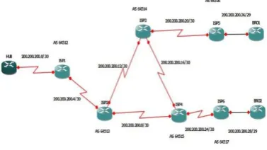
[image:3.595.58.265.337.478.2]The internet (or public network) was emulated by routers via Border Gateway Protocol (BGP). The public addresses were advertised by BGP across the routers which enables each router to be able to route packets to every other router’s public interface. EIGRP was used as the Interior Gateway Protocol (IGP) to enable routing of packets to one internal network from another internal network through the GRE tunneling. Internal networks were represented by loopback interfaces and each router has three loopback interfaces created on it, representing the internal LANs that are being emulated. DMVPN configurations were added to the network routers. The network diagram is shown in Figure 1 in segmented form.
Fig 1: Network Diagram in Segmented Form
Cisco c3700 series routers running on Cisco IOS were used and each ran on 128MiB of RAM and NVRAM of 55KiB size. The six ISPs routers and the hub router were connected via serial links. IP addresses were assigned dynamically via DHCP to the spokes. The interface module used is the NM-4T module for the serial links used to emulate WAN connections. The four-port synchronous (sync) serial network module (NM-4T) has four DB-60 ports and provides a data rate of 8 Mbps on port 0, 4 Mbps each on port 0 and port 2, or 2 Mbps on all four ports simultaneously. The NM-4T network module only supports sync mode. The DB-60 ports on the NM-4T network module support the Cisco60-pin "5-in-1"cables used on the Cisco 2500 and Cisco 7000 series routers [14]. Two types of IPv4 addresses used were public IP addresses in the 200.200.200.0/26 class C address space which were broken into smaller subnets used for the links between ISP routers in the cloud/internet network section, and also for the links between both the hub and each spoke to their respective ISPs; secondly, private IP addresses were used in the 10.10.10.0/24 for the GRE tunnel addressing, and 172.16.0.0/16, 172.17.0.0/16, 172.18.0.0/16 for the internal networks virtualized by the loopback interfaces on the hub and spoke routers. The addresses for the external interfaces of each spoke router were assigned dynamically via DHCP from their respective ISP’s router. The simulation environment had
Windows 7 OS running with 4GB of RAM memory and the simulator used was Graphical Network Simulator (GNS-3). Each spoke router had two addresses, internal addresses which emulate addresses for internal networks used in real-world settings, and the tunnel addresses. The second is an external address used for internet routing. Loopback interfaces were used to emulate internal networks in each branch router. The spokes’ external interfaces addressing was done dynamically using DHCP with the cloud router providing the dynamic addressing for each spoke router. This shows the ability of DMVPN to resolve changing addresses of branch routers. An IPSec profile created on both routers had a lifetime of 120 seconds thereby saving processor memory for other processes running on the router. Also, the tunnel interfaces make use of the pre-shared ISAKMP key to authenticate peer tunnels. Next hop resolution protocol (NHRP) was configured to map the public address of the hub router’s external interface to the tunnel IP address of the hub router. ISP1, which is the ISP that connects the hub router to the internet with the 200.200.200.0/30 address block, is connected to ISP2 via a serial link with the address block of 200.200.200.4/30 and so on. Each ISP router was assigned AS number in the range of private numbers assigned by the IANA. The cloud/internet routers in their AS groupings is as shown in Figure 2.
Fig 2: The Cloud Routers and their AS Numbers
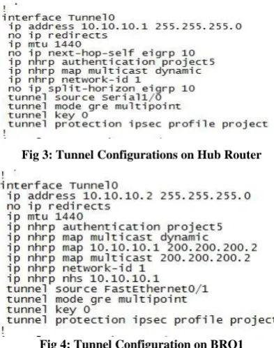
[image:3.595.334.523.354.460.2]Fig 3: Tunnel Configurations on Hub Router
Fig 4: Tunnel Configuration on BRO1
Several tests were carried out to verify the correct performance of the network setup. The command “show dmvpn” was used to verify DMVPN and tunnel connections setup running on the routers at that point in time while “show crypto isakmp sa” command verified the security-associations (SAs) of a specific router. Since the tunnels are all connected, a way to verify the setup of multipoint GRE (mGRE) was to test for the route advertisements received via EIGRP from the other DMVPN routers using the “show ip route eigrp” command. The Figures below (that is Figure 5 and Figure 6) show the results of the test carried out on the DMVPN routers.
[image:4.595.68.260.563.694.2]Fig 5: EIGRP Verification on Hub Router
Fig 6: EIGRP verification on BRO1
The “traceroute” shows that once the branch routers have established their first connection with each other through the hub, subsequent tunnel connections between the two routers are done directly, bypassing the hub router which drives home some of the reasons for the implementation of DMVPN
technology. Some of the many ping and traceroute results are shown in Figure 7 and Figure 8.
Fig 7: Ping and Traceroute Results from the Hub Router
Fig 8: Ping Command Results Traceroute from BRO1
In the event of a change in either or both of the branch router’s public interface address, results of tests performed in Figure 9 and Figure 10 show that once the interface is back up and creates a connection with the hub, the first ping attempt to it from the other remote router passes through the hub tunnel interface, after which all other ping attempts go directly to the router’s tunnel interface. This proves the flexibility and ability of DMVPN to withstand changing IP addresses among several spokes in a DMVPN network.
Fig 9: BRO1 obtains New IP Address
4.
RESULTS AND DISCUSSIONS
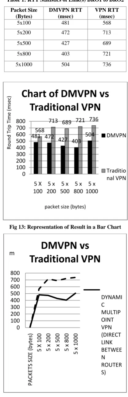
[image:5.595.322.531.84.729.2]The data gathered from running ping tests and capturing the round trip time (RTT) from both the DMVPN and traditional VPN network (without DMVPN implementation) are provided in Table 1 while two of the many RTT reports are as shown in Figure 11 and Figure 12 for the DMVPN and the traditional VPN respectively.
Fig 11: DMVPN RTT Statistics for 5 x 100bytes
Fig 12: Traditional VPN RTT Statistics for 5 x 800bytes
The same network topology was used to investigate the delay experienced by direct communication between the branch offices (in this case branch office 1 to 2) using the DMVPN compared with using the traditional VPN. Triangular routing issues is not yet fully resolved in traditional VPN routing but is prevented in the DMVPN by direct communication between the branch offices. The results obtained are represented statistically by a bar chart and line graphs in Figure 13 and Figure 14 respectively. It can be observed from the graph in Figure 16 that the delay experienced by the DMVPN is much less than that experienced by the ordinary VPN even as the traffic load (packet sizes) increases. Better performance is achieved by the DMVPN as a result of elimination of triangular routing for subsequent communication between branch offices after initial setup of communication channels. Also, as the packet size reached 1000bytes, the VPN experienced success rates having a mode of 40% for its ICMP echoes while the DMVPN had a much higher success rates over 95%.
Table 1: RTT Statistics of Link(s) BRO1 to BRO2
Packet Size (Bytes)
DMVPN RTT (msec)
VPN RTT (msec)
5x100 481 568
5x200 472 713
5x500 427 689
5x800 403 721
5x1000 504 736
Fig 13: Representation of Result in a Bar Chart
Fig 14: Line Graph Illustration of Results
481 472
427 403
504
568
713 689 721 736
0
100
200
300
400
500
600
700
800
5 X
100
5 x
200
5 x
500
5 x
800
5 x
1000
Ro
un
d
Tri
p
Ti
me
(msec)
packet size (bytes)
Chart of DMVPN vs
Traditional VPN
DMVPN
Traditio
nal VPN
0
100
200
300
400
500
600
700
800
PACKE
TS
SIZE
(b
ytes)
5
X 100
5
x 20
0
5
x 50
0
5
x 80
0
5
x 10
00
DMVPN vs
Traditional VPN
DYNAMI
C
MULTIP
OINT
VPN
(DIRECT
LINK
BETWEE
N
ROUTER
S)
[image:5.595.64.269.194.510.2]5.
CONCLUSION
A model that emulates live enterprise backend computer network communication infrastructure has been presented in this research. It showed how secure connections are made among enterprise routers in organizations branches spread across disparate geographical locations using DMVPN and its internal components such as mGRE, NHRP and IPSec technologies. Verifications and testing of the network functionality are carried out to validate that the network settings are flexible and adaptive to changing addresses of the public interfaces on remote branch routers, otherwise known as “spoke” routers. This model can be used as a back-up secure connection mode for Multi-Protocol label Switching (MPLS), so that during changes in the structures of ISP network devices over which the MPLS routes are defined, the systems could switch over to using the tunnels created by DMVPN. However, for much larger networks whether implemented with real gears or not, NHRP server load balancing could be implemented on both the primary hub and the secondary hub. Industry applications of VPN are virtual organizations, connection of distant clients to company’s network and military intelligence.
REFERENCES
[1] Paul Ferguson and Geoff Huston, “What is a VPN?”, Internet Protocol Journal, Volume 1, Number 1, 1998. Publisher: Cisco Press.
[2] Andrew Mason. CCSP Self-Study: Cisco Secure Virtual Private Networks (CSVPN), 2nd Edition, 2004. Publisher: Cisco Press.
[3] Sonam Wadhwa and Kunwar Pal. Providing Security in VPN by using Tunneling and Firewall, International Journal of Engineering and Advanced Technology (IJEAT), volume-2, February 2013.
[4] S. Saraswathi and P. Yogesh, “Mitigating Strategy to Shield the VPN Service from DoS Attack, International Journal on Cryptography and Information Security,Vol.2, No.2, June 2012.
[5] James V. Vuciani, “Next-hop resolution protocol”, Proc. SPIE 3233, Broadband Networking Technologies, 161 (October 6, 1997); doi: 10.1117/12.290456.
[6] Dynamic Multipoint VPN Configuration Guide, Cisco IOS release 12.4. Cisco Systems, 2011 © Cisco System Inc.
[7] Todd Lammle, Sean Odom, and Kevin Wallace. CCNP Routing Study Guide. ISBN: 0-7821-2712-6. Publisher: Cisco Press, 2001.
[8] Configuring Dynamic Multipoint VPN (DMVPN) using GRE over IPSec between Multiple Routers. Document
ID: 29240.
http://www.cisco.com/c/en/us/support/docs/security-vpn/ipsec-negotiation-ike-protocols/29240-dcmvpn.html [9] Dynamic Multipoint VPN (DMVPN) Design Guide
(Version 1.1). Cisco Press. © 2007 Cisco Systems, Inc. [10]ISAKMP Profile Overview. Cisco Press.
http://www.cisco.com/c/en/us/td/docs/ios/12_4/secure/co nfiguration/guide/h_isakp.pdf.
[11]RFC 2408. Internet Security Association and Key Management Protocol (ISAKMP). 1998.
[12]Andrew Mason. IPSec Overview Part Two: Modes and Transforms. Publisher: Cisco Press, 2002.
[13]Ohad Rodeh, Ken Birman, Mark Hayden, Danny Dolev. Dynamic Virtual Private Network. Department of Computer Science, Cornell University, 1995.
[14]Tomasz Malinowski and Artur Arciuch, “The procedure for monitoring and maintaining a network of distributed resources”, Proceedings of the 2014 Federated Conference on Computer Science and Information Systems, ACSIS, Vol. 2, pp. 947–954. DOI: 10.15439/2014F159.
[15]Ayoub Bahnasse & Najib EL Kamoun, “Policy-based Management of a Secure Dynamic and Multipoint Virtual Private Network” Global Journal of Computer Science and Technology: E-Network, Web & Security, Volume 14 Issue 8, 2014. Online ISSN: 0975-4172 & Print ISSN: 0975-4350.
[16]Adeyinka A. Adewale, Adagunodo E. R., John S. N., Ndujiuba C. U., “A Comparative Simulation Study of IP, MPLS, MPLS-TE for Latency and Packet loss Reduction over a WAN”, International Journal of Networks and Communications; p-ISSN: 4936 e-ISSN: 2168-4944, 2016; 6(1): 1-7. Doi:10.5923/j.ijnc.20160601.01.
[17]Adeyinka A. Adewale, Dike U. Ike, Ndujiuba Charles, John S. N,” Improvement of Quality of Service (QoS) over a Wide Area Network (WAN) using Multiprotocol Label Switching Traffic Engineering (MPLS-TE)”, International Journal of Computer Applications (IJCA) (0975 – 8887) Volume 88 – No. 10, February 2014, pp14-18.
[18]Adewale Adeyinka A., John Samuel N., Ndujiuba Charles, “A Simulation study of Effect of MPLS on Latency over a Wide Area Network (WAN)”, proceedings of the 2014 International Conference on Wireless Networks (ICWN), World Congress in Computer Science, Computer Engineering and Applied Computing (WORLDCOMP 2014), July 21-24, 2014, Las Vegas Nevada, USA, pp.196-201. ISBN: 1-60132-278-X.
[19]Adeyinka A. Adewale, Victor O. Matthews, Oboyerulu E. Agboje, Chinonso Okereke, David O. Ehigbochie, “IP Tunneling and Stateless DHCPv6 Implementation in an Enterprise Network”, International Journal of Scientific Research Engineering & Technology (IJSRET), June 2017, Volume 6, Issue 6, pp. 643-648. ISSN: 2278-0882. [20]N.M.M.K. Chowdhury, R. Boutaba, “A survey of
network virtualization”, Computer Networks, Vol. 54, Issue 5, pp. 862-876, 2009. ISSN: 1389-1286. Elsevier. Doi: 10.1016/j.Comnet.2009.10.017.