Autonomous Vehicle Density-based Traffic Control
System
Benjamin Kommey
Kwame Nkrumah University of
Science and Technology
Department of Computer
Engineering
Knust – Kumasi, Ghana
Seth Djanie Kotey
Kwame Nkrumah University of
Science and Technology
Department of Computer
Engineering
Knust – Kumasi, Ghana
Andrew Selasi Agbemenu
Kwame Nkrumah University of
Science and Technology
Department of Computer
Engineering
Knust – Kumasi, Ghana
ABSTRACT
Vehicular traffic congestion is an increasingly growing problem in this modern world. The increase in vehicles purchased per year in no way reduces the number of vehicles on our roads. There is therefore the need to devise a system to ensure smooth flow of vehicles, especially at intersections. Standard traffic lights, with fixed intervals between light changes, have helped reduce this issue over the years. However, the increase in the number of vehicles on roads, especially during rush hours, has rendered the standard traffic lights incapable of efficiently and effectively reducing traffic jams. In this paper, we present an autonomous vehicle density-based traffic control system. This traffic control system makes us of infrared sensors to determine the number of vehicles from each direction at an intersection and dynamically allocates traffic signal lights to ensure smooth and fair flow of vehicles at an intersection. The control system requires no human inputs and thus eliminates the possibility of human error. The system was designed and simulated using Proteus software.
Keywords
Infrared sensor, traffic light, autonomous, density-based, congestion.
1. INTRODUCTION
Vehicular traffic congestion is a major issue all over the world due to the increase in urbanization [1]. With the number of people owning vehicles increasing, this problem can only get worse with time. Aside this, traffic congestion contributes to environmental pollution and unpredictable travel times [2]. To curtail this problem, traffic lights were introduced. Much as the standard traffic lights have helped alleviate congestion on roads, they have at times been the culprits of congestion. Standard traffic lights ensure vehicles at an intersection proceed from each direction in a fixed amount of time [3]. This system does not take into consideration constantly changing traffic flow and the likelihood of an unbalanced density of vehicles waiting to proceed from each direction at the intersection. This causes the situation where there are no vehicles at a section of the intersection, yet there is a signal for vehicles from that section to proceed whilst other vehicles at the other sections have been signalled to wait. This causes an unnecessary waste of time at intersections and also contributes to traffic congestion, especially during rush hours [1].
There is therefore the need for an optimised traffic control system to deal with these problems. In this paper, we present an autonomous density-based traffic control system. Our proposed system determines vehicle density with the aid of infrared sensors positioned at each section of the intersection
and autonomously decides the best light designations to reduce traffic congestion at the intersection. The rest of the paper is organised as follows: related works are discussed in section 2, the proposed model is presented in section 3, testing and simulation is in section 4, results are presented in section 5 and the paper is concluded in section 6.
2. RELATED WORKS
Traffic congestion control is an issue of great concern in the modern world and different solutions have been proposed to combat it.
Gaikwad et al [4] proposed an image processing-based traffic control system which works by measuring the area covered by vehicles on the road. The system goes through three main process: image acquisition, transformation to grayscale and image enhancement. Green lines are drawn on the road at arbitrary distances which the camera has to detect. If parts of the lines are not detected, then there is a level of traffic on the road and the traffic lights are adjusted to suit the situation. The system was implemented using MATLAB software.
Ali et al. [5] proposed an autonomous road surveillance system (ARSS) using cameras. The system consists of cameras for image detection, a storage device for the images detected, an object detection algorithm, background object subtraction and shadow removal, blob segmentation and object classification. The system was designed to be integrated with existing video surveillance systems. For each lane, detected images are analysed and the blob ratio is used to determine the type of vehicle which has been detected. Based on the number of vehicles detected in all directions, the traffic lights are adjusted to ease congestion. Traffic control systems using cameras require storage space to store images and extra processing power to process images.
Promila Sinhmar [6] proposed an intelligent traffic using infrared sensors. The system is connected to a computer and is managed by an administrator.
In this paper, we present an autonomous traffic control system using infrared sensors. The system does not require special storage or processing capabilities and also does not require human input to function efficiently.
3. PROPOSED MODEL
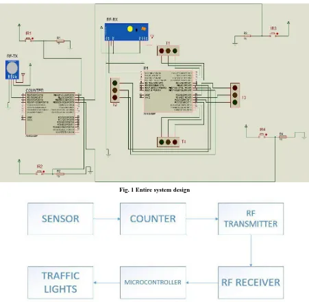
10 Figure 2 shows the block diagram of the interaction between
the components of the system. The infrared sensor is placed at a distance from the intersection. This enables vehicles moving towards the intersection to be counted. A suitable distance has to be chosen taking into consideration the volume of traffic that plies that route and the green light „on‟ time. Infrared sensors at each section only count vehicles when that section has a red light. This is to eliminate an inaccuracy of vehicle count when vehicles are moving out of the intersection during a green light period. All the infrared sensors are connected to the counter. The sensors detect when a vehicle moves past them. The counter records and increases the value for that sensor each time a vehicle moves past the sensor. After a set
[image:2.595.72.523.222.663.2]amount of time, the values for each section of the intersection are compared and a value is selected based on the comparison results. The value is transmitted to the central microcontroller (U1) via the RF transmitter and is reset, clearing all values previously recorded. Upon receiving the value from the counter, the central microcontroller automatically selects the lighting sequence corresponding to the value received. The red and green light „on‟ state for each light varies depending on the value received from the counter to ensure more vehicles from the congested section at the intersection are able to exit from the intersection.
Fig. 1 Entire system design
Fig. 2 Block diagram of system flow
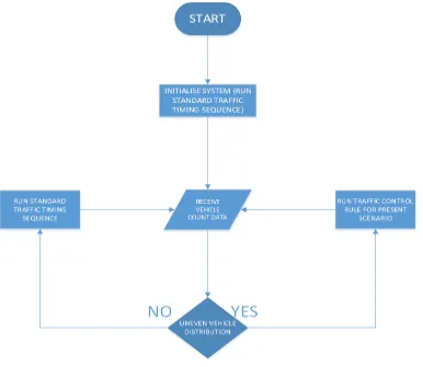
Figure 3 shows the flow of the algorithm. At the start of the system, with no input data, U1 runs the standard traffic light sequence, giving a fixed and equal time sequence of lights for each intersection. After the sequence is completed, U1 receives the vehicle count data from the counter. If there is an
Fig. 3 System flow sequence
4. TESTING AND SIMULATION
Proteus software was used to simulate the design. A switch was used in place of an infrared sensor for the simulation to mimic the signal generated by the infrared sensor when an object is detected.
To ensure the counter was operating as it should, a test circuit was modelled, shown in figure 4, which included an LCD to display the count operation. Figure 5 shows a screenshot of a running simulation.
[image:3.595.319.541.424.589.2]12
Fig.5 Running simulation
The system was designed for a simple intersection with the assumption that opposite sides of the intersection have their lights working together as a single pair. The highest recorded vehicle count between these two opposite sides is selected in the traffic light control decision process.
Nine different scenarios were used during our simulation.
1. Traffic lights 1 and 4 with more than or equal to 12 vehicles and traffic lights 2 and 3 with less than 6 vehicles allow a plus or minus 4 seconds in the sense that, the side with most vehicles gets an extra 4 seconds for vehicles to move whilst the side with less than 6 vehicles gets 4 seconds less of the standard time. The standard time for vehicular movement without any instance is a span of 8 seconds.
2. Traffic lights 1 and 4 with more than or equal to 12 vehicles and traffic lights 2 and 3 with more than 6 but less than 12 vehicles incorporate a plus or minus 2 seconds rule, where the former (side with more than or equal to 12 cars gets the extra 2 seconds)
3. Traffic lights 1 and 4 with more than or equal to 12 vehicles and traffic lights 2 and 3 with same number of cars experience the same length of time for green light delay (8 seconds)
4. Traffic lights 1 and 4 with less than 12 vehicles but more than or equal to 6 vehicles gets 2 seconds additional time whilst lights 2 and 3 with less than 6 cars get green light delay reduced by 2 seconds.
5. Traffic lights 1 and 4 with less than 12 vehicles but more than or equal to 6 vehicles experience the same time length for vehicular movement as traffic lights 2 and 3 with less than 12 cars but more than 6.
6. Traffic lights 2 and 3 with more than or equal to 12 vehicles experience an additional 4 seconds to regular time whilst traffic lights 1 and 4 with less than 6 vehicles experience a reduction in regular time by 4 seconds.
7. Traffic lights 2 and 3 with vehicles more than or equal to 12 observes an extra 2 seconds to the standard time as vehicles less than 12 but more than or equal to 6 observes a reduction in green light delay by 2 seconds with traffic lights 1 and 4.
8. Traffic lights 2 and 3 with vehicles less than 12 but more than or equal to 6 experience an additional 2 seconds to regular time as vehicles
less than 6 experience a reduction in green light delay by 2 seconds with traffic lights 1 and 4.
9. Any pair of traffic lights with no vehicle in its lane will see the other set of opposite traffic lights with at least one vehicle experiencing the green light display for the entire period.
5. RESULTS
The simulation of the system produced successful results. For each signal received by the counter, corresponding to a vehicle detected by the infrared sensor, the vehicle count was correctly updated. Data transfer via the RF transmitter-receiver pair was accurate and without any lag. For the scenarios tested, the traffic lights operated based on the values received by the counter without any errors.
The traffic light begins by running the standard traffic sequence. For each section having the red light on, the counter begins counting the vehicles detected by the infrared sensor. If the section has a green light, the counter does not count. The count is done only during the period when the traffic light is red for that section. After the initial run, which is 24 seconds, the result of the comparison between the vehicle count values is sent to the central microcontroller. Based on the value received, corresponding to the scenario, the traffic lights are lighted appropriately to allow for the more congested regions at the intersection to be eased of congestion.
6. CONCLUSION
Vehicular traffic congestion is an issue which is constantly being researched into to find solutions. In this paper, we have presented an autonomous density-based traffic control system to reduce vehicular traffic congestion on roads. Traffic density was determined using infrared sensors. The components proposed for the system are inexpensive and can operate with the existing traffic lights on our roads.
special memory requirements. The system was simulated and works well without errors.
The next step of this research work will be to implement a prototype for a real-world situation and test to determine its practicality.
7. REFERENCES
[1] K.Vidhya, A.Bazila Banu, “Density Based Traffic Signal System”, 2014.
[2] Basavaraju et al. “Vehicle Density Sensor System to Manage Traffic”, 2014.
[3] Vivek Tyagi, Shivkumar Kalyanaraman, Raghuram Krishnapuram “Vehicular Traffic Density State Estimation Based on Cumulative Road Acoustics”, 2012.
[4] Gaikwad et al., “Image Processing Based Traffic Light Control”, 2014.
[5] MD. Hazrat ALI, Syuhei KUROKAWA, A. A. SHAFIE, “Autonomous Road Surveillance System: A Proposed Model for Vehicle Detection and Traffic Signal Control”, 2013.