Table of Contents
Real-Time Design Patterns: Robust Scalable Architecture for Real-Time Systems
By Bruce Powel Douglass
Publisher : Addison Wesley Pub Date : September 27, 2002
ISBN : 0-201-69956-7 Pages : 528
When creating real-time and embedded (RTE) systems, there is no room for error. The nature of the final product demands that systems be powerful, efficient, and highly reliable. The constraints of processor and memory resources add to this challenge. Sophisticated developers rely on design patterns—proven solutions to recurrent design challenges—for building fail-safe RTE systems.
Real-Time Design Patterns is the foremost reference for developers seeking to employ this powerful technique. The text begins with a review of the Unified Modeling Language (UML) notation and semantics then introduces the Rapid Object-Oriented Process for Embedded Systems (ROPES) process and its key technologies. A catalog of design patterns and their applications follows.
Key topics covered in this book include:
• Identifying large-scale strategic decisions that affect most software elements • Coordinating and organizing system components and subsystems
• Managing memory and resources
• Defining how objects can be distributed across multiple systems • Building safe and reliable architectures
• Mapping subsystem and component architectures to underlying hardware
The book's extensive problem-solving templates, which draw on the author's years in the trenches, will help readers find faster, easier, and more effective design solutions.
The accompanying CD-ROM (Examples link) contains:
• Related papers
• Object Management Group (OMG) specifications
• Rhapsody(TM)—a UML-compliant design automation tool that captures the analysis and design of systems and generates full behavioral code with intrinsic model-level debug capabilities
• RapidRMA(TM)—a tool that integrates with Rhapsody(TM) to perform schedulability and timeliness analysis of UML models
TE
AM
FL
Y
Table of Content
Table of Content... i
Copyright... v
Dedication... vi
Foreword... vi
References... viii
Preface... viii
Goals... viii
Audience... viii
Organization... ix
More Information... ix
Acknowledgments... x
Part I: Design Pattern Basics... 1
Chapter 1. Introduction... 2
1.1 Basic Modeling Concepts of the UML... 2
1.2 Models... 3
1.3 Structural Elements and Diagrams... 4
1.4 Behavioral Elements and Diagrams... 21
1.5 Use Case and Requirements Models... 32
1.6 What Is a Design Pattern?... 34
References... 36
Chapter 2. Architecture and the UML... 37
2.1 Architecture... 37
2.2 Logical and Physical Architecture... 38
2.3 The Five Views of Architecture... 45
2.4 Implementing Architectures... 57
References... 63
Chapter 3. The Role of Design Patterns... 65
3.1 Introduction... 65
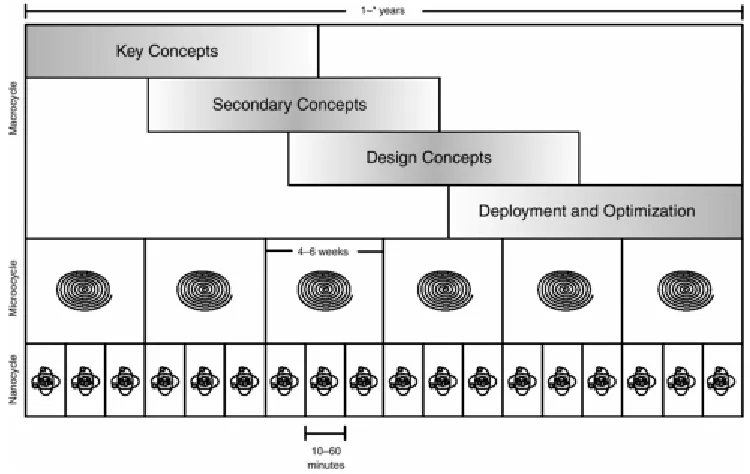
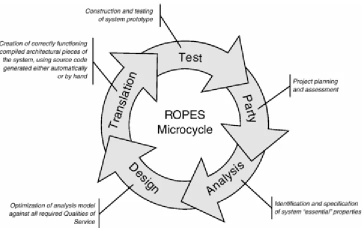
3.2 The ROPES Development Process... 65
3.3 Design Pattern Basics... 85
3.4 Using Design Patterns in Development... 89
References... 92
Part II: Architectural Design Patterns... 93
References... 94
Chapter 4. Subsystem and Component Architecture Patterns... 95
4.1 Layered Pattern... 95
4.2 Five-Layer Architecture Pattern... 99
4.3 Microkernel Architecture Pattern... 102
4.4 Channel Architecture Pattern... 106
4.5 Recursive Containment Pattern... 110
4.6 Hierarchical Control Pattern... 115
4.7 Virtual Machine Pattern... 118
4.8 Component-Based Architecture... 124
4.9 ROOM Pattern... 130
References... 136
Chapter 5. Concurrency Patterns... 137
iii
5.7 Cyclic Executive Pattern... 156
5.8 Round Robin Pattern... 159
5.9 Static Priority Pattern... 163
5.10 Dynamic Priority Pattern... 170
References... 174
Chapter 6. Memory Patterns... 176
6.1 Memory Management Patterns... 176
6.2 Static Allocation Pattern... 176
6.3 Pool Allocation Pattern... 180
6.4 Fixed Sized Buffer Pattern... 185
6.5 Smart Pointer Pattern... 189
6.6 Garbage Collection Pattern... 194
6.7 Garbage Compactor Pattern... 199
References... 204
Chapter 7. Resource Patterns... 205
7.1 Introduction... 205
7.2 Critical Section Pattern... 210
7.3 Priority Inheritance Pattern... 214
7.4 Highest Locker Pattern... 220
7.5 Priority Ceiling Pattern... 225
7.6 Simultaneous Locking Pattern... 231
7.7 Ordered Locking Pattern... 236
References... 241
Chapter 8. Distribution Patterns... 242
8.1 Introduction... 242
8.2 Shared Memory Pattern... 243
8.3 Remote Method Call Pattern... 248
8.4 Observer Pattern... 253
8.5 Data Bus Pattern... 258
8.6 Proxy Pattern... 267
8.7 Broker Pattern... 274
References... 279
Chapter 9. Safety and Reliability Patterns... 281
9.1 Introduction... 281
9.2 Protected Single Channel Pattern... 283
9.3 Homogeneous Redundancy Pattern... 287
9.4 Triple Modular Redundancy Pattern... 291
9.5 Heterogeneous Redundancy Pattern... 295
9.6 Monitor-Actuator Pattern... 299
9.7 Sanity Check Pattern... 303
9.8 Watchdog Pattern... 306
9.9 Safety Executive Pattern... 311
References... 315
Appendix A. Notational Summary... 317
Class Diagram... 317
Collaboration Diagram... 321
Sequence Diagram... 322
Use Cases... 323
Implementation Diagrams... 324
Package diagram... 325
Statechart... 326
Activity Diagrams... 330
v
Copyright
Many of the designations used by manufacturers and sellers to distinguish their products are claimed as trademarks. Where those designations appear in this book, and Addison-Wesley was aware of a trademark claim, the designations have been printed with initial capital letters or in all capitals.
The author and publisher have taken care in the preparation of this book, but make no expressed or implied warranty of any kind and assume no responsibility for errors or omissions. No liability is assumed for incidental or consequential damages in connection with or arising out of the use of the information or programs contained herein.
The publisher offers discounts on this book when ordered in quantity for bulk purchases and special sales. For more information, please contact:
U.S. Corporate and Government Sales
(800) 382-3419
For sales outside of the U.S., please contact:
International Sales
(317) 581-3793
Visit Addison-Wesley on the Web: www.awprofessional.com
Library of Congress Cataloging-in-Publication Data
Douglass, Bruce Powel.
Real-Time Design Patterns : robust scalable architecture for Real-time systems / Bruce Powel Douglass.
p. cm.—(The Addison-Wesley object technology series)
Includes bibliographical references and index.
(alk. paper)
1. Real-time data processing. 2. Software patterns. 3. Computer architecture.
I. Title. II. Series.
qa76.54 .D68 2003
004'.33—dc21
Copyright © 2003 by Pearson Education, Inc.
All rights reserved. No part of this publication may be reproduced, stored in a retrieval system, or
transmitted, in any form, or by any means, electronic, mechanical, photocopying, recording, or otherwise, without the prior consent of the publisher. Printed in the United States of America. Published
simultaneously in Canada.
For information on obtaining permission for use of material from this work, please submit a written request to:
Pearson Education, Inc.
Rights and Contracts Department
75 Arlington Street, Suite 300
Boston, MA 02116
Fax: (617) 848-7047
Text printed on recycled paper
1 2 3 4 5 6 7 8 9 10—CRS—0605040302
First printing, September 2002
Dedication
For Sarah. With all my heart, I dedicate this book and the following haiku to you.
Mist
cool forest mist
subdued hues, shrouded souls walking, touching, sigh
Foreword
vii
that regardless of the hardware costs, the software costs are a major part of the system costs (for example, software in a military or commercial aircraft). Barry Boehm, in his recent book updating the ubiquitous Cocomo software cost model [4], assigns an effort multiplier of 1.74 (the highest one) to all lifecycle phases of this latter kind of software, compared to "nominal" software (depending on the project
circumstances, that multiplier can easily be a major underestimation). Most real-time software lies between these two extremes, and it is that mainstream audience of practitioners who will benefit the most from this book.
Historically, developers of real-time software have lagged behind other developers in using the most contemporary software engineering methodologies. There are several reasons for this.
One is, as mentioned above, that some real-time software is so simple that only the most elementary methodologies are needed.
A more common reason is that many real-time systems with non-trivial software suffer from hardware capacity constraints (due to size, weight, power, and so on). Software structured for purposes such as re-usability, modularity, or flexibility does tend to consume additional time or space resources. This is sometimes compensated for by the fact that commodity computing system hardware cost is always
declining and its performance is always increasing. But in many real-time systems, hardware cost is still an easily measured quantitative factor that is thought to outweigh the hard-to-measure qualitative factors of software quality and costs.
Yet another reason is that real-time software practitioners are frequently application experts who are not always educated enough in modern software engineering to understand and employ it properly. New computer science and engineering graduates rarely enter the real-time field, because their formal education has not exposed them to much if any significant realistic real-time practice (real-time is a uniquely
disadvantaged aspect of computer science and engineering in this respect), and what little real-time theory they may have learned is still of very limited practical relevance.
This book provides an introduction to software patterns and the UML—by one of the most authoritative contributors to those topics—as applied to mainstream real-time software, in a manner that is easily understood by practitioners in that field without prerequisite knowledge. Those who make a modest investment in learning this material can expect to discover how to cast much of their hard-earned
professional experience in a framework that can make their real-time software designs more predictable— not just in terms of their timeliness (timeliness predictability being the raison d'être of real-time
computing), but also in terms of their lifecycle costs.
Another prospective benefit for many real-time software designers of becoming familiar with software patterns and the UML is that these issues are of rapidly increasing importance to building larger scale, more dynamic and complex, and more distributed real-time computing systems. Such systems offer highly significant (albeit as yet not always fully appreciated) added value to many enterprises, and hence offer perhaps the most challenging and rewarding career development opportunities in the field of real-time computing systems. This book is an excellent starting point toward that future.
—E. Douglas Jensen
Natick, Massachusetts July 2002
References
1. Boehm, Barry, Ellis Horowitz, Ray Madachy, Donald Reifer, Bradford Clark, Bert Steece, A. Winsor Brown, Sunita Chulani, and Chris Abts. Software Cost Estimation with Cocomo II. Upper Saddle River, NJ: Prentice Hall, January 2000.
2. Gamma, Erich, Richard Helm, Ralph Johnson, and John Vlissides. Design Patterns: Elements of Reusable Object-Oriented Software. Reading, MA: Addison-Wesley, 1995.
3. Lea, Doug. Design Patterns for Avionics Control Systems, http://st-www.cs.uiuc.edu/users/patterns/patterns.html, 1994.
4. OOPSLA 2001, Workshop on Patterns in Distributed Real-Time and Embedded Systems, ACM, October 2001.
Preface
Goals Audience Organization More Information Acknowledgments
Goals
ix
The book is oriented toward the practicing professional software developer and the computer science major in the junior or senior year. This book could also serve as an undergraduate- or graduate-level text, but the focus is on practical development rather than a theoretical dissertation. The book assumes a
reasonable proficiency in at least one programming language and a basic understanding of the fundamental concepts of object orientation, the Unified Modeling Language (UML), and real-time systems.
Organization
Part I consists of three chapters. Chapter 1 provides a very brief review of the major concepts in the Unified Modeling Language. Chapter 2 introduces the fundamental concepts of architecture as they are defined in the Rapid Object-oriented Process for Embedded Systems (ROPES), including the primary division of architecture into logical (design-time) and physical (run-time) aspects, and the five important architectural views. In the third chapter, the book gets into a discussion of design patterns and their role in defining architecture. Because it is difficult to discuss architecture in a process-free environment, the ROPES process, and the key technologies it tries to optimize, are introduced to provide a background in which design patterns may be effectively discussed. Once process has been introduced, design patterns are next. Their various aspects are explained, and the fundamental organization of design patterns used in this book is provided. The chapter finishes with a discussion of how design patterns can be applied in the development of real systems.
Part II contains the architectural design patterns that reify the ways that large-scale system components are organized and structured to optimize some set of general system criteria.
The patterns in Part II are organized around the architectural concept they address. Chapter 4 is dedicated to high-level structural patterns— focused around what is called the Subsystem or Component architecture. Because concurrency and resource management is so crucial to real-time and embedded systems, Chapter 5 focuses on the common patterns of concurrency. Memory management is crucial for many systems in this domain, and it is the subject of Chapter 6. We see even more general resource management patterns in
Chapter 7. Chapter 8 presents a number of common distribution architecture patterns that define how objects can be distributed across multiple address spaces and computers. Finally, Chapter 9 provides a number of patterns that deal with building safe and reliable architectures.
Two appendixes appear at the end of the book. The first is simply a summary of the UML graphical notation, and the second is an index of the patterns by name.
The CD-ROM provides a number of interesting and useful tools. It contains a full copy of the Rhapsody UML tool with instructions on how to get a temporary license from I-Logix. Other additional potentially useful tools for developers of real-time systems are also provided. The Papers chapter contains some papers on various topics as well as some useful OMG specifications.
More Information
Acknowledgments
A book like this is always a joint effort, not only of the direct contributors, such as the editorial staff of Addison–Wesley Professional (and I'd especially like to thank my editor, Paul Becker, for the sometimes less-than-gentle pushing to complete the book!) but of many others who in their own way have raised the bar for all of us. The core team members working on the UML—Cris Kobryn, Eran Gery, Jim Rumbaugh, Bran Selic, and many, many others are certainly among those who should be acknowledged in bringing forth a useful standard language for capturing and manipulating models of systems. Also, Erich Gamma, Richard Helm, Ralph Johnson, and John Vlissides deserve recognition for bringing the concept of design patterns into common use with their wonderful book Design Patterns: Elements of Reusable Object-Oriented Software. David Harel (inventor of statecharts, the semantic basis for all behavior in the UML) and Werner Damn continue to make significant contributions to the state of the art, especially with respect to formal verification of systems modeled with the UML.
1
Part I: Design Pattern Basics
Introduction
Several prerequisites are necessary to be successful in the application of design patterns into your own designs. First, in this book we will use the Unified Modeling Language (UML) to represent the patterns and the sample models. To make sure everyone starts on more or less the same footing, Chapter 1
introduces the basic semantics and notation of the UML. (Appendix A provides a notational summary for a quick reference.) Both structural and behavioral aspects are discussed well enough so that if you are a beginner, the patterns presented in Part I will at least make sense. It is not meant to be a full-blown UML tutorial—there are many other books available for that. If you need such a tutorial, then the reference section in Chapter 1 gives a list of suggested titles. Chapter 1 also talks a little about what a design pattern is and why its use is justified.
Once you know a little about the UML, it behooves us to understand what we mean by the term
architecture. There are many different uses of the term as applied to software, so Chapter 1 explains how the term is used in this book, including the two basic types of architecture (logical and physical) and within physical architecture, the important architectural views or aspects that are subject to pattern analysis.
Chapter 2 goes on to discuss how architectures may be implemented and describes the Model-Driven Architecture (MDA) initiative of the Object Management Group (OMG), the standards organization that owns the UML specification.
Once we have an understanding of architecture under our cognitive belts, the last thing we must understand before delving into the patterns per se is how patterns fit into design and how design fits into an overall development process. Of course, there are many different viable development processes, so this chapter will focus on one—the Rapid Object-oriented Process for Embedded System (ROPES)—and use this to explain how design in general, and patterns in particular, fit into the development of real-time and
embedded systems. The first part of Chapter 3 introduces the ROPES process, and the latter part discusses the structure and use of design patterns, including the identification, use, and application of design patterns.
TE
AM
FL
Y
Chapter 1. Introduction
This chapter discusses the following.
• Basic modeling concepts of the UML; overview of the UML; definition of design patterns • Class and object models—what they are; how classes and objects work together in collaborations;
collaborations; packaging of logical elements
• Component and deployment models; representing run-time artifacts and localizing them on processor nodes—State machines and behavioral models
• Use case and requirements models; capturing black-box behavior without revealing internal structure
1.1 Basic Modeling Concepts of the UML
The Unified Modeling Language (UML) is a third-generation object-modeling language standard, owned by the Object Management Group (OMG). The initial version of the OMG UML standard, 1.1, was released in November 1997. Since then, a number of minor revisions have been made. As of this writing, the current standard is 1.4 [1] and is available from the OMG at www.omg.org.
The response from the development community to the introduction of the UML has been overwhelming. The UML is now the de facto standard for software modeling. There are a number of reason for this, and it is the totality of all of them that, I believe, accounts for the phenomenal success of the UML.
First, the UML has a well-defined underlying semantic model, called the UML metamodel. This semantic model is both broad (covering most of the aspects necessary for the specification and design of systems) and deep (meaning that it is possible to create executable models that can be executed as-is or be used to generate source-level code for compilation). The upshot is that the developer can fairly easily model any aspect of the system that he or she needs to understand and represent.
Second, the notation used by the UML is easy to master and, for the most part, simple to understand. Although some people claim that the UML has too many diagrams, in reality there are only a few: structure (class) diagrams, deployment diagrams, statecharts, activity charts, and use case and sequence diagrams. They work in the obvious way and use a few common principles. Although the breadth of the notation can be a bit overwhelming to newcomers, in reality, complex systems can be easily developed with three core diagrams: class diagrams, statecharts, and sequence diagrams. The other diagrams can be used to model additional aspects of the system (such as capturing requirements or how the software maps onto the underlying hardware).
3
Last, the UML is applicable. Being a third-generation object-oriented modeling language, we now have person-centuries of experience applying object-oriented methods to the development of systems, including real-time and embedded systems. We have strengthened support for ideas that have worked well in the Darwinian world of systems development and removed those things that weren't useful. The UML is used today to model and build systems that vary in scope from simple one- or two-person projects up to those employing literally hundreds of developers. The UML supports all the things necessary to model timeliness and resource management that characterize real-time and embedded systems. That means that the developer need not leave the UML to design the different aspects of their system, regardless of how complex or arcane those things might be.
In this chapter, we introduce the basics of the UML. This is not meant to supplant other books about the UML but to provide enough information to understand and utilize the concepts and patterns that form the main content of this book. For a more in-depth discussion of the UML, the reader is referred to the references at the end of the chapter. Additionally, there are many whitepapers available on the I-Logix Web site: www.ilogix.com.
1.2 Models
The purpose of the UML is to allow the user to define a model of the system. A model is an integrated, coherent set of abstractions that represents the system to be designed. The model consists of both the semantics and the user views of those semantics. The important part of the user model is the definition of the semantics of the system under development. These semantics have three primary aspects: structural, behavioral, and functional. The structural aspect of the model identifies the "things" that make up the system. For example, a set of objects and their relations represents the state or condition of the system at some point in time—a "snapshot" view. The set of classes and their relationships specify the possible sets of objects and object relations that may exist at run-time. The difference is that the objects exist at run-time while the classes (being a specification) exist only at design time. At a larger scale, subsystems (basically big objects or classes) and components (also basically big objects or classes) form larger-scale abstractions for more complex systems. These concepts allow you to think about and manipulate the system at different levels of abstraction, which is required to build today's more complex and comprehensive systems.
The behavioral aspect of the model defines how the structural elements work and interact in the executing system. Behavior can be modeled and viewed for individual structural elements or for assemblies of structural elements working together to achieve larger-scale behaviors. For individual structural elements, such as objects, classes, subsystems, components, or use cases, the UML provides statecharts and activity diagrams to specify the actions and their permitted sequencing. Interactions are used to model how assemblies of structural elements, called collaborations, work together over time to achieve larger-scale behaviors. The UML uses two kinds of interaction diagrams: sequence and collaboration diagrams. Of these, sequence diagrams are by far more commonly used.
Finally, system functional aspects refer to required behavior without regard to the implementation of that behavior. In the UML, functional aspects are modeled as use cases; the detailed requirements of use cases are modeled using statecharts and interaction diagrams.
As mentioned previously, the application model consists of the semantics and all the views. The views reflect some particular set of the system semantics shown at some specific level of abstraction. The semantics are the sum of the semantics represented in the multitude of views, so it isn't necessary to show all the semantics in a single view. The views, however, are very useful. For one thing, they provide a very usable approach for the entry of the semantic information into the model. By drawing the classes on class diagrams, for example, we can define the structural semantics of that part of the system. By drawing the statechart for those classes, we enter the behavioral semantics for those elements. Thus, there is in principle a tight coupling between the set of diagrams you draw and the semantic model you construct of the system. That is one of the primary advantages of using a design automation tool as opposed to a drawing tool, such as Visio or Powerpoint. The design automation tool not only allows you to draw the diagrams but also manages the semantics of the application, making sure that they are consistent, performing checks on those semantics, and even validating the model through simulation or execution.
Now that we understand, in general terms, what a model is, let us discuss the semantic elements of the model and how to represent them on UML diagrams.
1.3 Structural Elements and Diagrams
The UML has a rather rich set of structural elements, and it provides diagrammatic views for related sets of them.
1.3.1 Small Things: Objects, Classes, and Interfaces
There are a number of elementary structural concepts in the UML that show up in user models: object, class, data type, and interface. These structural elements form the basis of the structural design of the user model. In its simplest form, an object is a data structure bound together with operations that act on that data. An object only exists at run-time; that is, while the system is executing, an object may occupy some location in memory at some specific time. The data known to an object are stored in attributes—simple, primitive variables local to that object. The behaviors that act on that data are called methods. These are the services invoked by clients of that object (typically other objects) or by other methods existing within the object.
A class is the design-time specification of a set of objects. That is, the objects are instances of the class. A class may have many instances in the system during run-time, but an object is an instance of only a single class. A class may specify a statechart that coordinates and manages the execution of its primitive behaviors (called actions, which are often invocations of the methods defined in the class) into allowable sets of sequences driven by the different events received. Statecharts are discussed later in this chapter.
5
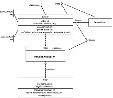
Figure 1-1 shows two other classes as well with a line (called an association—more on that later)
connecting them to the Sensor class. The first is the Filter class. This class offers services for filtering the data acquired by the Sensor class. It is shown in the figure using the same display format as the Sensor class. The other is the SensorClient class; its features are hidden. In this view, called the canonical form, only the class name is shown on the diagram. To view its features, it is necessary to browse the model repository or look on another diagram.
An interface is a named collection of operations. While it is not required to do usable modeling, interfaces allow you to separate out a set of services that may be called on a class from the implementation of those services. As we've seen, a class contains methods, which include the lines of code that implement the service. An operation is a specification of the service that does not include this implementation. To be well formed, the operation should define the signature for invoking the service, including the required
parameters and return value (if any), plus the preconditional and postconditional invariants of the operation. Preconditional invariants are things that must be true prior to the invocation of the service, while
postconditional invariants are things that the operation guarantees are true upon its completion.
Interfaces may not have attributes or methods, and they are not directly instantiable. A class is said to realize an interface if it provides a method for every operation specified in the interface and those methods have the same names, parameters, return values, preconditions and postconditions of the corresponding operations in the interface.
Interfaces are used to ensure interface compliance—that is, the client class can consistently and correctly invoke the services of a server class. There is another means to ensure interface compliance that uses the generalization relation from what is called abstract classes (classes that may not be directly instantiated). Abstract classes define operations but not methods, just as an interface does, and so may be used to ensure interface compliance. Either (or both, for that matter) approach can be used to ensure that the clients and servers connect correctly at run-time. Generalization and other class relations are discussed in the next section.
Of course, the UML model must ultimately map to source code. In Java and C++, the mapping is
straightforward. The source code for such a class diagram in Java is the most straightforward because Java contains interfaces as a native concept. The Java source code would look like the Java code in Code Listing 1.
Code Listing 1: Class Diagram in Java
public SensorClient {
protected myISensor iSensor; public void displayValue(void) {
int sensedValue = iSensor.getValue(); System.out.println(value);
};
}; // end class SensorClient
interface iSensor {
int acquire(void); int getValue(void);
void setCalibrationConstant(long newCalibrationConstant);
}; // end interface iSensor
public class Sensor implements iSensor { protected iFilter myIFilter;
int value;
long calibrationConstant;
public int acquire(void){ /* method here */ }; public int getValue(void) {
return myIFilter.filter(value); };
public void setCalibrationConstant(long newCalibrationConstant) {
calibrationConstant = newCalibrationConstant; };
}; // end class Sensor
interface iFilter {
public int filterValue(int value); }; // end interface iFilter
public class Filter implements iFilter { int lowPass;
7
highPass = newHighPass; };
}; // end class Filter
In C++, the code is almost as straightforward as the Java code, but not quite, because an interface is not a native concept in C++. There are two common approaches to implement interfaces is C++. The first, shown in Code Listing 2, is to create an abstract base class by declaring the interface operations as pure virtual. The other common approach is to use the Interface or Façade pattern. This involves creating the interface class as an instantiable class that associates to a separate implementation class.
Code Listing 2: Class Diagram in C++
class SensorClient { protected:
iSensor* myISensor; public:
void displayValue(void) {
int sensedValue = iSensor.getValue(); cout << value << endl;
}; };
class iSensor { // abstract class public :
virtual int acquire(void)=0; // pure virtual virtual int getValue(void)=0; // pure virtual virtual void setCalibrationConstant(long newCalibrationConstant)=0;
};
class Sensor : public iSensor { protected : iFilter* myIFilter; int value; long calibrationConstant; public : int acquire(void); int getValue(void){ return myIFilter->filterValue(value); }; void setCalibrationConstant(long newCalibrationConstant) { calibrationConstant = newCalibrationConstant; }; };
class iFilter { public :
virtual int filterValue(int value)=0; // pure virtual
};
class Filter : public iFilter { public :
int filterValue(int value) { lowPass = newLowPass; highPass = newHighPass; };
In summary, an object is one of possibly many instances of a class. A class has two notable features: attributes (which store data values) and methods (which provide services to clients of the class). Interfaces are named collections of operations that are realized by classes. Interfaces need not be explicitly modeled. Many useful systems have been designed solely with classes, but there are times when the additional level of abstraction is useful, particularly when more than a single implementation of an interface will be provided.
1.3.2 Relations
Classes, objects, and interfaces are little things. To do anything systemwide, many of these small things need to work together. And to work together, they must relate in some way.
1.3.2.1 Associations
The UML defines a number of different kinds of relations. The most important of these are association, generalization, and dependency. The most basic of these is called the association. An association is a design-time relation between classes that specifies that at run-time, instances of those classes may have a link and may be able to request services of one another.
The UML defines three distinct kinds of associations: association, aggregation, and composition. An association between classes means simply that at some time during the execution of the system, those objects may have a link that enables them to call or somehow invoke services of the other. Nothing is stated about how that is accomplished, or even whether it is a synchronous method call (although this is most common) or an asynchronous message transfer. Think of associations as conduits that allow objects at run-time to find each other and send messages. Associations are shown as lines connecting classes on class diagrams.
There are a number of aspects of an association between two classes that can be specified. For example, the ends of the associations may have role names. These name the instances with respect to the other class. It is a common practice to give the role name on the opposite end of the association to the pointer that points to that class. For example, in Figure 1-2, the Switch class might contain two pointers—one named primarySource and one named backupSource—that would be dereferenced at run-time to send the instance of the Charger and Battery classes messages, such as to enable or disable them.
9
Although somewhat less common, association labels may also be used, such as between the Power Subsystem and Display Subsystem classes. The label is normally used to help explain why the association exists between the two classes. In this case, the label "displays messages for" indicates that is how the Power Subsystem intends to use the Display Subsystem. To get the directionality of the label (is the Power Subsystem displaying messages for the Display Subsystem?), you can add an arrowhead next to the label to show the speaking perspective.
The multiplicity is probably the most important property of an association end. The multiplicity of an association end indicates the possible numbers of instances that can participate in the association role at run-time. This may be any of the following.
• A fixed number, such as "1" or "3"
• A comma-separated list, such as "0,1" or "3,5,7" • A range, such as "1..10"
• A combination of a list and a range, such as "1..10, 25", which means "one to ten, inclusive, or 25" • An asterisk, which means "zero or more"
• An asterisk with an endpoint, such as "1..*," which means "one or more"
Finally, the directionality of the association may be specified. A normal line with no arrowheads means that the association is bidirectional; that is, an object at either end of the association may send a message to an object at the other end. If only one of the objects can send a message to the other and not vice versa, then we add an open arrowhead (we'll see later that the type of arrowhead matters) pointing in the direction of the message flow. Thus, we see that a Switch object can send a message to a Battery object, but not vice versa. This does not imply that the Switch object cannot retrieve a value from a Battery object because it can call a method that returns a value. It means, however, that an object of type Battery cannot spontaneously send a message to a Switch object.
All of these adornments, except for perhaps multiplicity, are optional and may be added as desired to further clarify the relationships between the respective classes.
An association between classes means that at some point during the lifecycle of instances of the associated classes, there may be a link that enables them to exchange messages. Nothing is stated or implied about which of these objects comes into existence first, which other object creates them, or how the link is formed.
1.3.2.2 Aggregation
An aggregation is a specialized kind of association that indicates a "whole-part" relation exists between the two objects. The "whole" end is marked with a white diamond, as in Figure 1-2. For example, consider, the classes Message List and Message. The Message List class is clearly a "whole" that aggregates possibly many Message elements. The diamond on the aggregation relation shows that the Message List is the "whole." The "*" on the myMsg association end indicates that the list may contain zero or more Message elements. If we desired to constrain this to be no more than 100 messages, we could have made the multiplicity "0..100."
Since aggregation is a specialized form of association, all of the properties and adornments that apply to associations also apply to aggregations, including navigation, multiplicity, role names, and association labels.
Aggregation is a relatively weak form of "whole-part," as we'll see in a moment. No statement is made about lifecycle dependency or creation/destruction responsibility. Indeed, aggregation is normally treated in design and implementation identically to association. Nevertheless, it can be useful to aid in
understanding the model structure and the relations among the conceptual elements from the problem domain.
1.3.2.3 Composition
Composition is a strong form of aggregation in which the "whole" (also known as the "composite") has the explicit responsibility for the creation and destruction of the part objects. Because of this, the composite exists before the parts come into existence, and it exists after they are destroyed. If the parts have a fixed multiplicity with respect to the composite, then it is common to create those parts in its constructor (a special operation that creates the object) and destroy them in its destructor. With nonfixed multiplicities, the composite dynamically creates and destroys the part objects during its execution. Because the composite has creation and destruction responsibility, each part object can only be owned by a single composite object, although the part objects may participate in other association and aggregation relations. Composition is also a kind of association, so it can likewise have all of the adornments available to ordinary associations.
11
With the containment presentation, there is an issue as to how to show the multiplicity of the part (by definition, the multiplicity on the whole end of a composition is exactly "1"). Since there is no line on which to place the multiplicity, it is common to put the multiplicity in one of the upper corners of the part class. This is called instance multiplicity. We see that the Power Subsystem contains either one or two objects of type Switch, zero or more objects of type Charger, and zero to two objects of type Battery.
There is also the issue of how to show the role names. The common way is to use a class role name. A class role name precedes the class name and a slash (/) separator. In the figure, instances of class Switch have a class role name of PowerSwitch. As an aside, we can also show object names if we like,
independently from the class role names. An object name is shown as preceding the class name, with a colon (:) separator. Thus,
PowerSwitch/ thePowerSwitch: Switch
shows a role called PowerSwitch that is played by an object named thePowerSwitch, which happens to be an instance of class Switch.
The most common implementation of an association, as seen in the previous code examples, is an object pointer (in C++) or an object reference (in Java). This is true regardless of which kind of association it is, whether it is an ordinary association, an aggregation, or a composition. There are many other ways of implementing an association—including nested class declaration, object identifier reference (as in a MS Windows handle or a CORBA object ID), an operating system task ID, and so on—but using a pointer is the most common.
A Word About StereotypesFigure 1-2 has a couple of places where a class has a special adornment called a stereotype. A stereotype is a way of tailoring the UML to meet a specific need or purpose. It is part of the lightweight extension mechanism defined within the UML. A stereotype is a user-defined kind of element that is based on some already defined element in the UML, such as Class, Operation, Association, and so on. Stereotypes are usually shown by attaching the stereotype name in guillemets with the stereotyped element or shown using a user-defined icon. In the example figure, a class box is used for a large-scale element called a Subsystem. To indicate that this is that special kind of element, we attach the stereotype «subsystem» to the class box. Subsystems are discussed later in this chapter.
1.3.2.4 Generalization
The generalization relation in the UML means that one class defines a set of features that is either specialized or extended in another. Generalization may be thought of as "is a type of" relation and therefore only has a design-time impact rather than a run-time impact.
Generalization has many uses in class models. First, generalization is used as a means to ensure interface compliance, much in the same way that interfaces are used. Indeed, it is the most common way to implement interfaces in languages that do not have interfaces as a native concept, such as in C++. Also, generalization can simplify your class models because a set of features common to a number of classes can be abstracted together into a single superclass, rather than having to redefine the same structure
independently in many different classes. In addition, generalization allows for different realizations to be used interchangeably. For example, one realization subclass might optimize worst-case performance, while another optimizes memory size, while yet another optimizes reliability because of internal redundancy.
Generalization in the UML means two things. First, it means inheritance—that subclasses have (at least) the same attributes, operations, methods, and relations as the superclasses they specialize. Of course, if the subclasses were identical with their superclasses, that would be boring, so subclasses can differ from their superclasses in either or both of two ways: specialization or extension.
Subclasses can specialize operations or state machines of their superclasses. Specializing means that the same operation (or action list on the statechart) is implemented differently than in the superclass. This is commonly called polymorphism. In order to make this work, when a class has an association with another
TE
AM
FL
Y
that is a superclass, at run-time an instance of the first can invoke an operation declared in the second, and if the link is actually to a subclass instance, the operation of the subclass is invoked rather than that of the superclass.
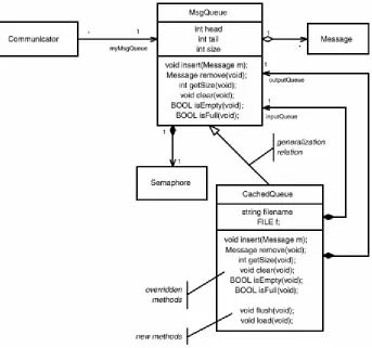
[image:22.595.130.473.307.628.2]This is much easier to see in the example presented in Figure 1-3. The class MsgQueue is a superclass, and it defines standard queue-like behavior, storing Message objects in a FIFO fashion with operations such as insert() and remove(). CachedQueue specializes and extends MsgQueue (the closed arrowhead on the generalization line points to the more general class). The Communicator class associates with the base class MsgQueue. If it needs to store only a few messages, a standard in-memory queue—that is, an instance of MsgQueue—works fine. But what if some particular instance of Communicator needs to store millions of messages? In that case, the instance can link to an instance of the CachedQueue subclass. Whether Communicator actually links to an instance of MsgQueue or one of its subclasses is unknown to the instance of Communicator. It calls the insert() or remove() operations as necessary. If the connected instance is of class MsgQueue, then the correct operations for that class are called. If the connected instance is of class CachedQueue, then the operations for that class are invoked instead, but the client of the queue doesn't know which is invoked.
Figure 1-3. Polymorphism
It is common not to show inherited methods in the subclass unless they override (redefine) methods inherited from the superclass, but this is merely a stylistic convention. Remember that a CachedQueue is a MsgQueue, so everything that is true about the latter is true of the former, including the attributes,
13
void MsgQueue::insert(Message m) { if (isFull())
throw OVERFLOW; else {
head = (head + 1) % size; list[head] = m;
}; };
However, the code for the insert operation in the subclass must be more complex. First, note that the subclass contains (via composition) two MsgQueues: one for input buffering and one for output buffering. The CachedQueue::insert() operation only uses the MsgQueue instance playing the inputQueue role. If this is full, then it must write the buffer out to disk and zero out the buffer. The code to do this is shown in
Code Listing 1-4.
Code Listing 1-4: CachedQueue::insert() operation
void CachedQueue::insert(Message m) { if (inputQueue->isFull()) {
// flush the full queue to disk and then // clear it flush();
inputQueue->clear(); };
inputQueue->insert(m); };
Similarly, the operations for remove(), getSize(), clear(), isEmpty(), and isFull() need to be overridden as well to take into account the use of two internal queues and a disk file.
Note that in the UML, attributes cannot be specialized. If the superclass defines an attribute of time sensedValue and it has a type int, then all subclasses also have that attribute, and it is of the same type. Subclasses can also extend the superclass—that is, they can have new attributes, operations, states,
transitions, relations, and so forth. If you need to change the type of an attribute, you should use the «bind» stereotype of dependency, discussed in Section 1.3.2.5.
The other thing that generalization means in the UML is substitutability. This means that anyplace an instance of the superclass was used, an instance of the subclass can also be used without breaking the system in any overt way. Substitutability is what makes generalization immensely useful in designs.
Figure 1-4 shows the previous queue example in a larger context. In this example, CachedQueue is still a subclass of MsgQueue. We see that MsgQueue also has a composition relation to a semaphore to ensure its integrity if it is called in the presence of multiple threads. We see the MsgQueue superclass has two different kinds of clients: end user clients (who want to send and receive messages), which are types of Communicating Object, and Communicators, which use the queue to do transmission and reception of the queues. Both of these are abstract, which means that they define at least one operation for which they do not supply a corresponding method. In C++ terms, they are pure virtual classes. The intended usage of these classes is that a class that wants to be able to send and receive messages will subclass from Communicating Object, and a class that wants to be able to use queues to perform transmission and reception will subclass Communicator.
1.3.2.5 Dependency
Association, in its various forms, and generalization are the really key relations defined within the UML. Nevertheless, there are several more relations that are useful. They are put under the umbrella of
dependency. The UML defines four different primary kinds of dependency: Abstraction, Binding, Usage, and Permission. Each of these may be further stereotyped. For example, «refine» and «realize» are both stereotypes of the Abstraction relationship, and «friend» is a stereotype of Permission. All of these special forms of dependency are shown as a stereotyped dependency (dashed line with an open arrowhead).
Arguably, the most useful stereotypes of dependency are «bind», «usage», and «friend». Certainly, they are the most commonly seen, but there are others. The reader is referred to [1] for the complete list of "official" stereotypes.
15
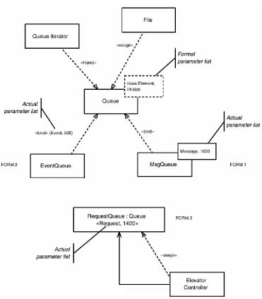
[image:25.595.112.483.188.611.2]Queue is a parameterized class that is defined in terms of two symbolic elements: a class called Element and an int called Size. Because the exact elements that these parameters refer to are not provided in the definition of Queue, Queue is not an instantiable class; those undefined elements must be given definitions. The «bind» dependency does exactly that—binding a list of actual elements to the formal parameter list. In the case of MsgQueue, Element is replaced by the class Message, and the int Size is replaced by the literal constant 1000. Now that the actual parameters are specified and bound, MsgQueue is an instantiable class, meaning that we can create objects of this class at run-time.
Figure 1-5. Dependency
The diagram shows three common forms for showing the «bind» dependency. Form 1 is the most common, but the other forms are prevalent as well.
The Permission relation grants permission for a model element to access elements in another. The «friend» stereotype is a common one between classes, modeling the friend keyword in C++. «access» is similar to Ada's use keyword, granting access of a namespace of one Ada package to another. The «import» relation adds the public elements of one namespace (such as a UML package) into another.
1.3.3 Structural Diagrams
UML is a graphical modeling language, although, perhaps surprisingly, the notation is nonnormative for the language. Nevertheless, there is a common set of graphical icons and idioms for creating these views of the underlying model. We call these views "diagrams." UML has been unjustly criticized for having too many diagram types—class diagrams, package diagrams, object diagrams, component diagrams, and so on. The fact is that these are all really the same diagram type—a structural diagram. Each of these diagrams emphasizes a different aspect of the model, but they may each contain all of the elements in the others. A package diagram may contain classes, and a class diagram may contain objects, whereas a component diagram might have objects, classes, and packages. In truth, the UML has a structural diagram that we call by different names to indicate the primary purpose of the diagram.
We use diagrams for a number of different purposes: as a data entry mechanism, as a means to understand the contents of the model, and as a means to discuss and review the model. The model itself is the totality of the concepts in your system and their relations to one another. When we use diagrams as a data entry mechanism, we add, modify, or remove elements to the underlying model as we draw and manipulate the diagrams.
The most common diagrams you'll draw are the class diagrams. These diagrams emphasize the organization of classes and their relations. The other aspects are drawn as needed, but class diagrams provide the primary structural view.
In real systems, you really cannot draw the entire system in a single diagram, even if you use E-size plotter paper and a 4-point font. As a practical matter, you must divide up your system into different structural views (behavioral views will be described later). How, then, can we effectively do this? What criteria should we use to decide how many diagrams we need and what should go on them?
In the ROPES process [3], we use a simple criterion for decomposing the views of the system into multiple diagrams. The ROPES process introduces the concept of a mission of an artifact—its "purpose for
existence." For diagrams, the mission is straightforward: Each diagram should show a single important concept. This might be to show the elements in a collaboration of objects or classes realizing a use case, or a generalization taxonomy, or the contents of a package. Usually, every element of your model appears in some diagram somewhere, but it is perfectly reasonable for it to appear in several diagrams. For example, a class might be involved in the realization of three use cases (resulting in three different diagrams), be a part of a generalization taxonomy, and also be contained in a package of your model. In this case, one might expect it to appear in five different diagrams. It is also not necessary for all aspects of the class to be shown in all views. For example, in the class diagrams showing collaborations, only the operations and attributes directly involved in the mission of that collaboration would be shown; in a diagram showing generalization, only the features added or modified by that class would be shown; in a diagram showing the contents of the package that owns the class, you probably wouldn't show any attributes or operations.
17
1.3.4 Big Things: Subsystems, Components, and Packages
Classes, objects, and interfaces are little things. It takes collaborations of many of them to have
systemwide behavior. Because of the complexity of today's systems, it is unusual to find a system that can be effectively developed and managed without thinking about larger-scale structures. The UML does provide a number of concepts to manage systems in the large scale, although most of the literature has not effectively explained or demonstrated the use of these features. And, to be honest, the UML specification does not explain them and how they interrelate very well either.
Since the focus of this book is architectural design patterns, we will use these concepts extensively in the patterns that form the bulk of this book, so it behooves us to be clear and precise about these concepts and how we'll apply them.
Packages are model elements that can contain other model elements, including other packages. Packages are used to subdivide models to permit teams of developers to manipulate and work effectively together. Packages cannot be instantiated and can only be used to organize models. They do define a namespace for the model elements that they contain, but have no other semantics. The UML does not provide any criterion as to whether a class should go in this package or that; it merely provides packages as a model building block to aid in whatever organizational purpose the developer desires.
The ROPES process recommends that packages be used with a specific criterion: "common subject matter or common vocabulary." This is similar to the Shaler and Mellor concept of a domain, and the ROPES process uses the stereotype «domain» to indicate this particular usage of packages. Indeed the Layered Architecture Patterns in Chapter 4 use «domain» packages to organize a model. This is a special case in which the subsystem organization maps one-to-one to the package structure. However, packages can be used to organize the application model in any desired way.
A package normally contains elements that exist only at design-time— classes and data types—but may also contain use cases and various diagrams, such as sequence and class diagrams. These design pieces are then used to construct collaborations that realize systemwide functionality. Packages are normally the basic Configuration Items for a configuration management tool, rather than the individual classes. Figure 1-6 shows that packages are drawn to look like a tabbed folder and may optionally show the elements that they semantically contain.
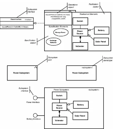
Subsystems are different animals, although in the UML 1.4 they are partially based on packages. A Subsystem is a stereotype of both Package and Classifier. This makes subsystems instantiable, meaning that you can create an instance of the type that occupies memory at run-time. A subsystem is used to organize the run-time system consisting of instances; the criterion for inclusion in a subsystem is "common behavioral purpose." The real work of a subsystem is implemented by the run-time instances contained within the subsystem; the subsystem offers up the collaborative behavior of those elements. Subsystems don't do any "real work" in and of themselves. The "real work" is done by what is sometimes called the semantic objects of the system—the primitive objects that actually perform the bottom-level functionality. A subsystem is at a higher level of abstraction of the system than these primitive semantic objects, and this level of abstraction allows us to view and manipulate the structure and behavior of complex systems much more easily.
19
[image:29.595.114.482.143.564.2]Subsystems as a stereotype of Class as well. And, in fact, this is a common way to show subsystems— showing the run-time instances that do the real work of the subsystem as being contained via the composition relation between classes, as shown at the bottom of the figure.
Figure 1-7. Subsystems
Like the metatype Class, a Component is also a kind of Classifier; it can have methods that realize interfaces, have statecharts and use cases. It is used to represent the replaceable pieces of the system. Typically, components have language-independent opaque [1] interfaces and may have «usage»
dependencies on other components. Components are coarse-grained elements that are usually replaced as a whole in the application. Components usually fit into a component framework, such as COM+, CCM (CORBA Component Model), or EJB. These component frameworks provide the means to load or unload the components as needed and standard ways for components to find each and to invoke services on them. As the UML 1.4 specification states, "There are only subtle differences between the semantics of
components and classes."
[1] By "opaque" we mean that the underlying implementation is not visible, just a way to invoke the service.
TCP/IP protocol stacks, or databases, or they may be specially constructed, such as configuration tables or static or dynamic link libraries. In typical usage, they are also designed to work within a specific
component framework, and this is less true with subsystems. Finally, Component-Based Development (CBD) approaches use the metaphor of construction through assembly (of existing parts) rather than construction via invention. Where possible, CBD can provide a tremen-dous savings of effort and time. That presumes, of course, that the component framework runs on your target hardware environment, suitable components are available for you to purchase, and these components meet your quality of service constraints, such as worst-case performance, memory size, and predictability.
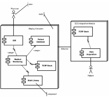
[image:30.595.114.483.338.665.2]Often, components and subsystems are mixed in with the deployment model, particularly for asymmetric deployment architectures—that is, where the processor location of a component or subsystem is known at design time. Nodes are the only three-dimensional icon in the UML notation and represent the hardware environment on which one or more software entities run (the «processor» node stereotype) or a piece of hardware that is just used but doesn't itself execute software that you write (the «device» node stereotype).
Figure 1-8 shows components with the «usage» stereotype. In the figure, the components are placed on processor nodes, but this isn't necessary. Note also the stick figure in Figure 1-8. This is called an actor. An actor is an object that is outside the scope of concern but interacts with the element under development in ways that we care about. We will see actors used more extensively later in the section about use cases and requirements modeling.
Figure 1-8. Components
21
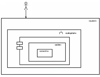
[image:31.595.121.472.168.437.2]example, you may have multiple layers of subsubsystems before you get to the Component level. For simpler systems, you may not require all of these levels. You might skip Subsystem level and just have Components. You may even find that for very simple systems, you need only the System, «active» objects, and semantic objects. Your mileage may vary in terms of how you apply these concepts, but I have found this a useful way to use the organizational concepts in practice. This size hierarchy is shown in Figure 1-9.
Figure 1-9. System, Subsystem, Component, and Active Objects Organized by Size
1.4 Behavioral Elements and Diagrams
What we've discussed so far is the definition of structural elements of the system: classes and objects (in the small) and systems, subsystems, and components (in the large). As developers, we are usually even more concerned about how these structural elements behave dynamically as the system runs. Behavior can be divided up into two distinct perspectives: how structural elements act in isolation and how they act in collaboration.
In the UML metamodel, ModelElements are the primary structural elements that have behavior. Classifiers (which are types of ModelElements) also have BehavioralFeatures, specifically Operations, and the realization of operations, Methods. In practice, we are primarily concerned with the specification of the reactive behavior of only certain Classifiers (classes, objects, subsystems, components, and use cases) and certain other ModelElements (Actions, Operations, and Methods).
1.4.1 Actions and Activities
An action is "a specification of an executable statement that forms an abstraction of a computational procedure that results in a change in the state of the model, and can be realized by sending a message to an object or modifying a link or a value of an attribute" [1]. That is, it is a primitive thing, similar in scope to a single statement in a standard source-level language, such as "++X" or "a=b+sin(c*PI)". The UML 1.4 specification identified a number of different kinds of actions such as the following.
• CreateAction— action that results in the creation of an instance
TE
AM
FL
Y
• CallAction— action that results in the synchronous invocation of an Operation or Method • ReturnAction— action that results in the synchronous return of control to a caller Operation,
Method, or Action
• SendAction— action that results in the asynchronous transmission of an event • TerminateAction— action that terminates the behavior of an ActionSequence • DestroyAction— action that results in the destruction of an instance
• UninterpretedAction— action that does something unspecified • ActionSequence— action that has parts, each of which is an action
Actions are normally computationally simple things and, by far, are most commonly represented using an action language. The UML does not define an action language because most developers want to use the implementation source level language for the action language. That is, almost all of the time, actions in a UML model are provided in the implementation language of that system. A more abstract action language is possible, providing the ability to generate code in multiple target languages, but the UML does not define one.
Actions have "run-to-completion" semantics, meaning that once an action is started, it will run until it is done. This does not mean that an action cannot be preempted by another action running in a higher-priority thread, only that when the context executing that action returns from preemption, it will continue executing that action until it is complete. This means that if an object is executing an action, that action will run to completion even if that object receives events directing it to do something else. The object will not accept the incoming events until the action has completed.
An Activity is an action that runs when a Classifier is in a state and is terminated either when it is complete or when the Classifier changes state. That is, Activities do not have run-to-completion semantics. An object executing an activity may receive an event that triggers a transition, exiting the state and terminating the activity. Thus, the UML allows the modeling, at a primitive level, both interruptable and
noninterruptable behaviors.
1.4.2 Operations and Methods
An Operation is a specification of an invocable behavior of a Classifier, whereas a Method is the implementation of an Operation. That is, an Operation is a specification of a Method. Operations are synchronously invoked and are logically associated with CallEvents in the UML metamodel. Operations have typed parameter lists, as you might expect, and can return typed values. It is common to use an operation call as an action on a state behavior.
Modeling of the behavior of an operation is done primarily in two ways. First, and most common, is to simply list, in a textual fashion, all of the actions comprising the internals of the operation or method. The second, which will be described shortly, is to model the operation with a synchronous state machine or with an activity diagram.
1.4.3 Statecharts
A finite state machine (FSM) is a machine specified by a finite set of conditions of existence (called "states") and a likewise finite set of transitions among the states triggered by events. An FSM constrains the behavior of a model element by explicitly stating which events are handled for each of the states of that element, as well as what actions are performed under what conditions.
23
• Nested states for specifying hierarchical state membership • And-states for specifying logical independence and concurrency
• Pseudostates for annotating commonly needed specific dynamic semantics
Figure 1-10 shows some of the basic elements of a statechart—basic or-states and transitions—as well as a few less elementary concepts, including nested states and conditional, initial, and terminal pseudostates.
Figure 1-10. Simple Statechart
Transitions are arrowed lines coming from a predecessor state and terminating on a subsequent state. Transitions usually have the optional event signature and action list. This is the basic form of an event signature.
event-name '('parameter-list')' '['guard']' '/' action-list
The event-name is simply the logical name of the event class that may be sent to an instance of the Classifier at run-time, such as "Send" or "tm" in Figure 1-10. The UML defines four distinct kinds of events that may be passed or handled.
• SignalEvent— an asynchronously sent event • CallEvent— a synchronously sent event
• TimeEvent— an event due to the passage of an interval of time (most common) or arrival of an epoch
• ChangeEvent— a change in a state variable or attribute of the Classifier
complete. This is commonly implemented by invoking a class method called an event handler that executes the relevant part of the state machine, returning control to the sender only when the event processing is complete.
Events may have parameters, which are typed values accepted by the state machine that may then be used in the guard and actions in the processing of the event. The statechart specifies the formal parameter list, while the object that sends the event must provide the necessary actual parameters to bind to the formal parameter list.
Time events are almost always relative to the entry to a state. A common way to name such an event (and what we will use here) is "tm(interval)," where "interval" is the time interval parameter for the timeout event. If the timeout occurs before another specified event occurs, then the transition triggered by the timeout event will be taken. If another event is sent to the object prior to the triggering of the timeout, then the timeout is discarded. If the state is reentered, the timeout interval starts over from the beginning.
If a transition does not provide a named event trigger, then it is activated by the "completion" or "null" event. This event occurs either as soon as the state is entered (which includes the execution of entry actions for the state) or when the activities complete, if the state declares activities to be executed.
A guard is a Boolean expression that returns only TRUE or FALSE and does not have side effects. If a guard is specified for a transition, then if the event trigger (if any) occurs, then the transition will be taken if and only if the guard evaluates to TRUE. If the guard evaluates to FALSE, then the triggering event is quietly discarded.
The action list for the transition is executed if and only if the transition is taken. That is, the named event is received by the object while it is in the predecessor state, and the guard, if any, evaluates to TRUE. The entire set of actions—that is exit actions, transition actions, and entry actions—is executed in that order and is executed using run-to-completion semantics, as noted previously.
In addition to entry and exit actions, states may also have activities that, as noted previously, are actions that may be interrupted by incoming events that trigger named reactions in the specified state.
Figure 1-11 shows an important additional concept in statecharts: and-states. While or-states are disjoint and exclusive, and-states are disjoint but not nonexclusive. Given a set of or-states, the object must be in one and only one or-state in a state context. Given a set of and-states, the object must be in every active and-state simultaneously. In Figure 1-11, the object only has a single high-level state: Operating. The Operating state, however, has two and-substates: Processing and Testing. The fact that these are and-states is denoted with the dashed-line separating them.