organic papers
o1040
Brendan Twamleyet al. C5H3F3N2O2 DOI: 10.1107/S1600536802015295 Acta Cryst.(2002). E58, o1040±o1042 Acta Crystallographica Section EStructure Reports Online
ISSN 1600-5368
5-(Trifluoromethyl)uracil
Brendan Twamley,a* O. D. Guptab and Jean'ne M. Shreeveb
aUniversity Research Office, 114 Morrill Hall, University of Idaho, Moscow, ID 83844-3010, USA, andbDepartment of Chemistry, University of Idaho, Moscow, ID 83844-2343, USA
Correspondence e-mail: [email protected]
Key indicators Single-crystal X-ray study
T= 213 K
Mean(C±N) = 0.003 AÊ
Rfactor = 0.049
wRfactor = 0.105
Data-to-parameter ratio = 11.1
For details of how these key indicators were automatically derived from the article, see http://journals.iucr.org/e.
#2002 International Union of Crystallography Printed in Great Britain ± all rights reserved
The title compound, 5-tri¯uoromethyl-1H-pyrimidine-2,4-dione, 5-CF3-C4H3N2O2or C5H3F3N2O2, (I), displays marked
differences in packing compared to the non-¯uorinated parent molecule, 5-CH3-C4H3N2O2,i.e.thymine. Compound (I) forms
a complicated three-dimensional array using hydrogen bonds [range 2.808 (3)±2.814 (3) AÊ], resulting in channels or voids parallel to [001], which are lined with F atoms from the CF3
groups.
Comment
Compound (I), 5-CF3-C4H3N2O2 (Fig. 1), is a partially
¯uorinated derivative of thymine. This compound has proven extremely useful in our continued research into ¯uorine chemistry (Gupta, Kirchmeier & Shreeve, 2000; Gupta, Twamleyet al., 2000).
The structure of non-¯uorinated thymine is well known (Ozekiet al., 1969; Portaloneet al., 1999); it crystallizes in the common space groupP21/c. In the solid state, the structure
consists of planar sheets of thymine molecules held together by hydrogen bonding, with the molecules facing head-to-head. Sheets are stacked on top of each other, forming a regular array. Hydrogen-bond values are in the range 2.810±2.836 AÊ.
Received 20 August 2002 Accepted 27 August 2002 Online 31 August 2002
Figure 1
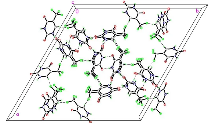
When the methyl group is ¯uorinated, the packing changes dramatically. Compound (I) now crystallizes in the trigonal space groupR3 and the hydrogen-bonded sheet motif is no longer observed. In this case, a complicated three-dimensional `in®nite' array is formed, with the uracil molecules hydrogen-bonding in pair-units, head-to-tail and side-by-side. These units are essentially planar with an out-of-plane r.m.s. devia-tion of 0.0241 AÊ (for all non-F atoms including H atoms). These pair-units then hydrogen bond to four other pair-units (Table 1). A section of the packing is shown in Fig. 2. This packing arrangement causes the CF3 groups to form a
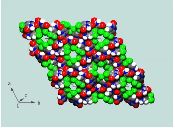
symmetry-imposed pseudo-hexagonal channel. The F atoms become the lining for the channel, which is approximately 3.6 AÊ wide and extends parallel to [001]. The volume of these channels in the unit cell is approximately 50 AÊ3. Fig. 3 displays
these channels outlined in green. The orientation of the CF3
groups brings an F atom into close proximity to an H atom [H6A F3iii; symmetry code: (iii)xÿy,x, 1ÿz] of a
neigh-boring molecule. There is also a close intramolecular contact with the same H atom (F1 H6A). These distances are
recorded in Table 1. Although these values are within the sum of the van der Waals radii of both ¯uorine and hydrogen, whether these are weak interactions is questionable. Inter-molecular distances ofd< 2.35 AÊ (d= H F intermolecular distance) are generally accepted to be `true' weak hydrogen-bonding interactions (Desiraju & Steiner, 2001).
Experimental
The sample was obtained commercially from Fluorochem (Cat. No. 3333), and recrystallized from CH3CN.
Crystal data C5H3F3N2O2
Mr= 180.09
Trigonal,R3
a= 25.5695 (17) AÊ
c= 5.1934 (5) AÊ
V= 2940.5 (4) AÊ3
Z= 18
Dx= 1.831 Mg mÿ3
MoKradiation Cell parameters from 2171
re¯ections
= 2.8±23.3
= 0.20 mmÿ1
T= 213 (2) K Fragment, colorless 0.350.250.15 mm Data collection
Bruker SMART 1K CCD diffractometer
!scans
Absorption correction: multi-scan (SADABS; Sheldrick, 2001)
Tmin= 0.935,Tmax= 0.971
12 551 measured re¯ections
1208 independent re¯ections 896 re¯ections withI> 2(I)
Rint= 0.045
max= 25.5
h=ÿ30!27
k=ÿ28!30
l=ÿ6!6 Re®nement
Re®nement onF2
R[F2> 2(F2)] = 0.049
wR(F2) = 0.105
S= 1.09 1208 re¯ections 109 parameters
H-atom parameters constrained
w= 1/[2(F
o2) + (0.0361P)2
+ 5.2597P]
whereP= (Fo2+ 2Fc2)/3
(/)max< 0.001
max= 0.20 e AÊÿ3
min=ÿ0.24 e AÊÿ3
Table 1
Hydrogen-bonding geometry (AÊ,).
DÐH A DÐH H A D A DÐH A
N1ÐH1A O1i 0.87 2.03 2.808 (3) 148
N3ÐH3A O2ii 0.87 1.94 2.814 (3) 176
C6ÐH6A F1 0.94 2.35 2.697 (3) 101 C6ÐH6A F3iii 0.94 2.41 3.337 (3) 169 Symmetry codes: (i)1
3ÿxy;23ÿx;23z; (ii)23ÿx;13ÿy;ÿ23ÿz; (iii)xÿy;x;1ÿz.
H atoms were positioned geometrically and re®ned using a riding model, withUisovalues constrained to be 1.2Ueqof the carrier atom.
Data collection:SMART(Bruker, 1999); cell re®nement:SMART; data reduction: SAINT±Plus (Bruker, 1999); program(s) used to solve structure:XSinSHELXTL(Sheldrick, 2001); program(s) used to re®ne structure: XL in SHELXTL; molecular graphics: XP in
SHELXTL; software used to prepare material for publication:XCIF
inSHELXTL.
The Bruker (Siemens) SMART CCD diffraction facility was established at the University of Idaho with the assistance of the NSF±EPSCoR program and the M. J. Murdock Charitable Trust, Vancouver, WA, USA. The authors thank A. Vij for collecting the data.
Acta Cryst.(2002). E58, o1040±o1042 Brendan Twamleyet al. C5H3F3N2O2
o1041
organic papers
Figure 2
A ball-and-stick packing diagram of (I). Hydrogen bonding is indicated by dashed lines.
Figure 3
organic papers
o1042
Brendan Twamleyet al. C5H3F3N2O2 Acta Cryst.(2002). E58, o1040±o1042References
Bruker (1999). SMART(Version 5.025) and SAINT-Plus (Version 5.01). Bruker AXS Inc., Madison, Wisconsin, USA.
Desiraju G. R. & Steiner, T. (2001).The Weak Hydrogen Bond In Structural Chemistry and Biology, IUCr Monograph No. 9. Oxford University Press. Gupta, O. D., Kirchmeier, R. L. & Shreeve, J. M. (2000).Inorg. Chem.39, 117±
120.
Gupta, O. D., Twamley, B., Kirchmeier, R. L. & Shreeve, J. M. (2000).J. Fluorine Chem.106, 199±204.
Ozeki, K., Sakabe, N. & Tanaka, J. (1969).Acta Cryst.B25, 1038±1045. Portalone, G., Bencivenni, L., Colapietro, M., Pieretti, A. & Ramondo F.
(1999).Acta Chem. Scand.53, 57±59.
Sheldrick, G. M. (2001).SHELXTL.Version 6.10. Bruker AXS Inc., Madison, Wisconsin, USA.
supporting information
sup-1
Acta Cryst. (2002). E58, o1040–o1042
supporting information
Acta Cryst. (2002). E58, o1040–o1042 [doi:10.1107/S1600536802015295]
5-(Trifluoromethyl)uracil
Brendan Twamley, O. D. Gupta and Jean'ne M. Shreeve
S1. Comment
Compound (I), 5-CF3—C4H3N2O2 (Fig. 1), is a partially fluorinated derivative of thymine. This compound has proven
extremely useful in our continued research into fluorine chemistry (Gupta, Kirchmeier & Shreeve, 2000; Gupta, Twamley
et al., 2000).
The structure of non-fluorinated thymine is well known (Ozeki et al., 1969; Portalone et al., 1999); it crystallizes in the
common space group P21/c. In the solid state, the structure consists of planar sheets of thymine molecules held together
by hydrogen bonding, with the molecules facing head-to-head. Sheets are stacked on top of each other, forming a regular
array. Hydrogen-bond values are in the range 2.810–2.836 Å.
When the methyl group is fluorinated, the packing changes dramatically. Compound (I) now crystallizes in the trigonal
space group R3 and the hydrogen-bonded sheet motif is no longer observed. In this case, a complicated three-dimensional
`infinite′ array is formed, with the uracil molecules hydrogen-bonding in pair-units, head-to-tail and side-by-side. These
units are essentially planar with an out-of-plane r.m.s. deviation of 0.0241 Å (for all non-F atoms including H atoms).
These pair-units then hydrogen bond to four other pair-units (Table 1). A section of the packing is shown in Fig. 2. This
packing arrangement causes the CF3 groups to form a symmetry-imposed pseudo-hexagonal channel. The F atoms
become the lining for the channel, which is approximately 3.6 Å wide and extends parallel to [001]. The volume of these
channels in the unit cell is approximately 50 Å3. Fig. 3 displays these channels outlined in green. The orientation of the
CF3 groups brings an F atom into close proximity to an H atom [H6A···F3iii; symmetry code: (iii) x-y, x, 1 − z] of a
neighboring molecule. There is also a close intramolecular contact with the same H atom (F1···H6A). These distances are
recorded in Table 1. Although these values are within the sum of the van der Waals radii of both fluorine and hydrogen,
whether these are weak interactions is questionable. Intermolecular distances of d < 2.35 Å (d = H···F intermolecular
distance) are generally accepted to be `true′ weak hydrogen-bonding interactions (Desiraju & Steiner, 2001).
S2. Experimental
The sample was obtained commercially from Fluorochem (Cat. No. 3333), and recrystallized from CH3CN.
S3. Refinement
H atoms were positioned geometrically and refined using a riding model, with Uiso values constrained to be 1.2Ueq of the
supporting information
sup-2
[image:5.610.125.484.72.370.2]Acta Cryst. (2002). E58, o1040–o1042 Figure 1
The molecular structure of (I). Atomic displacement ellipsoids are shown at the 30% probability level.
Figure 2
[image:5.610.118.481.406.625.2]supporting information
sup-3
[image:6.610.127.486.75.338.2]Acta Cryst. (2002). E58, o1040–o1042 Figure 3
A space-filling representation of (I). F atoms are shown in green. The cell axes are shown separately for clarity.
(I)
Crystal data
C5H3F3N2O2 Mr = 180.09 Trigonal, R3 a = 25.5695 (17) Å c = 5.1934 (5) Å V = 2940.5 (4) Å3 Z = 18
F(000) = 1620
Dx = 1.831 Mg m−3
Mo Kα radiation, λ = 0.71073 Å Cell parameters from 2171 reflections θ = 2.8–23.3°
µ = 0.20 mm−1 T = 213 K
Fragment, colorless 0.35 × 0.25 × 0.15 mm
Data collection
Bruker SMART 1K CCD diffractometer
Radiation source: normal-focus sealed tube Graphite monochromator
Detector resolution: 8.3 pixels mm-1 ω scans
Absorption correction: multi-scan (SADABS; Sheldrick, 2001) Tmin = 0.935, Tmax = 0.971
12551 measured reflections 1208 independent reflections 896 reflections with I > 2σ(I) Rint = 0.045
θmax = 25.5°, θmin = 2.8° h = −30→27
supporting information
sup-4
Acta Cryst. (2002). E58, o1040–o1042 Refinement
Refinement on F2 Least-squares matrix: full R[F2 > 2σ(F2)] = 0.049 wR(F2) = 0.105 S = 1.09 1208 reflections 109 parameters 0 restraints
Primary atom site location: structure-invariant direct methods
Secondary atom site location: difference Fourier map
Hydrogen site location: inferred from neighbouring sites
H-atom parameters constrained w = 1/[σ2(F
o2) + (0.0361P)2 + 5.2597P] where P = (Fo2 + 2Fc2)/3
(Δ/σ)max < 0.001 Δρmax = 0.20 e Å−3 Δρmin = −0.24 e Å−3
Special details
Geometry. All e.s.d.'s (except the e.s.d. in the dihedral angle between two l.s. planes) are estimated using the full covariance matrix. The cell e.s.d.'s are taken into account individually in the estimation of e.s.d.'s in distances, angles and torsion angles; correlations between e.s.d.'s in cell parameters are only used when they are defined by crystal symmetry. An approximate (isotropic) treatment of cell e.s.d.'s is used for estimating e.s.d.'s involving l.s. planes.
Refinement. Refinement of F2 against ALL reflections. The weighted R-factor wR and goodness of fit S are based on F2, conventional R-factors R are based on F, with F set to zero for negative F2. The threshold expression of F2 > σ(F2) is used only for calculating R-factors(gt) etc. and is not relevant to the choice of reflections for refinement. R-factors based on F2 are statistically about twice as large as those based on F, and R- factors based on ALL data will be even larger.
Fractional atomic coordinates and isotropic or equivalent isotropic displacement parameters (Å2)
x y z Uiso*/Ueq
C7 0.17115 (12) 0.07980 (13) 0.1700 (6) 0.0364 (7)
C5 0.22516 (11) 0.14030 (12) 0.1370 (5) 0.0281 (6)
C6 0.23448 (12) 0.18776 (12) 0.2825 (5) 0.0321 (6)
H6A 0.2059 0.1821 0.4093 0.039*
C2 0.32638 (12) 0.25598 (12) 0.0680 (5) 0.0283 (6)
C4 0.26913 (12) 0.14884 (12) −0.0568 (5) 0.0282 (6)
F1 0.13535 (7) 0.07887 (8) 0.3585 (4) 0.0534 (5)
F2 0.13791 (7) 0.06005 (7) −0.0429 (3) 0.0486 (5)
F3 0.18618 (8) 0.03764 (7) 0.2305 (3) 0.0496 (5)
N1 0.28352 (10) 0.24329 (10) 0.2530 (4) 0.0305 (5)
H1A 0.2880 0.2721 0.3558 0.037*
N3 0.31693 (9) 0.20712 (9) −0.0761 (4) 0.0284 (5)
H3A 0.3440 0.2135 −0.1923 0.034*
O1 0.36988 (8) 0.30675 (8) 0.0350 (3) 0.0341 (5)
O2 0.26655 (8) 0.10907 (8) −0.1992 (4) 0.0381 (5)
Atomic displacement parameters (Å2)
U11 U22 U33 U12 U13 U23
C7 0.0358 (16) 0.0405 (17) 0.0367 (17) 0.0220 (14) 0.0096 (13) 0.0107 (14)
C5 0.0286 (14) 0.0353 (15) 0.0259 (13) 0.0201 (12) 0.0074 (11) 0.0063 (12)
C6 0.0311 (15) 0.0443 (17) 0.0272 (14) 0.0236 (14) 0.0074 (12) 0.0049 (12)
C2 0.0334 (15) 0.0340 (15) 0.0245 (14) 0.0220 (14) 0.0013 (12) 0.0030 (11)
C4 0.0332 (14) 0.0321 (15) 0.0253 (14) 0.0208 (13) 0.0045 (11) 0.0055 (12)
supporting information
sup-5
Acta Cryst. (2002). E58, o1040–o1042
F2 0.0429 (10) 0.0410 (10) 0.0526 (11) 0.0140 (8) −0.0064 (9) 0.0013 (8)
F3 0.0538 (11) 0.0410 (10) 0.0599 (12) 0.0280 (9) 0.0118 (9) 0.0194 (9)
N1 0.0347 (13) 0.0317 (13) 0.0277 (12) 0.0186 (11) 0.0041 (10) −0.0034 (10)
N3 0.0312 (12) 0.0297 (12) 0.0264 (11) 0.0169 (10) 0.0095 (9) 0.0017 (9)
O1 0.0350 (11) 0.0327 (11) 0.0320 (11) 0.0151 (9) 0.0009 (8) 0.0002 (8)
O2 0.0453 (12) 0.0299 (10) 0.0382 (11) 0.0181 (9) 0.0144 (9) −0.0012 (9)
Geometric parameters (Å, º)
C7—F2 1.331 (3) C2—O1 1.228 (3)
C7—F1 1.332 (3) C2—N1 1.369 (3)
C7—F3 1.350 (3) C2—N3 1.370 (3)
C7—C5 1.481 (4) C4—O2 1.232 (3)
C5—C6 1.346 (4) C4—N3 1.380 (3)
C5—C4 1.442 (4) N1—H1A 0.8700
C6—N1 1.353 (3) N3—H3A 0.8700
C6—H6A 0.9400
F2—C7—F1 107.5 (2) O1—C2—N1 122.9 (2)
F2—C7—F3 105.9 (2) O1—C2—N3 122.8 (2)
F1—C7—F3 106.4 (2) N1—C2—N3 114.3 (2)
F2—C7—C5 112.7 (2) O2—C4—N3 120.1 (2)
F1—C7—C5 112.2 (2) O2—C4—C5 125.3 (2)
F3—C7—C5 111.8 (2) N3—C4—C5 114.6 (2)
C6—C5—C4 118.8 (2) C6—N1—C2 122.7 (2)
C6—C5—C7 121.9 (2) C6—N1—H1A 118.6
C4—C5—C7 119.2 (2) C2—N1—H1A 118.6
C5—C6—N1 122.4 (2) C2—N3—C4 127.0 (2)
C5—C6—H6A 118.8 C2—N3—H3A 116.5
N1—C6—H6A 118.8 C4—N3—H3A 116.5
Hydrogen-bond geometry (Å, º)
D—H···A D—H H···A D···A D—H···A
N1—H1A···O1i 0.87 2.03 2.808 (3) 148
N3—H3A···O2ii 0.87 1.94 2.814 (3) 176
C6—H6A···F1 0.94 2.35 2.697 (3) 101
C6—H6A···F3iii 0.94 2.41 3.337 (3) 169