© 2019, IRJET | Impact Factor value: 7.211 | ISO 9001:2008 Certified Journal | Page 4141
Comparative Study on Analysis and Cost Estimation of RC Structure and
Steel Structure under the Normal Loading Conditions
Mohammed Ayyad
1, Roopak Naik
2, J.Tejan
3, Bharati Naik
4, Sudeep Acharya
51
Assistant Professor, Dept. of Civil Engineering. AITM Bhatkal, Karnataka, India
2,3,4,5
Student, Dept. of Civil Engineering. AITM Bhatkal, Karnataka, India
---***---Abstract -
In India mostly we are using RCC structures, butin the recent trends steel structure is very much highlighted. India is a developing country and hence need for construction is more. So we need to find out the suitable material for construction. The material which we use in construction should be economical, safe and easy to handle. Before the existence of concrete we were using limestone, mud, and wood etc. but now there is a strong discussion between RCC structure and steel structure, that which one is better. Every material used for construction has its own pros and cons. RCC and steel are the materials that are mostly used in framing system for most of the building. Steel members have the advantages of high tensile strength and ductility while concrete members have the advantages of high compressive strength and stiffness.so in this study we will deal with comparison between RCC structure and Steel Structure for which the model will be same. The comparison like Shear force, bending moment, erection time and cost estimation will be done using software’s like Etabs 2016, Staad.pro and spread sheets.
Key Words:Bending moment, Shear force, Rcc structure, Steel structure, Erection time, Etabs, Stad.pro
1. INTRODUCTION
An important and economic combination of construction materials is that of steel and concrete, with applications in medium to high-rise buildings as well as bridges. In India, reinforced concrete members are mostly used in the framing system for most of the buildings since this is the most convenient & economic system for low-rise buildings. However, for medium to high-rise buildings this type of structure is no longer economical because of increased dead load, less stiffness, span restriction and hazardous formwork. Steel-concrete composite frame system can provide an effective and economical solution to most of these problems in medium to high-rise buildings. The project proposed is a college building of G+1 storey, in Bhatkal Taluk, U.K. district, planning is done using AutoCad, analysed and design using Etabs and Staad. Pro. Keeping careful balance between economy and safety. For the design part first the plan of the particular building is done, which includes positioning of the particular rooms such that they serve their respective purpose and also suiting to the requirement the users. Thereby depending on the suitability, plan layout of beams and the position of columns are fixed.
Thereafter, the loads are calculated namely the dead loads, which depend on the unit weight of the materials used and the live loads, which according to the code IS:456-2000 and IS:800-2007 and HYSD bars Fe-500 as per IS:1786-1985.
1.1 OBJECTIVES
To prepare the plan for both composite as well as RCC structure with giving proper dimensions as per Indian Standard.
To investigate the cost effectiveness of steel-concrete composite frames over traditional reinforced concrete frames for building structures.
To compare the strength of the composite structure over RCC structure.
Time required for the construction of composite structure and RCC structure.
The results obtained from each of the model are compared with each other to determine the best construction material.
1.2 METHODOLOGY
© 2019, IRJET | Impact Factor value: 7.211 | ISO 9001:2008 Certified Journal
| Page 4142
Fig -1: Typical floor plan
Fig -2: Centerline drawing
2. RCC STRUCTURE
[image:2.595.38.557.47.700.2]The analysis and design of RCC structure is carried out on CSI ETABS. The center line drawing was imported in Etabs from AutoCAD for analysis under different loads like Dead loads, live loads and various load combinations. The wind load is not considered as the structure is only 2 storey. The sizes of slab, columns and beams are mentioned in the table below.
Table -1: Structural elements with properties
RCC Structures
Properties
Grade of
concrete Size (mm)
Column M30 230 X 450
M30 230 X 300
Beam M25 230 X 300
M25 230 X 450
Slab M25 125
The sizes of the structural elements will be based on the loads acting on it. The below table shows the load calculated.
Table -2: LOADS CALCULATED
Loads plinth Ground floor First floor
Wall load kN/m 13.34 13.34 kN/m -
Self-weight of
slab -
3.125
kN/m2 3.125 kN/m2
Floor finish 0.75kN/m2 (if required )
Live load
(library) - 6 kN/m2 2 kN/m2
Live load
(other rooms) - 4 kN/m2 2 kN/m2
Passage wall
load kN/m 3.68 3.68 kN/m -
Stair case 8 kN/m 8 kN/m 4 kN/m
The load combination used are: 1.5(DL+LL)
1.2(DL+LL) 1.5 DL 0.9 DL
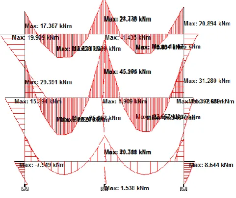
2.1 RESULTS
The maximum bending moment is 252.16 kN-m. And the maximum shear force was 764.4 kN.
Fig -3: Max Bending moment for beam
[image:2.595.41.294.54.506.2] [image:2.595.347.521.468.593.2]© 2019, IRJET | Impact Factor value: 7.211 | ISO 9001:2008 Certified Journal
| Page 4143
Fig -5: Max Bending moment for Column
Fig -6: Max shear force for column
The reactions of the structure are shown below. Based on these reactions isolated footings are provided.The design of footing is done by grouping method; the max reaction was taken as 1100kN.
Fig -7: Reactions for footing
2.2 COST ESTIMATION
Table -3: ABSTRACT OF ESTIMATION
The total amount estimated only for structural work, flooring work, painting, water tanks were excluded.
3. STEEL STRUCTURE
[image:3.595.75.248.92.255.2]The analysis and design of steel structure is carried out on Stad.pro v8i. The center line drawing is imported in Stad.pro from AutoCAD for analysis under different loads like Dead loads, live loads and various load combinations. The wind load is not considered as the structure is only 2 storey. The sizes of slab, columns and beams are mentioned in the table below.
Table -4: Structural elements with properties
Steel Structures Properties
Sections Size (mm)
Column ISHB 350
ISHB 300
Beam
ISMB 300
ISMB 350
ISMB 400
ISMB 500
Slab Plates 50mm thick
[image:3.595.320.550.269.404.2]The sizes of the structural elements will be based on the loads acting on it. The below table shows the load calculated.
Table -5: LOADS CALCULATED
Loads plinth Ground floor First floor
Wall load kN/m 13.4 13.4 kN/m -
Self-weight of
slab - 0.934 kN/m2 0.934 kN/m2
Floor finish 0.75kN/m2 (if required )
Live load
(library) - 6 kN/m2 2 kN/m2
Live load
(other rooms) - 4 kN/m2 2 kN/m2
Passage wall
load kN/m 3.68 3.68 kN/m -
Stair case 8 kN/m 8 kN/m 4 kN/m
The load combinations used are: 1.5(DL+LL)
[image:3.595.70.252.288.441.2] [image:3.595.43.564.446.797.2] [image:3.595.42.278.540.593.2]© 2019, IRJET | Impact Factor value: 7.211 | ISO 9001:2008 Certified Journal
| Page 4144
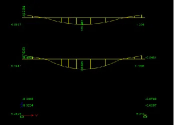
3.1 RESULTS
The maximum bending moment is 277.358 kN-m. And the maximum shear force was 235 kN.
Fig -8: Max Bending moment
Fig -9: Max shear force
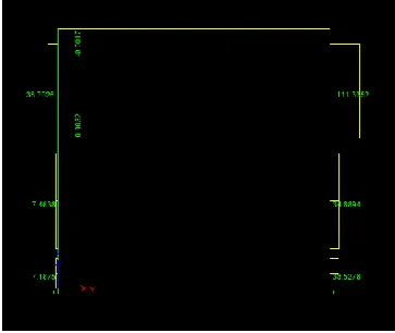
Fig -10: Reactions for footing
The reactions of the structure are shown below. Based on these reactions footing is provided with strong Rcc pedestrial. The max reaction was taken as 800kN.
[image:4.595.48.556.83.738.2]3.2 COST ESTIMATION
Table -6: ABSTRACT OF ESTIMATION
4. COMPARISON AND CONCLUSION
4.1 COMPARISION
[image:4.595.45.286.154.356.2]© 2019, IRJET | Impact Factor value: 7.211 | ISO 9001:2008 Certified Journal
| Page 4145
Chart -2: Comparison of max shear force
Chart -3:Comparison ofCost estimation
Chart -4:Comparison of Reactions
4.2 CONCLUSION
From the above it is concluded that steel structure is more suitable as compared to other structure up to 2 story. A building constructed using steel structures has less construction cost as determined in this work. The dead load on the steel structure is less compared to concrete structure. In steel structure we found more bending moment but less shear force compared to Rcc structure. The size of the steel structure elements is small. The standard steel sections are readily available so that the construction speed is higher and they may be kept ready by the time the site is ready and the structure erected as soon as the site is ready. Hence there is lot of saving in construction time. As the time is saved the construction cost will reduce.
REFERENCES
[1] Mohammed Ayyad, “Analysis of Conventional Industrial
Steel Building Under Lateral and Crane Loads,” IJRTER, vol. 4, April. 2018, pp. 562-567, [ISSN: 2455-1457].
[2] N.Krishna Raju, “Advanced Reinforced concrete design”,
CBS publishers & distributors, Delhi.
[3] D. R. Panchal and P. M. Marathe, “Comparative Study of
R.C.C., Steel and Composite (G+30) storey building”, Institute of Technology, Nirma University, Ahmedabad – 382 481, pp- 1-6, December, 2011.
[4] IS:456-2000 “Indian Standard code of practice for plain
and reinforced Cement Concrete”, Bureau of Indian Standards, New Delhi.
[5] SP:16-1980 “Design aids Reinforced Concrete” to
IS:456-1978, Bureau of Indian Standards, New Delhi
[6] IS: 800-2007" Code of practice for general construction
in steel, Bureau of Indian Standards", New Delhi.
BIOGRAPHIES
Mohammed Ayyad Assistant professor
Department of Civil Engineering AITM, Bhaktal,
Karnataka, India
Roopak Naik
Department of Civil Engineering AITM, Bhaktal,
Karnataka, India
J.Tejan
Department of Civil Engineering AITM, Bhaktal,
Karnataka, India
Bharati Naik
Department of Civil Engineering AITM, Bhaktal,
Karnataka, India
Sudeep Acharya
Department of Civil Engineering AITM, Bhaktal,
Karnataka, India