© 2019, IRJET | Impact Factor value: 7.211 | ISO 9001:2008 Certified Journal | Page 5826
Design & Implementation of Sensorless BLDC Motor Drive with Digital
Filters for BEMF using dsPIC33CK Microcontroller
Sachith D’Souza
1, Rudranna Nandihalli
21
PG Student, Dept. of Electrical and Electronics Engineering, R V College of Engineering, Bengaluru, India
2Dept. of Electrical and Electronics Engineering, R V College of Engineering, Bengaluru, India
---***---Abstract -
The permanent magnet brushless DC motor(PMBLDC) is a high-power density and robust electric motor. These motors are being used due to high efficiency of motor drive and low noise operation. However due to the commutation sequence that is necessary to spin the motor freely requires position encoders and hall sensors that add to the size and cost of controller. In sensorless control, the stator back-EMFs (BEMF) are being estimated and the required commutation sequence is generated. The BEMF is being estimated using the analog comparators, op-amps, low pass filters that not only add to the cost but increases the size and space of controller. In this paper a sensorless BLDC drive is being implemented using dsPIC33CK microcontroller operating at 100MHz, that digitally filters the BEMF noise to obtain the rotor position and generate precise PWM commutation sequence to spin the motor. These controllers not only decrease the cost and space; it also reduces the BEMF noise and reduces the cogging torque on rotor. Thus, a BLDC motor that runs smoothly with less audible noise is obtained.
Key Words: Sensorless BLDC, BEMF, Digital Filter,
Microcontroller, dsPIC, Torque, Speed.
1. INTRODUCTION
The permanent magnet brushless DC (PMBLDC) motor is increasingly being used in computers, aerospace, military, automotive, industrial and household products because of its high-power density, high torque, compactness, and high efficiency. Moreover, these drives are gaining more momentum due to their silent and maintenance free operation. The BLDC motor is inherently electronically controlled and requires rotor position information for proper commutation of stator field. The BLDC motor is commutated every 60° electrical, with trapezoidal back-EMFs (BEMF) and six commutation points are obtained to drive a BLDC motor. Usually, in order to detect the current commutation points, position sensors such as hall sensors are widely used in BLDC motor control systems. An optical encoder is often adopted to measure the rotor speed for speed controlling. These hall sensors and optical encoders not only increase the cost but also make the BLDC motor control system less reliable [1-3]. Thus, sensorless technology is preferable solution than sensor control. The review is being conducted on the control strategy and technique, type of components used and the performance of the controller to run the BLDC motor. Many researchers
around the globe have designed many sensorless control strategies. These technologies have been implemented using analog comparator, op-amps [4-7] and also with low pass filters [8-11]. The sensorless control with vector positioning, phase advancing, reduced number of switches, PID control and power factor correction have been discussed [12-18]. The implementation using digital filters can improve the drive performance. One such controller with digital filtering is being implemented using the Majority Detection Filter.
1.1
Objectives & Scope
The objectives are
Simulation of sensorless BLDC motor control using the back-EMF sensing & with digital filters
Implement Majority Function Filter, Look up Table of True-False Events
Hardware implementation using dsPIC33CK with digital filters, & PWM control program to spin the BLDC motor The scope of the work is to obtain a sensorless BLDC motor controller that generates the required commutation sequence with minimal use of analog components and ICs, thereby minimize the size and the cost of the controller and obtain high efficiency and reliable BLDC drive.
2. BLDC MOTOR THEORY & CONTROL
The BLDC motor is a non-salient type surface magnet rotor that induces three phase trapezoidal voltages. The absence of the brushes and commutator makes it more efficient and reliable. The motors are commutated electronically using a 3-phase inverter bridge. The commutation is split into 6 sectors for 120⁰ conduction [19]. The circuit diagram is as shown in Fig –1. The terminal voltage is being sensed at the motor terminals and the microcontroller filters the noise and decides the commutation sequence based on the BEMF signals. The commutation table along with the BEMF phase selected is as mentioned in Table -1.
© 2019, IRJET | Impact Factor value: 7.211 | ISO 9001:2008 Certified Journal | Page 5827
Fig -1: Sensorless BLDC motor controlTable -1: Commutation Table
Sector A B C Phase for BEMF Detection
1 H 0 L B
2 H L 0 C
3 0 L H A
4 L 0 H B
5 L H 0 C
6 0 H L A
Fig -2: Excitation Circuit for 6 step operation
Fig -3: Motor Terminal voltage waveforms
The equivalent circuit of the BLDC motor is obtained by considering the resistance, reactance and the BEMF component on each phase [20]. The same is as shown in Fig -4. The modelling of the circuit helps in obtaining the voltage, power and torque equations as mentioned below.
Where, Va is the terminal voltage per phase, ia, is the current per phase, ea is the BEMF voltage per phase, Rs is the stator resistance per phase, L is the equivalent self-inductance per phase, M is the mutual-inductance between phases & ρ is the laplace operator (motor constant).
Fig -4: Equivalent Circuit of BLDC Motor The BEMF is estimated by the equation
where B is magnetic field intensity, l is mean length, N is speed in rpm, r is radius and ωm is the angular velocity. The torque is obtained by
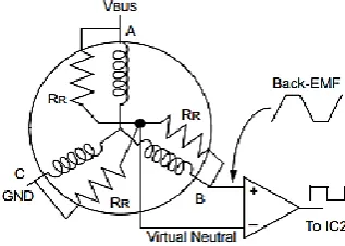
The virtual neutral voltage reconstruction is necessary to find the zero crossings. This is essential for star and delta windings as it saves the motor cost and the hardware cost. The equivalent circuit of the same is as shown in Fig -5.
Fig -5: BEMF comparison with the terminal voltage The virtual neutral voltage (Vn) can be reconstructed by
[image:2.595.43.278.272.520.2] [image:2.595.354.513.521.634.2] [image:2.595.81.246.548.687.2]© 2019, IRJET | Impact Factor value: 7.211 | ISO 9001:2008 Certified Journal | Page 5828
3. BLOCK DIAGRAM & FLOWCHART
The block diagram is as shown in Fig – 6 and the functionality of the blocks are as follows. The DC power supply is fed to the development board the onboard voltage regulator supplies the required voltages to the components, the PWM buffer controller and gate driver circuit provide the required gate pulse signals to control the MOSFETs mounted on the board.
Fig -6: Block Diagram of Module
The block diagram of the operations that are performed on the microcontroller is as shown in Fig -7. The PWM switching is 20kHz and the clock frequency of microcontroller operation is 100MHz.
Fig -7: Software Control Block Diagram
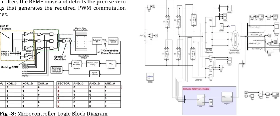
[image:3.595.314.554.174.447.2]The digitalization and computation of signals is briefly described, the block diagram is as shown in Fig -8. The BEMF signals are active masked, the lookup table of Majority Function filters the BEMF noise and detects the precise zero crossings that generates the required PWM commutation sequences.
Fig -8: Microcontroller Logic Block Diagram
The flowchart of the program is as shown in Fig -9, the switch buttons are used to obtain the START/STOP operation as well the direction of rotation. The potentiometer is being used to achieve the speed control. The minimum speed is 1000rpm @ 85Hz and maximum speed is 3300rpm @ 275Hz.
[image:3.595.51.274.188.317.2]Fig -9: Flowchart of the program
4. DESIGN & SIMULATION
[image:3.595.39.290.393.506.2]
The simulation model using MATLAB-SIMULINK is as shown in Fig -10. The BLDC motor specifications & ratings are as mentioned in Table -2.
[image:3.595.68.555.554.757.2]© 2019, IRJET | Impact Factor value: 7.211 | ISO 9001:2008 Certified Journal | Page 5829
Table -2: Motor SpecificationsPARAMETER VALUES
Voltage, Current, Power 24V, 1A, 36W
Number of poles, pole pairs 10, 5
Max Rated Speed 3300rpm
Max Torque 200m N-m
Insulation Type Class B
The simulation waveforms that are obtained are as shown in Fig -11 for the three-phase line to line voltages. Fig -12 for the stator BEMF on each phase with the virtual neutral voltage. The torque and speed are as shown in Fig -13. The reading obtained are tabulated in Table -3.
Fig -11: Line to Line motor terminal voltages
Fig -12: Stator BEMF with respect to virtual neutral point
Fig -13: Speed and Torque waveforms
Table -3: Simulation Results
Duty
Cycle Frequency
(Hz)
Curre nt Draw
n (A)
Phase Curren t (A)
Line to Line Voltage
(V)
Speed (rpm)
0.65 85 0.4 0.38 14.15 1018
0.85 180 0.6 0.53 17.68 2160
0.99 275 0.63 0.58 18.23 3320
5. HARDWARE IMPLEMENTATION
The hardware implementation of the circuit is as shown in Fig -14. The DC current drawn, stator current, motor terminal voltages are noted down along with the speed and frequency.
Fig -14: Line to Line motor terminal voltages The PWM waveforms of 6 switches for clockwise rotation and anti-clockwise rotation are as shown in Fig -15 & Fig -16 respectively. The pole voltage with respect to ground & the line to line voltage with stator phase current are as shown in Fig -17 & Fig -18 respectively.
Fig -15: PWM waveforms for clockwise rotation
© 2019, IRJET | Impact Factor value: 7.211 | ISO 9001:2008 Certified Journal | Page 5830
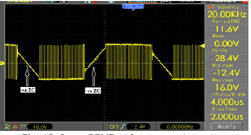
Fig -17: Pole voltage & stator current waveform [image:5.595.40.285.250.383.2]Fig -18: Line to line voltage & stator current waveform The zero crossing of BEMF on each phase with the PWM switching of 20kHz is as shown in Fig -19. The low-speed and high-speed readings of motor are obtained using a non-contact type tachometer as shown in Fig -20.
Fig -19: Stator BEMF with zero crossing points
Fig -20: Low speed (L) & High Speed (R) readings
The no load readings obtained are tabulated in Table -4. The load test at constant speed operation with variable torque are as shown in Table -5 for 1500rpm and Table -6 for 2000rpm respectively.
[image:5.595.313.553.412.482.2]Table -4: No load readings
Table -5: Load test readings @ 1500rpm
Table -6: Load test readings @ 2000rpm
The following observations are made during the test The speed is directly proportional to the frequency
and is same as theoretical value calculated for both direction of rotations.
The motor shaft runs freely with less torque pulsations and less noise.
6. CONCLUSION
The hardware implementation results show that it is more essential to filter the BEMF by digital filters than analog filters. The digital filters reduce the analog components, have faster computation speed and they are being implemented in digital signal processor (DSP) that is being used to generate the PWM signals. Hence, by implementing DSP based sensorless speed control of BLDC and by digital filtering the back-EMF signals the size of hardware and the cost of the controller are extensively reduced.
ACKNOWLEDGEMENT
[image:5.595.40.285.453.585.2] [image:5.595.61.264.610.697.2]© 2019, IRJET | Impact Factor value: 7.211 | ISO 9001:2008 Certified Journal | Page 5831
inputs on power electronic converters and industrial drives.I deeply extend my gratitude to my parents for their constant support, guidance and encouragement in all my activities.
REFERENCES
[1] A.Saxena, "Performance and cost comparison of PM BLDC motors for ceiling fan," 2014 IEEE International Conference on Power Electronics, Drives & Energy Systems (PEDES), Mumbai, pp. 1-5, 2014.
[2] C. Xia and X. Li, "Z-Source Inverter-Based Approach to the Zero-Crossing Point Detection of Back EMF for Sensorless Brushless DC Motor," in IEEE Transactions on Power Electronics, vol. 30, no. 3, pp. 1488-1498, March 2015.
[3] Microchip Technology Datasheet -
dsPIC33CK256MP508 16-bit Motor Control applications
[4] Baisong Li, Ruixia Ma, Fengchao Fu, Xinhai Jin and Wei Chen, "A new sensorless control method for brushless permanent magnet DC motors," 2013 IEEE
International Symposium on Sensorless Control for Electrical Drives and Predictive Control of Electrical Drives and Power Electronics (SLED/PRECEDE), Munich, pp. 1-7, 2013.
[5] Yushui Huang, Yugang Xin and Weicheng Zhang, "An improved BEMF detection method for sensorless BLDC motors," 2008 IEEE International Conference on Industrial Technology, Chengdu, pp. 1-4, 2008. [6] J. Shao, "An Improved Microcontroller-Based
Sensorless Brushless DC (BLDC) Motor Drive for Automotive Applications," in IEEE Transactions on Industry Applications, vol. 42, no. 5, pp. 1216-1221, Sept.-Oct. 2006.
[7] K. T. Ajmal and M. T. R. Pillai, "Back EMF based sensorless BLDC drive using filtered line voltage difference," 2014 Annual International Conference on Emerging Research Areas: Magnetics, Machines and Drives (AICERA/iCMMD), Kottayam, pp. 1-6, 2014. [8] D. Kim, K. Lee and B. Kwon, "Commutation Torque Ripple Reduction in a Position Sensorless Brushless DC Motor Drive," in IEEE Transactions on Power Electronics, vol. 21, no. 6, pp. 1762-1768, Nov. 2006. [9] C. D. Bhagat, S. P. Nikam and B. G. Fernandes, "Design
and development of sensorless controller for DC-operated mixer-grinder," 2016 First International Conference on Sustainable Green Buildings and Communities (SGBC), Chennai, pp. 1-6, 2016. [10] X. Zhou, X. Chen, C. Peng and Y. Zhou, "High
Performance Nonsalient Sensorless BLDC Motor Control Strategy from Standstill to High Speed," in IEEE Transactions on Industrial Informatics, vol. 14, no. 10, pp. 4365-375, Oct. 2018.
[11] K. Kroics, J. Zakis and U. Sirmelis, "Implementation of the back EMF zero crossing detection for BLDC motor," 2017 IEEE 58th International Scientific Conference on Power and Electrical Engineering of Riga Technical University (RTUCON), Riga, pp. 1-4, 2017.
[12] M. F. Mohammed and D. Ishak, "Improved BLDC motor performance with digitally filtering back-EMF using dsPIC30F microcontroller," 2009 IEEE Student
Conference on Research and Development (SCOReD), Serdang, pp. 491-494, 2009.
[13] Y. Chen, S. Huang, S. Wan and F. Wu, "Dynamic equations algorithm of the sensorless BLDC motor drive control with Back-EMF filtering based on dsPIC30F2010," Proceedings of the 30th Chinese Control Conference, Yantai, pp. 3626-3630, 2011. [14] Nagadeven, Soib Taib, K S Rama Rao, “DSP
BasedSensorless Control of a BLDC Motor with Direct Back EMF Detection Method”, International
Conference on Control, Instrumentation and Mechatronics Engineering (CIM’07), Johor Bahru, Malaysia, May28-29, 2007
[15] A. Ulasyar, H. Sheh Zad and A. Zohaib, "Intelligent Speed Controller Design for Brushless DC Motor," 2018 International Conference on Frontiers of Information Technology, Islamabad, Pakistan, pp.19-23, 2018
[16] Y. Lai and Y. Lin, "Novel Back-EMF Detection Technique of Brushless DC Motor Drives for Wide Range Control Without Using Current and Position Sensors," in IEEE Transactions on Power Electronics, vol. 23, no. 2, pp. 934-940, March 2008.
[17] V. Bist and B. Singh, "Power factor correction in sensorless BLDC motor drive," 2014 IEEE 6th India International Conference on Power Electronics (IICPE), Kurukshetra, pp. 1-6, 2014.
[18] C. Ta, "Pseudo-vector control - An alternative approach for brushless DC motor drives," 2011 IEEE International Electric Machines & Drives Conference (IEMDC), Niagara Falls, ON, pp. 1534-1539, 2011. [19] Bimal K. Bose, "Modern Power Electronics and AC
Drives”, Second Impression 2017, Prentice Hall PTR, 2002
[20] R Krishnan, "Electric Motor Drives: Modeling, Analysis, and Control”, 2nd Edition by Pearson Publications, 2001
BIOGRAPHIES
Dr. Rudranna Nandihalli, Professor & HOD of EEE Dept, RVCE has 29 years of teaching experience. He has published over 15 research and technical papers. His current research interests include Power Electronics, Power Systems, HV Eng. & Control Systems.