© 2019, IRJET | Impact Factor value: 7.211 | ISO 9001:2008 Certified Journal | Page 1463
Simulation of Turning Process using Explicit Dynamics
Gudala Sandeep Kumar
1, Dr. Resapu Rajeswara Reddy
21
Post Graduate Student, Department of Mechanical Engineering, Gitam University, Visakhapatnam,
Andhra Pradesh, India.
2
Assistant Professor, Department of Mechanical Engineering, Gitam University, Visakhapatnam,
Andhra Pradesh, India.
---***---Abstract - Chip formation is one of the primary
characteristics in the machining of ductile materials. Modelling of metal cutting is performed using different tools in turning process. Simulation of chip formation process is performed by using a Tungsten and steel-4340 tools where Aluminium-1100 is used as work piece. ANSYS explicit dynamics is used to simulate metal cutting for a turning process under dry cutting conditions. The effect of different velocities and depth of cuts (DOC) are studied. This paper discusses in detail the working of simulation in ANSYS workbench and also presented the results obtained for shear stress and equivalent plastic strain at various depth of cuts and velocities when the tool is in flexible conditions.
Key Words: Ductile, Modelling, Simulation Tungsten,
Depth of cut, Ansys, Flexible.
1. INTRODUCTION
As metal cutting is mainly a chip formation process, one of the most important considerations when modeling is the approach by which elements of the work piece material separate as the cutter advances. Metal components are made into different shapes and dimensions by using various metal working processes. Metal working processes are classified into two major groups. One is non-cutting shaping or metal forming process where no chip formation takes place and metal is shaped under action of heat, pressure or both. Example: forging, rolling, pressing, etc. and the other is Cutting shaping or metal cutting or chip forming process where the components are brought to desired shape and size by removing the unwanted material from the parent metal in the form of chip through machining. Example: turning, drilling, milling, etc. Additionally some environment called cutting fluid is generally used to ease machining by cooling and lubrication.
Machining is an essential process of finishing by which work pieces are produced to the desired dimensions and surface finish by gradually removing the excess material.
Metal components are made into different shapes and dimensions by using various metal working processes.
Turing is one of the basic machining processes. It is used to remove the work piece material with the help of the cutting tool.
Fig 1: metal cutting
2. ANSYS EXPLICIT DYNAMICS
ANSYS explicit dynamics engineering simulation solutions are ideal for simulating physical events that occur in a short period of time and may result in material damage or failure. ANSYS Explicit STR, like ANSYS Mechanical, simulates the response of structures to loadings. Explicit STR extends the capabilities of Mechanical to problems involving short-duration severe loading, large material deformation and material failure. The explicit solution method can handle geometries with complex non-linear contact that may cause difficulty with the implicit solver in ANSYS Mechanical. It is an analysis system integrated within ANSYS Workbench, using the same familiar graphical user interface (GUI) as ANSYS Mechanical and other integrated analysis systems. If you already use ANSYS Mechanical, shifting to Explicit STR is fairly quick, so you can produce results without a lot of learning effort. Explicit STR easily handles the response of materials from impacts, high pressures, and other forms of loading that result in deformation, failure and fragmentation. Companies in aerospace, automotive, electronics, manufacturing, consumer products and other industries use Explicit STR to improve their designs through simulation.
The solution method used by ANSYS Explicit STR software is based on the robust and time-tested Lagrange solver of the ANSYS AUTODYN analysis program.
© 2019, IRJET | Impact Factor value: 7.211 | ISO 9001:2008 Certified Journal | Page 1464
3. DESIGN AND MODELLING
The basic tool parameters are taken for modelling tool geometry as the first step.
The tool geometry models are then modelled using CATIA and ANSYS Design Modeller. After modeling, the tool geometries are saved and imported into ANSYS for simulation.
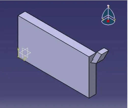
[image:2.595.309.577.84.257.2]The design and model of tool1 (Tungsten) and tool2 (steel4340) and work piece (Alumimium-1100) is as shown below
Fig 2: Designed in catia
Fig 3: Designed in Ansys
[image:2.595.38.299.243.462.2]The tools which are designed in catia are drawn with
rake angle, back rake angle, relief angle, tool nose
radius, tool length and also for work piece.
[image:2.595.314.572.290.454.2]Fig 4: Imported geometry from catia
Fig 5: Meshing for work piece and tungsten tool
Fig 6: Meshing for work piece and steel4340 tool
Meshing is made for the tool and work piece by
assigning element size or by default meshing size
.
4. SIMULATION RESULTS
[image:2.595.312.560.493.654.2] [image:2.595.35.294.498.664.2]© 2019, IRJET | Impact Factor value: 7.211 | ISO 9001:2008 Certified Journal | Page 1465
where the only work piece material used isAluminium-1100.The results obtained in ANSYS simulation for depth of cut of 1mm and 2mm for tool in flexible condition are evaluated. Results for shear stress and equivalent stress are evaluated.
The table shows the variation between two different depths of cut at various velocities. Equivalent plastic strain at 1mm and 2mm depth of cuts at 20m/s, 40m/s, and 70m/s are taken from simulations.
TOOL 1 –TUNGSTEN
WORKPIECE-ALUMININUM-1100
[image:3.595.329.544.84.270.2]Tab-1: Equivalent plastic strain at 1mm&2mm DOC
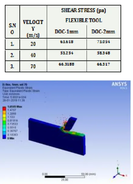
Fig 7: Equivalent plastic strain at 70m/s & DOC 1mm
[image:3.595.329.545.306.495.2]Fig 8: Equivalent plastic strain at 70m/s & DOC 2mm
[image:3.595.57.276.424.727.2]Fig 9: shear stress at 70m/s & DOC 1mm
Fig 10: shear stress at 70m/s & DOC 2mm S.NO
VELOCITY (m/s)
EQUIVALENT PLASTIC STRAIN
DOC-1mm DOC-2mm
1. 20 1.251 1.3046
2. 40 1.4138 1.6135
3. 70 1.6545 1.7657
[image:3.595.329.542.533.724.2]© 2019, IRJET | Impact Factor value: 7.211 | ISO 9001:2008 Certified Journal | Page 1466
TOOL 2 –STEEL4340WORKPIECE-ALUMININUM-1100
Tab-3: Equivalent plastic strain at 1mm&2mm DOC
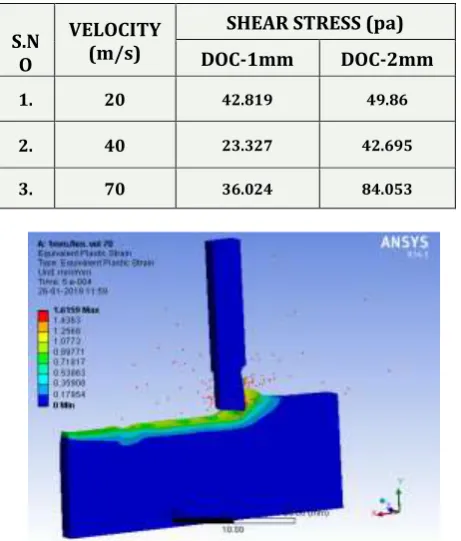
[image:4.595.332.552.84.271.2]Tab-4: Shear stress at 1mm&2mm DOC
[image:4.595.333.549.308.495.2]Fig 11: Equivalent plastic strain at 70m/s & DOC 1mm
Fig 12: Equivalent plastic strain at 70m/s & DOC 2mm
Fig 13: shear stress at 70m/s & DOC 1mm
Fig 14: shear stress at 70m/s & DOC 2mm
The simulation values which are obtained are plotted, on graphs to know the difference for various depth of cut (DOC) and various velocities.
Graph-1 S.N
O
VELOCIT Y (m/s)
EQUIVALENT PLASTIC STRAIN
DOC-1mm DOC-2mm
1. 20 1.4021 1.9103
2. 40 1.689 2.6862
3. 70 1.6159 1.7697
S.N O
VELOCITY (m/s)
SHEAR STRESS (pa)
DOC-1mm DOC-2mm
1. 20 42.819 49.86
2. 40 23.327 42.695
[image:4.595.44.275.320.591.2] [image:4.595.72.271.622.757.2]© 2019, IRJET | Impact Factor value: 7.211 | ISO 9001:2008 Certified Journal | Page 1467
Graph-2Graph-3
Graph-4
Graph 1 & 2 shows the equivalent plastic strain at various velocities (20, 40 & 70m/s) at 1mm and 2mm depth of cut.
Graph 3 & 4 shows shear stress at various velocities (20, 40 & 70m/s) at 1mm and 2mm depth of cut.
CONCLUSION
All the results are obtained from simulation performed in Ansys explicit dynamics. The results of simulation are shown in figures and also tabulated for various velocities and tool conditions. We observe that equivalent plastic strain increases with increase in depth of cut and increase
in velocities. In the same way the shear stress also increases with increase in depth of cut and velocities.
REFERENCES
1. Maheshwari N Patil, Shreepad Sarange “Finite Element Analysis of Von Mises Stresses & Deformation at Tip of Cutting Tool”, (IJIRAE) Volume 1 Issue 1 (April 2014).
2. T. Ozel, D. Ulutan “Prediction of machining induced residual stresses in turning of titanium and nickel based alloys with experiments and finite element simulations”, CIRP Annals - Manufacturing Technology 61 (2012) 547–550.
3. J. Zouhar, M. Piska “Modelling the orthogonal machining process using cutting tools with different geometry”, Mechanical Engineering, Brno, Czech Republic.
4. Shravankumar C, Bharat.S.Kodli “A Finite Element Analysis of Orthogonal Machining Using Different Tool Edge Geometries and End Relief Angles”, (IJERT) Vol. 2 Issue 10, October – 2013, ISSN: 2278-0181
BIOGRAPHIES
Sri. Gudala Sandeep Kumar
Post Graduate student, Department of Mechanical Engineering, Gitam University, Visakhapatnam, Andhra Pradesh, India.
Dr. Resapu Rajeswara Reddy