Dynamic Stability Analysis of Periodically Time-Varying
Rotor System with a Transverse Crack
Costin D. Untaroiu1, Alexandrina Untaroiu1, Mihail Boiangiu2
1Rotating Machinery and Controls (ROMAC) Laboratories, Department of Mechanical and
Aerospace Engineering, University of Virginia, Charlottesville, USA
2Chair of Mechanics, “Politehnica” University, Bucharest, Romania
E-mail: [email protected]
Received January 19, 2011; revised June 30, 2011; accepted July 7, 2011
Abstract
Fatigue cracks may appear in horizontal rotating machinery due to periodic stresses imposed to its shaft. The investigation of stability behavior of cracked rotors can lead to proper diagnosis of machinery and to prevent possible accidents caused by the rotor failure. In this study, the dynamic stability of a rotor with a transverse crack is investigated. Models of both open and breathing cracks are developed and then used in the model of a cracked Jeffcot (de Laval) rotor. The stability of rotor motion equations represented by differential equa-tions with periodic coefficients is investigated using Floquet theory. While both crack models show instabil-ity regions around the first un-damped frequency, sub-harmonic regions are predicted by the breathing crack models. Compared to perturbation methods frequently used to determine the stability regions, the transition matrix approach used in this study can be applied to complex models of rotors and consequently may help in the identification of cracks in rotating machinery.
Keywords:Rotordynamics, Cracked Rotors, Stability, Breathing Crack
1. Introduction
Rotordynamic systems, such as gas turbine and com-pressors, are extensively used in industry for many dec-ades. Even though the stability of rotordynamic systems during operation is a major design requirement, their extensive use under heavy loadings may lead to occur-rence of fatigue cracks, which can propagate and gener-ate serious accidents [1]. Therefore, the investigation of vibrational characteristics of the cracked rotors has gained significant attention during the last decades [1,2].
The presence of a crack in a rotor shaft introduces a local flexibility that affects its vibration response, and its stability [2,3]. The fatigue cracks in the shaft of rotors are usually transverse, so the model of a rotordynamic system becomes asymmetric (open crack model). In ad-dition, the crack may open and close as shaft rotates due to the rotor weight or unbalance, which leads to periodi-cally time-varying equations of motion for the system (breathing crack model).
A traditional approach to investigate the stability of rotor systems with cracks is to apply perturbation meth-ods [4] to determine approximations of stability
border-lines. This approach provides intuitive values of sub/ super-harmonic resonances of un-damped cracked rotors, but its application to complex rotor models is limited.
In this paper, the stability of a cracked rotor system at operating speeds below the first critical speed is investi-gated. The analysis uses Floquet’s theory [4,5], which involves computation of a transition matrix over a time period. The stability boundaries are determined by checking the stability of systems corresponding to points of uniform mesh within the domain of interest. The ap-proach proposed is illustrated through a numeric example of a simple Jeffcott (de Laval) rotor model and two crack models (open and breathing). Even though the current approach is more computational expensive than the per-turbation method, the advantage is that it can be applied to any rotor or structure which has one or multiple cracks.
2. Equation of Motions
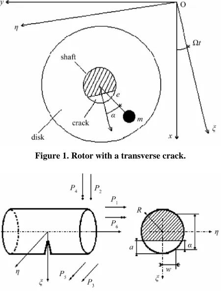
Jeffcott rotor with a disk of mass m mounted at mid-span of a massless elastic shaft is considered in this study. The coordinates x, y and ξ, η represent the stationary and ro-tating axes (Figure 1). The eccentricity of the mass cen-ter of the disc from the geometric centre of the disc is e. The rotational speed and the damping coefficient are Ω
and c, respectively.
Since the local flexibility induced by the transverse crack generates equations of motion with periodic stiff-ness coefficients in the fixed reference frame, the equa-tions of motion of Jeffcott rotor are expressed in a rotat-ing frame as follows:
2 2
2 2
2
cos cos
2
sin sin
m c k k
me mg t
m c k k
me mg t
(1)
where k, k are direct stiffnesses along ξ, η direc-tions, and k, k are cross-coupled stiffnesses. The formulas for these stiffness coefficients for a cracked rotor are derived using the theory developed in [6] by Dimarogonas and Paipetis in the following section.
3. Determination of Stiffness Coefficients of
Cracked Rotor
This study considers a general case with a shaft with radius R and a transverse crack of depth a (see Figure 2). In the cross-section of crack, the shaft is loaded with axial force P1, shear forces P2 and P3, bending moments
P4 and P5, and torsion moment P6. The transverse crack induces additional strain energy Uc calculated based on
the stain energy density function J:
0 0
d d
a a
c c
U
U J
(2)The stain energy density function J is calculated based on the theory of fracture mechanics and has the follow-ing form [7]:
2
6 2 6 2
6 21 1 1
1
1
Il IIl IIIl
l l l
J K K K
E
(3) where E is the modulus of elasticity, ν is the Poisson ratio (0.3 for steel), Kij are the crack stress intensity
fac-tors for the fracture modes (iI, II, III), and Pj are the
loads.
The additional displacement ui induced by the crack
can be calculated using Castigliano’s theorem as follows [5]:
[image:2.595.313.536.79.227.2]Figure 1. Rotor with a transverse crack.
Figure 2. A cracked shaft element in general loading.
c i
i
U u
P
(4) The local flexibility coefficient cij due to the crack per
unit depth along all directions are:
2 0
d , 1, 2, ,6
a i
ij
j i j
u
c J
P P P
i j
(5)
Assuming a transversal crack located at the middle of the shaft next to the disk, the additional deflections due to the crack along the and directions, and , are estimated applying Equation (2):
2 2
3 3
d ;
d A c
A c
J A
U
P P
J A
U
P P
(6)For a completely open crack the area integration is:
2 2 2
2 0
d a R a a R R w d d
a R a A
A w
[image:2.595.311.536.81.379.2]If the influence of the axial force and torsion moment are neglected, since it is known their influence on the additional transversal deflections is low, the stain energy density function has the following form:
2
2 2 2
4 5 3 2
1
1
I I II III
J K K K K
E
(8)
The stress intensity factors [7] from the above expres-sion are:
5 2
5 4 2 4 2
3 4
4 4 1 4 1
3 2
3 2 2 2
2 π 2 π
4 π π 4 4 π π 4 π π
π ; π
π π
I I
II II III III
P h P L h
K aF a h aF a h
R R
P L P
K w aF a h w aF a h
R R
kP kP
K F h K F h
R R
(9)
Here k6 1
7 6
is a shape coefficient for circular cross section, h R2w2 and:
3 1 4 2 2 30.752 2.02 0.37 1 sin cos
0.923 0.199 1 sin cos
1.122 0.561 0.085 0.18 1
where π 2
II III h tg F h tg F h
h h h
F h
h tg
F h h
(10)
The total deflections and are obtained by summing the initial deflections (without crack) and the additional
deflections induced by the crack calculated by replacing expressions (8)-(11) into Equations (6).
3 3
3 2
2 2 3 32; 2 23 3 3
48 48
L P
L P P f P f P f P f
EI EI
(11) where
3 2 2 2 2
2 2
2 8 2 4
3 2 2 2 2
2 2
3 8 1 4
2 2
23 32 8 1 2
1 2 d
48 2π π
1 2 2 d
48 π π
1 d π III A II A A
L L h k
f F h F h A
EI E R R
L L w k
f F h F h A
EI E R R
L hw
f f F h F h A
E R
(12) 2
P and P3 are obtained from the system of equations (11) as follows:
3 23
2 2
2 3 23
f f
P
f f f
;
2 23
3 2
2 3 23
f f
P
f f f
(13)
However:
2 ; 3
P kk P kk (14) Thus, the stiffness coefficients are obtained from Equations (13) and (14):
3 2 23
2 2 2
2 3 23 2 3 23 2 3 23
; ;
f f f
k k k k
f f f f f f f f f
(15)
In the case of a completely open crack due to symme-try f230, so the stiffness coefficients are:
2 3
1 1
; ; 0
k k k k
f f
(16) Introducing the following parameters:
2 2 2
0 3 0 48 ; ; ; ; 2 k k
k EI c
k
m L m m m
(17)
The homogeneous systems of equations in the case of an open crack are:
where
0 0 2 2 0 2 2 0 2 2 1 0 ; ; 2 2 0 1 2 ; 2 M C K (19)During the shaft rotation, the axial loads in the section of the crack may change continuously due to the rotor self-weight and unbalance. When the cracked section is under compressive load the shaft behaves as if has no crack, and when it is under traction load the crack opens. Due to these fluctuations, the crack is said to be breathing and in the equations of motion appear time-dependent coefficients.
The stiffness coefficients were calculated by Jun et al.
[8] using a complex method in which a partially open/close crack is assumed. However, the stiffness co-efficients showed an almost similar variation like “clas-sic” model, which assumes that the sign of ξindicates full crack opening and closing. For simplicity, in this study, the “classic” model is employed, so the stiffness matrix for a breathing crack model has the following form:
0, 22,
K t T
K t
K t T T
where T 2π (20)
2 2 0 2 2 0 2 2 0 0 2 2 0 0 2 ; 2 2 2 K K (21)4. Stability Analysis Using the Floquet
Theory
To apply Floquet theory, the second-order equations of motion (Equation (18)) is reduced to a first-order differ-ential system [9]:
0 0
0 0 0
M X C K t X
M X M X
(22)
or
Y A t
Y
tY X X where
1 1
0
M C M K t
A t I
(23)
Based on Floquet theory [5], the solution of Equation (23) has the following form:
p tk
k
Y t B t C e (24) where
Y t
and
p tk
k
C e are 4 × 1 column matrices, and B t
is a 4 × 4 square matrix with period2π
T . Replacing t0,T into the Equation (24)
Y 0
B
0
Ck (25)
0
, 1, 2k k
p T p T
k k
Y T B T C e B C e
k
(26)
Thus, the solution of Equation (24) can be expressed as:
1 2
1
2
00 0 t
k k
Y t Q t Y
Y Y y y
(27)
where Q t
is the fundamental matrix of system (23) and has following property Q
0I4.
ki Y t
is a solution of system (23) with following
property Yki
0 kiIntroducing t T in Equation (27) result:
Y T
Q T
Y
0
(28) The square matrix Q t
is called the “transition matrix” or the “monodromy matrix”. From Equations (25)-(28) one can obtain
11 2
1 2
1 1
0 0
0 p T
Q T B C B C
B C e
(29)
where the column vector
B
0
i is the i-th column of matrix B
0 . SinceC
k are independent:
0
p Tk
0
k k
Q T B e B
(30)
where p Tk
k e
are the eigenvalues of the Q T
matrix.
k k k
p i (31) The system (22) is unstable if there is an eigenvalue which has the real part k 0 (or k 1), otherwise the system is stable. For a certain system, the columns of transition matrix can be obtained using a numerical inte-gration method and then its eigenvalues are derived to check the stability of the system.
5. A Numerical Example
0
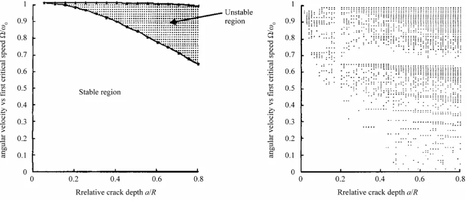
is the first critical speed of the un-cracked rotor). The stability of each point of the mesh was checked us-ing a program developed in MatLab code. In this code, the transition matrix is calculated using a Runge-Kutta integration method, and then its eigenvalues are derived to check the stability of the cracked rotor. In the case of an unstable point, the point was marked with a dot on the figure, so the dotted zones represent the instability re-gions for a cracked rotor. To see the effect of external damping on the stability of cracked rotor, in addition to undamped case (Figure 3), two damped cases (γ = 0.015, 0.03) are investigated as well (Figures 4 and 5).
Obviously, substantial differences between the two crack models are observed. The rotor with an open crack model behaves like an asymmetric rotor [10,11]. The system has an instability region around 01 ( Fig-ure 3(a)) between the natural frequencies measured along the directions of principal axes. As can be seen, the instability of the system increases significantly when the crack depth increases. When external damping is added to the system (Figure 4(a)) and then increased (Figure 5(a)), the instability region disappears at low crack depth and is slightly reduced at high crack depths.
The model of a rotor with a breathing crack predicts
[image:5.595.64.538.238.447.2](a) (b)
Figure 3. Stability of the cracked rotor: un-damped case (γ = 0) (a) open crack (b) breathing crack.
[image:5.595.68.535.481.699.2](a) (b)
(a) (b)
Figure 5. Stability of the cracked rotor: damped case (γ= 0.03) (a) open crack (b) breathing crack.
more complex instability regions (Figure 3(b)). In the case of an un-damped cracked model, large number of instability regions starts from the regions corresponding to small crack depths and then expands into the regions corresponding to larger crack depths. Compared to the open crack un-damped model, instability regions can be observed even for the regions corresponding to small rotating speeds and relatively large crack depths. As can be observed, adding external damping to the system im-proves considerably the stability of the rotor (Figure 4(b)). In addition to the instability region around 0 1 which seems slightly reduced than that of open crack model, several sub-harmonic instability regions (Figure 4(b)) are observed around 0 , ,2 2
4 3
[12]. As external damping increases, sub-harmonic instability re- gions disappear and the harmonic and the first sub-har-monic instability regions move toward the regions cor-responding to larger crack depths (Figure 5(b)). In addi-tion to the harmonic and sub-harmonic instability regions, it should be mention that the cracked rotors have also a super-harmonic instability region (around 02) [12], which for simplicity has not been analyzed in this study.
Compared to the perturbation methods [4] usually em-ployed to determine the instability regions of a cracked rotor (e.g. straightforward expansion, Lindstedt-Poicare method, the method of multiple scales, etc.), the transi-tion matrix approach used in study avoids any simplifi-cation in the equations of motion of the cracked rotor. Therefore, the transition method can be applied not only on simplified rotor models (e.g. Jeffcot model) as
per-turbation methods, but also in complex rotor models. The main disadvantage of current method is the high compu-tational cost, because it requires the verification of rotor stability for each crack depth and rotational speed. However, the continuous increase of computational speed recommends it for rotor modeled by sophisticated computational methods (e.g. finite element method [13,14]). Finally, the stability diagrams developed with the cracked rotor model and pattern recognition tech-niques [15] could be used in monitoring the condition of industrial rotors [16].
6. Conclusions
In this study, the transition matrix approach was suc-cessfully applied in calculation of stability regions of a cracked rotor. The additional stiffness introduced by a transversal crack was calculated using two models: open crack and breathing crack. In addition to the instability region around the critical frequency predicted by the open crack model, several sub-harmonic instability re-gions were predicted by the breathing crack model. Adding an external damping showed a significant reduc-tion of instability regions for both crack models. Com-pared to the perturbation methods, the transition matrix approach used in study does not require any simplifica-tion of the equasimplifica-tion of mosimplifica-tion and may be applied in the future for complex rotor models.
7. References
Rotor,” Mechanical Systems and Signal Processing, Vol. 22, No. 4, 2008, pp. 805-817.
[2] J. Wauer, “On the Dynamics of Cracked Rotors: A Lit-erature Survey,” Applied Mechanical Reviews, Vol. 43, 1990, pp. 13-17.http://dx.doi.org/10.1115/1.3119157 [3] A. D. Dimarogonas, “Vibration of Cracked Structures: A
State of the Art Review,” Engineering Fracture Mechan-ics, Vol. 55, No. 5, 1996, pp. 831-857.
[4] A. H. Nayfeh and D. T. Mook, “Nonlinear Oscillations,” John Wiley & Sons, New York, 1975.
[5] J. Dugundji and J. W. Wendell, “Some Analysis Methods for Rotating Systems with Periodic Coefficients,” American Institute of Aeronautics and Astronautics Journal, Vol. 21, No. 6, 1982, pp. 890-897.
[6] A. D. Dimaragonas and S. A. Paipetis, “Rotor Dynam-ics,” Elsevier, London, 1983.
[7] H. Tada, P. C. Paris and G. R. Irwin, “The Stress Analy-sis of Cracks Handbook,” Del. Research Corporation, Hellertown, 1973.
[8] O. S. Jun, H. J. Eun, Y. Y. Earmme and C.-W. Lee, “Modeling and Vibration Analysis of a Simple Rotor with a Breathing Crack,” Journal of Sound and Vibration, Vol. 155, No. 2, 1992, pp. 273-290.
[9] C. D. Untaroiu, “Contributions on Dynamic Stability of Rotors,” PhD. Dissertation, “Politehnica” University,
Bucharest, 1999.
[10] O. S. Jun and M. S. Gadala, “Dynamic Behavior Analysis of Cracked Rotor,” Journal of Sound and Vibration, Vol. 309, No. 1-2, 2008, pp. 210-245.
[11] M. Lalanne and G. Ferraris, “Rotordynamics Prediction in Engineering,” John Wiley & Sons, New York, 1998,. [12] R. Gasch, “Dynamic Behaviour of the Laval Rotor with a
Transverse Crack,” Mechanical Systems and Signal Processing, Vol. 22, No. 4, 2008, pp. 790-804.
[13] M. He, P. E. Allaire and P. Sheth, “ComboRotor 1.0 Beta User’s Manual,” ROMAC Report No. 521, University of Virginia, Charlottesville, 2007.
[14] C. D. Untaroiu and A. Untaroiu, “Constrained Design Optimization of Rotor-Tilting Pad Bearings Systems,” Journal of Engineering for Gas Turbines and Power/ ASME Transactions, Vol. 132, No. 12, 2010, Article ID:
122502, pp. 1-7.
[15] T. Adam and C. D. Untaroiu, “Identification of Occupant Posture Using a Bayesian Classification Methodology to Reduce the Risk of Injury in a Collision,” Transportation Research Part C: Emerging Technologies, Vol. 19, No. 6,
2011, pp. 1078-
[16] J. Campos, “Development in the Application of ICT in Condition Monitoring and Maintenance,” Computers in Industry, Vol. 60, No. 1, 2009, pp. 1-20.