warwick.ac.uk/lib-publications
Original citation:Xu, Tianhua, Jacobsen, Gunnar, Popov, Sergei, Forzati, M., Mårtensson, J., Mussolin, M., Li, Jie, Wang, Ke, Zhang, Yimo and Friberg, A. T.. (2011) Frequency-domain chromatic dispersion equalization using overlap-add methods in coherent optical system. Journal of Optical Communications, 32 (2). pp. 131-135.
Permanent WRAP URL:
http://wrap.warwick.ac.uk/93890
Copyright and reuse:
The Warwick Research Archive Portal (WRAP) makes this work by researchers of the University of Warwick available open access under the following conditions. Copyright © and all moral rights to the version of the paper presented here belong to the individual author(s) and/or other copyright owners. To the extent reasonable and practicable the material made available in WRAP has been checked for eligibility before being made available.
Copies of full items can be used for personal research or study, educational, or not-for-profit purposes without prior permission or charge. Provided that the authors, title and full
bibliographic details are credited, a hyperlink and/or URL is given for the original metadata page and the content is not changed in any way.
Publisher’s statement:
“The final publication is available at www.degruyter.com ”.
http://dx.doi.org/10.1515/JOC.2011.022
A note on versions:
The version presented here may differ from the published version or, version of record, if you wish to cite this item you are advised to consult the publisher’s version. Please see the ‘permanent WRAP URL’ above for details on accessing the published version and note that access may require a subscription.
Journal of Optical Communications
32 (2011) 2
1
J. Opt. Commun. 32 (2011) 2
Frequency-domain Chromatic Dispersion Equalization using
Overlap-add Methods in Coherent Optical System
T. Xu1,2,3, G. Jacobsen2, S. Popov1, M. Forzati2, J. Mårtensson2, M. Mussolin4, J. Li2, K. Wang1, Y. Zhang3, A. T. Friberg1
Summary
The frequency domain equalizers (FDEs) employing two types of overlap-add zero-padding (OLA-ZP) methods are applied to compensate the chromatic dis-persion in a 112-Gbit/s non-return-to-zero polarization division multiplexed quadrature phase shift keying (NRZ-PDM-QPSK) coherent optical transmission sys-tem. Simulation results demonstrate that the OLA-ZP methods can achieve the same acceptable performance as the overlap-save method. The required minimum overlap (or zero-padding) in the FDE is derived, and the optimum fast Fourier transform length to minimize the computational complexity is also analyzed.
1
Introduction
Fiber impairment such as the chromatic dispersion (CD) severely impacts the performance of the high speed optical fiber transmission systems [1,2]. Current sys-tems usually use dispersion compensation fibers (DCFs) to suppress the CD distortion in the optical domain, which increases the cost and deteriorates the nonlinear tolerance of the transmission systems. Coherent detec-tion allows dispersion equalizadetec-tion in the electrical domain, and has become a promising alternative ap-proach to optical dispersion compensation (ODC) [3,4].
Several digital filters have been applied to compensate the CD in the time and the frequency domain [4-6]. Compared to the time-domain fiber dispersion finite impulse response (FD-FIR) and adaptive least mean square (LMS) filters, the frequency domain equalizers (FDEs) have become the more attractive digital filters for channel equalization in the coherent transmission systems due to the low computational complexity for large dispersion and the wide applicability for different fiber distance [4-8]. The fast Fourier transform (FFT) convolution algorithms involving the overlap-save (OLS) and the overlap-add zero-padding (OLA-ZP) methods are traditionally used for the frequency domain equalization in the wireless communication systems [9-12]. Recently, the OLS-FDE employed in the coherent optical communication system was reported, where the
received data sequence is divided into small blocks with a certain overlap before they are equalized [13,14].
In this paper, two types of FDEs employing the OLA-ZP FFT convolution methods are investigated to com-pensate the CD in a 112-Gbit/s non-return-to-zero polar-ization division multiplexed quadrature phase shift keying (NRZ-PDM-QPSK) coherent optical transmis-sion system [9-12]. In the OLA-ZP equalization, the received data sequence is divided into small blocks without any overlap, but appended with zero-padding. The CD compensation results using the two OLA-ZP methods are compared with the OLS method by evaluat-ing the behavior of the bit-error-rate (BER) versus the optical signal-to-noise ratio (OSNR) as well as the
FFT-sizes and the overlap FFT-sizes. The minimum value of the
overlap (or zero-padding), which is the pivotal parame-ter in FDE, is evaluated according to the equalized dis-persion. Moreover, the optimum FFT-size in FDE is also analyzed to minimize the computational complexity.
2
Principle of OLS and OLA-ZP methods
2.1 Overlap-save method
The schematic of the FDE with overlap-save method is illustrated in Fig. 1 [9,10,13,14]. The received signals are divided into several blocks with a certain overlap, where the block length is called the FFT-size. The se-quence in each block is transformed into the frequency domain data by the FFT operation, and afterwards mul-tiplied by the transfer function of the FDE. Next, the data sequences are transformed into the time domain
Address of authors:
1Royal Institute of Technology, Stockholm, SE-16440, Sweden
2Acreo AB, Electrum 236, SE-16440 Kista, Sweden
3Tianjin University, Tianjin, 300072, P. R. China
4University of Padova, Padova, IT-35100, Italy
Email: [email protected]
Journal of Optical Communications 32 (2011) 2
2
signals by the inverse FFT (IFFT) operation. Finally, the processed data blocks are combined together, and the bilateral overlap samples are symmetrically discarded.
FDE FFT Received Data Samples
Equalized Data Samples
E1 E2 E3 E4 E5
IFFT
D1 D2 D3 D4 D5
[image:3.595.102.239.108.219.2] [image:3.595.353.489.109.221.2]E3 E2 E1 IFFT H H FFT D1 D2 D2 D3 D3 D4 FFT-size FFT Overlap
Fig. 1: FDE with OLS method. The parts with slants are to be discard-ed
The transfer function of FDE is expressed as follows [1],
z
jD z c
Gc , exp 22 4 (1)
where D is the CD coefficient, is the operation wavelength of the laser, c is the light speed in vacuum, is the angular frequency, and
z
is the fiber length.2.2 Overlap-add one-side zero-padding method
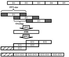
The structure of the FDE with overlap-add one-side zero-padding (OLA-OSZP) method is shown in Fig. 2 [9-12]. The received data are divided into small blocks without any overlap, and then the data in each block are appended with zeros at one side. To be consistent with the OLS method, the total length of data block and zero padding is called the FFT-size, while the length of zero padding is called the overlap. The zero-padded sequence is transformed by the FFT operation, and multiplied by the transfer function of the FDE. Afterwards, the data are transformed by the IFFT operation. Finally the pro-cessed data sequences are combined by overlapping and adding. Note that half of the data stream in the first block is discarded.
D1 D2 D3 FFT-size FDE FFT E31 E32 E21 E22 E12
Received Data Samples
Equalized Data Samples
E12+E21 E22+E31 E32+E41 E42+E51
IFFT
D1 D2 D3 D4 D5
Overlap
Fig. 2: FDE with OLA-OSZP method; the gray parts mean the ap-pended zeros, and the parts with slants are to be discarded
2.3 Overlap-add both-side zero-padding method
The schematic of the FDE with overlap-add both-side zero-padding (OLA-BSZP) method is illustrated in Fig. 3 [9-12]. The received data are also divided into several blocks without any overlap, and then the data in each block are appended with equivalent zeros at both sides. The total length of data block and zero padding is called the FFT-size, and the length of the whole zero padding is called the overlap. The zero-padded sequence is transformed by the FFT operation, and multiplied by the transfer function of the FDE, and then transformed by the IFFT operation. The processed data blocks are
also combined together by overlapping and adding. Note that half of the data stream in the first block is discarded. D1 D2 D3 FFT-size FDE FFT
Received Data Samples
Equalized Data Samples
E12+E21 E22+E31 E32+E41 E42+E51
IFFT
D1 D2 D3 D4 D5
Overlap
E31 E32 E21 E22 E12
Fig. 3: FDE with OLA-BSZP method; the gray parts mean the ap-pended zeros, and the parts with slants are to be discarded
2.4 Minimum overlap in FDE
Actually, the value of the overlap in the OLS method or the zero-padding in the OLA-ZP methods is the pivotal parameter in the FDE determined by the dispersion to be equalized. The FFT-size can be configurable provid-ed it is larger than the overlap (or zero-padding). The required minimum overlap (or ZP) in the OLS or the OLA-ZP method can be calculated from the pulse width broadening (PWB) [1,15],
2 4 1 2 2 2 2 2 2 4 4 2 2
2
z D T c cT T T N P P (2) 2 2 4 4 2 2 4 2 z D T c cT
TP
(3)
where TP is the duration width of a broadened Gaussian pulse, T is the sampling period, and
x denotes the [image:3.595.313.541.355.449.2]nearest integer larger than x.
Table 1: The minimum overlap in FDE; NP: minimum overlap deter-mined by PWB, NS: minimum overlap determined by CD equalization simulation
Fiber length (km) NP NS (NS-NP)/NP (%)
20 8 8 0
40 14 16 14.29
600 158 176 11.39
1000 260 288 10.77
2000 518 576 11.2
4000 1032 1152 11.63
6000 1546 1674 8.28
The minimum overlap (or ZP) in the FDE for different fiber length is illustrated in Table 1. The CD coefficient of the fiber is 16 ps/nm/km. The value NP represents the
minimum overlap (or ZP) calculated from Eq. (2), and the value NS represents necessary overlap (or ZP)
[image:3.595.101.280.497.627.2] [image:3.595.312.539.545.639.2]Journal of Optical Communications
32 (2011) 2
3
provides the significantly meaningful information that the theoretical overlap (or ZP) NP plus about 15%
addi-tional supplement can cover the necessary overlap (or ZP) NS determined in the numerical simulation, which
could achieve the satisfactory CD equalization in practi-cal work for the fiber length up to 6000 km.
For a proper overlap (or ZP) value, a large FFT length may be more efficient. However, it will cost more com-putational complexity and hardware memory resources [16]. The efficient selection of the FFT-size will be discussed later. In our simulation work, the FFT-size is designated as the double of the overlap (or ZP) unless otherwise stated. Therefore, the FDE algorithms can be applied conveniently for equalizing different fiber dis-persion only by determining the required FFT-size.
2.5 Optimization of FFT-size
From the above analysis, the required overlap (or ZP) depends on the fiber dispersion to be equalized, and any integer, provided larger than the overlap, can be theoret-ically selected as the FFT-size. However, an optimal FFT-size can be selected to obtain the minimum com-plexity for frequency domain equalization [16]. The complexity in FDE for different FFT-size using several classical FFT algorithms (such as radix-2 and radix-4 FFT operation) is evaluated by the number of multipli-cations per symbol (Mul/Sym), which can be calculated as [16,17],
1 3 log
6 2
Overlap FFT
FFT FFT
Mul
N N
N C N
N (4)
where NFFT is the FFT-size in FDE, NOverlap is the
[image:4.595.312.540.138.251.2]re-quired overlap (or ZP) derived from the fiber dispersion, and C is a positive constant varying for different FFT algorithms. In classical FFT algorithms, C12 corre-sponds to the radix-2 FFT algorithm (FFT-size equal to power of two), and C38 corresponds to the radix-4 FFT algorithm (FFT-size equal to power of four) [17].
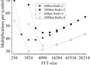
Fig. 4: The complexity for different FFT-size in FDE
The complexity (defined as multiplications per symbol) for 600 km and 2000 km fibers CD equalization using different FFT-size in FDE is shown in Fig. 4. We can see that the optimum FFT-size values to minimize the complexity for 600 km and 2000 km fibers dispersion equalization are 1024 and 4096 respectively in both of the radix-2 and the radix-4 FFT algorithms.
The optimum FFT-size in FDE for different fiber length to minimize the complexity is illustrated in Table 2. We can find that the radix-4 FFT algorithm can achieve a
lower complexity than the radix-2 FFT algorithm. Note that the more sophisticated split-radix FFT algorithms can achieve the lowest complexity for FDE with
3 1
[image:4.595.316.532.505.665.2]C in Eq. (4) [16,17].
Table 2: The optimum FFT-size in FDE for different fiber length
Length (km)
Radix-2 FFT Radix-4 FFT
FFT-size Mul/Sym FFT-size Mul/Sym
20 32 23.04 64 18.53
40 64 26.35 64 20.71
600 1024 38.98 1024 30.12
1000 2048 41.21 4096 32.03
2000 4096 44.63 4096 34.33
4000 16384 48.02 16384 36.82
6000 16384 49.69 16384 38.09
3
NRZ-PDM-QPSK coherent system
The setup of the 112-Gbit/s NRZ-PDM-QPSK coherent transmission system implemented in VPI simulation platform is illustrated in Fig. 5 [18]. The electrical data output from the four 28-Gbit/s pseudo random bit se-quence (PRBS) generators are modulated into two or-thogonally polarized NRZ-QPSK optical signals by two Mach-Zehnder modulators, and then integrated into one fiber channel by a polarization beam combiner (PBC) to form the 112-Gbit/s PDM-QPSK optical signals. Using a local oscillator (LO) in the coherent receiver, the re-ceived optical signals are mixed with the LO laser and transformed into four electrical signals after the photo-diodes, which are then digitalized by the analog-to-digital convertors (ADCs) at twice the symbol rate. The CD coefficient in the transmission fiber is 16 ps/nm/km, and the central wavelengths of the transmitter and the LO lasers are both 1553.6 nm. Here the influences of fiber channel attenuation, polarization mode dispersion, phase noise and nonlinear effects are neglected.
PBS
Qx Ix
Transmission Fiber
X-Polarization
Y-Polarization
LO
PBS PBS
PBC Qx Ix
2x28Gbit/s 215
-1 PRBS
2x28Gbit/s 215-1 PRBS
QPSK
MZI Modulator
Laser
QPSK
MZI Modulator
ADC
ADC
D S P
OBPF
LPF
LPF
PIN
90o
Hybrid
ADC
ADC LPF
LPF
PIN
90o
Hybrid
Fig. 5: The 112-Gbit/s NRZ-PDM-QPSK transmission system
4
Simulation results
[image:4.595.93.245.535.644.2]FFT-Journal of Optical Communications 32 (2011) 2
4
[image:5.595.76.267.108.243.2]size. We can see that both of the OLA-ZP methods can provide the same acceptable performance as the OLS method.
Fig. 6: CD compensation results using OLS and OLA-ZP methods
Figure 7 and Fig. 8 show the performance of CD com-pensation for 20 km and 40 km fibers using OLS and OLA-ZP methods with different FFT-sizes and overlaps (or ZP), respectively.
Fig. 7: CD compensation using OLS and OLA-ZP methods with different sizes at OSNR 14.8 dB; the overlap is half of the FFT-size
[image:5.595.72.259.294.436.2]From Fig. 7 we can see that for a certain fiber length, the three methods can show stable and converged ac-ceptable performance with the increment of the FFT-size. The critical FFT-size values (16 FFT-size for 20 km fiber and 32 FFT-size for 40 km fiber), actually indicate the required minimum overlap (or ZP) value which are 8 overlap (or ZP) samples for 20 km fiber and 16 overlap (or ZP) samples for 40 km fiber. The similar performance demonstrates that for a fixed overlap (or ZP) value, the maximum compensable dispersion in the OLS method is the same in the OLA-ZP methods.
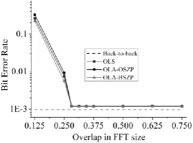
Fig. 8: CD compensation for 4000 km fiber using OLS and OLA-ZP methods with different overlaps at OSNR 14.8 dB; the FFT-size is 4096
We have demonstrated that the overlap (or ZP) is the pivotal parameter in the FDE, and the FFT-size is not necessarily designated as double of the overlap (or ZP). Figure 8 illustrates that with a fixed FFT-size (4096 samples) the three filters are still able to work well for 4000 km fiber, provided the overlap (or ZP) is larger than 1152 samples (1152=4096×9/32), which indicates the required minimum overlap (or ZP) for 4000 km fiber. The minimum overlap (or ZP) in FDE determined from simulation is illustrated in Table 1.
5
Conclusions
For the first time to our knowledge, we present the de-tailed comparative analysis for three types of frequency domain equalization, including save, overlap-add one-side zero-poverlap-adding and overlap-overlap-add both-side zero-padding methods. They are applied to compensate the CD in the 112-Gbit/s NRZ-PDM-QPSK coherent optical transmission system. Our analysis demonstrates that both the two overlap-add zero-padding methods and the overlap-save method can achieve the same perfor-mance in frequency domain CD equalization. The re-quired minimum overlap (or zero-padding) is given out by the analytical expression, and the simulation results show the theoretical overlap plus a 15% additional sup-plement can provide the acceptable equalization per-formance. The optimum FFT-size in FDE is also ana-lyzed to obtain the minimum computational complexity. The radix-4 FFT algorithm can be employed to achieve nearly the same lowest complexity as the sophisticated split-radix FFT method.
References
[1] G. P. Agrawal: “Fiber-optic communication systems”; New York, John Wiley & Sons, Inc., 3rd ed. (2002)
[2] H. Bulow et al.: J. Lightwave Technol. 26 (2008), 158-167 [3] F. M. Abbou et al.: J. Opt. Commun. 28 (2007), 221-224 [4] S. J. Savory: Opt. Express, 16 (2008), 804-817
[5] S. Haykin: “Adaptive filter theory”; New Jersey, Prentice Hall, 4th ed. (2001)
[6] M. Kuschnerov et al.: Proceedings OFC 2009, OMT1 [7] B. Spinnler: Proceedings ECOC 2009, Paper 7.3.6 [8] T. Xu et al.: Opt. Express 18 (2010), 16243-16257
[9] J. G. Proakis, D. K. Manolakis: “Digital signal processing: principles, algorithms and applications”; New Jersey, Prentice Hall, 4th ed. (2006)
[10] N. Benvenuto, G. Cherubini: “Algorithms for communications systems and their applications”; New York, John Wiley & Sons, Inc. (2004)
[11] D. Lowe, X. Huang: IEEE Int. Symp. Commun. and Inf. Tech-nol. (2006), 644-648
[12] Y. Li et al.: IEEE Trans. Wireless Commun. 7 (2008), 4341-4351
[13] K. Ishihara et al.: Electron. Lett. 44 (2008), 870-871 [14] K. Ishihara et al.: Electron. Lett. 44 (2008), 1480-1481 [15] M. Khafaji et al.: IEEE Photonics Technol. Lett. 22 (2010),
314-316
[16] J. Leibrich, W. Rosenkranz: Proceeding OFC 2010, OWV1 [17] A. V. Oppenheim et al.: Discrete-time signal processing, New
[image:5.595.71.269.603.749.2]