STRUCTURES WITH SUPPLEMENTAL LEAD DAMPERS
UNDER EARTHQUAKE AND WIND LOADS
A thesis
submitted in partial fulfilment of the requirements for the Degree
of
Doctor of Philosophy in the
Department of Civil Engineering University of Canterbury
by
Xi Lin
,:;,University of Canterbury Christchurch, New Zealand
THESIS
fH
IO~
ABSTRACT/ -13r
,.,,,. •• c_.::)
This research is carried out to investigate the dynamic behaviour of a 12-storey reinforced concrete framed structure with recently developed lead-shear dampers such as the Penguin Vibration Dampers under earthquake and wind loadings.
For regular framed structures under earthquake excitations, a satisfactory distribution of damper yield strengths in the storeys has been found using the criteria of minimising interstorey drift, base shear and cost of the dampers. The displacement, acceleration and the interstorey drift responses for the structure with supplemental dampers can be reduced significantly. Pushover analyses of the structure with supplemental dampers have been performed and the results have been compared with that of the structure without dampers. Equivalent SDOF system for the MDOF structure with dampers has been obtained through appropriate transformation by means of displacement shape of the structure at the target displacement. For such a distribution of the dampers, the structure with supplemental dampers will behave predominantly in its first mode. The equivalent SDOF system can be used to predict the response of the MDOF structure with dampers with good accuracy. A simplified nonlinear static method, taking into account the effect of the supplemental dampers, has been investigated to conduct the seismic analysis of the structure with dampers. While comparing with the nonlinear time history analysis method, it has been found that this simplified method can give a very good approximation to the response. By investigating the effects on the displacement and acceleration response associated with the supplemental dampers under earthquake excitations, optimal damping levels of the dampers have been found. Based on the simplified nonlinear static method and the optimal damping ratio of the dampers, a displacement-based design procedure has been established to determine the damper yield strengths in the storeys for preliminary seismic design.
ACKNOWLEDGMENTS
This research was carried out in the Civil Engineering Department of the University of Canterbury.
I wish to express my sincere gratitude to Dr P.J. Moss and Dr A.J. Carr for their invaluable advice and encouragement as supervisors of the project. Their kindness, patience and cheerful hearts are greatly appreciated.
I also wish to thank Dr J.X.Q. Zhao in Institute of Geological & Nuclear Sciences Ltd and T. Kelly in Holmes Consulting Group for their providing test results of the prototype PVD, NZS4203 compatible earthquake time histories, useful information and their helpful comments.
Warm gratitude is given to my fellow postgraduates for their encouragement and constructive discussions.
The partly financial assistance provided by Penguin Engineering Ltd 1s gratefully acknowledged.
I wish to thank my family for their prayers, love, understanding and support.
TABLE OF CONTENTS
ABSTRACT
ACKNOWLEDGEMENTS TABLE OF CONTENTS NOTATION
CHAPTER
1. INTRODUCTION
I.I General
1.1.1 Conventional Seismic Design 1.1.2 Structural Control
1.2 Objectives and Scope
2. REVIEW OF TYPES OF SUPPLEMENT AL DAMPERS
2.1 Introduction
2.2 Viscoelastic Devices 2.3 Viscous Liquid Devices
2.3.1 Viscous Walls
2.3.2 Fluid Viscous Dampers 2.4 Hysteretic Devices
2.4.1 Friction Devices 2.4.2 Metallic Devices
2.4.2.1 Yielding Steel Devices 2.4.2.2 Lead Extrusion Dampers 2.5 Other Devices
2.5.1 Energy Dissipating Restraint 2.5.2 Ring Spring Devices
2.5 .3 Tuned Mass Dampers
2.6 Description of A New Lead-Shear Damper
3. MODELLING OF THE INELASTIC STRUCTURE AND THE SUPPLEMENTAL LEAD DAMPERS
3.1 Modelling of the Inelastic Structure 32
3.2 Modelling of the Supplemental Dampers 33
3.3 Modelling of the Inelastic Structure with the Supplemental Lead Dampers 34
4. BRIEF INTRODUCTION TO ANALYTICAL METHODS
4.1 Review of Analytical Methods Used for Structures with Different Types of
Supplemental Dampers
4.1.1 Linear Static Method
4.1.2 Linear Dynamic Time History Method
4.1.3 Simplified Nonlinear Static Method
4.1.4 Nonlinear Dynamic Time History Analysis
4.2 Analytical Methods Adopted For This Study
4.2.1 Time History Analysis
4.2.2 Pushover Analysis
4.2.3 Simplified Nonlinear Static Analysis
4.3 Earthquake Excitations
45
45
46 46
47
48 48 48 49 49
4.4 Comparison of Dynamic Response of the Structure with the Supplemental Dampers
Using Ramberg-Osgood Model and Elasto-Plastic Model 50
5. PLACEMENT AND DISTRIBUTION OF THE SUPPLEMENTAL DAMPERS IN THE STRUCTURE
5.1 Placement of the Supplemental Dampers in the Structure 58
5.2 Distribution of the Damper Yield Strengths in the Structure , 59
5.3 Influence oflnitial Stiffness of the Dampers 62
5.4 Influence of Flexibility of Braces 63
6. PUSHOVER ANALYSIS OF THE STRUCTURE WITH THE SUPPLEMENTAL DAMPERS AND ITS EQUIVALENT SDOF SYSTEM
6.1 Pushover Analysis of the Structure with Supplemental Dampers 6.1.1 Base Shear-Roof Displacement Relationship for the Structure 6.1.2 Displacement Shape of the Structure
6.1.3 Lateral Load Pattern
6.2 Equivalent SDOF System for a MDOF Structure 6.2.1 Introduction
6.2.2 Derivation of Equivalent SDOF System 6.2.3 Influence of the Displacement Shape
6.2.4 Time History Analysis of Equivalent SDOF System 6.2.4.1 Original Structure without Damper
6.2.4.2 Structure with the Supplemental Dampers
7. EQUIVALENT VISCOUS DAMPING RATIO
7.1 Introduction
7 .1.1 Representation of Damping 7.1.2 Equivalent Viscous Damping
7 .2 Equivalent Viscous Damping Ratio due to the Supplemental Dampers 7.2.1 SDOF System
7 .2.1.1 Equivalent Viscous Damping Ratio 7.2.1.2 Effective Period of the SDOF System 7.2.2 MDOF Structure
7 .2.2.1 Equivalent Viscous Damping Ratio 7.2.2.2 Effective Period of the MDOF Structure 7.3 Generalised Derivation of A MDOF Structure
7.3.l Equivalent Viscous Damping Ratio 7.3.2 Effective Period of the MDOF Structure
7.4 Estimate of the Equivalent Viscous Damping Due To the Inelastic Deformation of the Structure
8. SIMPLIFIED NONLINEAR STATIC METHOD
8.1 Introduction 8.2 Pushover Analysis
8.2.1 Lateral Load Pattern
8.2.2 Capacity Curve of A MDOF Structure 8.2.3 Displacement Shape
8.3 Spectral Capacity Curve 8.4 Design Demand Spectra
8.4.1 Elastic Demand Spectra
162 164 164 164 165 165 167 167 8.4.2 Effect of Inelastic Deformation of Structures on Design Demand Spectra 168 8.5 Procedure for the Simplified Nonlinear Static Analysis of
Structures with Supplemental lead Dampers 8.6Example
9. DISPLACEMENT-BASED DESIGN PROCEDURE FOR THE STRUCTURE WITH SUPPLEMENTAL LEAD DAMPERS
9.1 Review of Existing Design Methods for Hysteretic Dampers 9.2 Displacement-Based Design Method Overview
9.3 Apply Displacement-Based Design Concept to Structures with Supplemental Lead Dampers
9.3.1 Generation of Appropriate Displacement Spectra 9.3.2 Target Displacement and Displacement Shape 9.3.3 Characteristics of the Equivalent SDOF System 9.3.4 Optimal Equivalent Viscous Damping Ratio due to
the Supplemental Dampers
9.4 Displacement-Based Design Procedure for Determining Parameters for the Supplemental Dampers for an Existing Structure
9.5 Displacement-Based Design Procedure for Determining Parameters for the Supplemental Dampers for a New Structure
9.5.1 Time-Independent Displacement Shape
9 .5 .2 The Initial Period of the Undamped Structure T 0
9.5.3 Design Procedure
9.6 Influence of the Distribution of the Damper Yield Strengths in the
Structure for a Stepped rather than an Inverted-Triangular Distribution 208
10. SIMULATION OF WIND SPEED AND WIND LOADS
10.1 Introduction
10.2 Structure of the Wind 10.2.1 Mean Wind Profiles
10.2.2 Structure of Turbulence (Fluctuating Component) 10.3 Equivalent Wind Spectrum
10.4 Wind Load Distribution
10.5 Simulation of Artificial Wind Speed Time History
10.6 Comparison of the Response from Time-History Analysis with the One from Code Method
10.6.1 Method Given by Australian Standard for Wind Loads AS 1170 Part2
10.6.2 Numerical Results
11. PLACEMENT AND STRENGTH LEVELS OF THE SUPPLEMENTAL DAMPERS IN THE STRUCTURE
11.1 Placement of the supplemental Dampers in the Structure 11.2 Influence of the Damper Yield Strengths
11.3 Natural frequency and Normal Mode Shape of the Structure with the Supplemental Dampers
11.4 Supplementing Damping Level due to the Dampers
12. SIMPLIFIED ANALYSIS AND DESUGN OF THE STRUCTURE WITH SUPPLEMENTAL LEAD DAMPERS UNDER WIND GUSTS
12.1 Calculation of Along-Wind Deflection and Acceleration 12.1.1 SDOF System
12.1.2 MDOF Structure
12.2 Equivalent Viscous Damping of the MDOF Structure 12.3 Simplified Analysis of the Structure with Supplemental
Dampers under Wind Gust Loading
12.4 Design of the Yield Strengths of the Dampers in the Structure 12.4.1 Design Criteria for Wind-Sensitive Buildings
12.4.2 Design Procedure for Determining the Yield Strengths of the Dampers
271 271
275
13. SUMMARY, CONTRIBUTIONS, CONCLUSIONS AND RECOMMENDATIONS
13 .1 Summary
13.2 Main Contributions of This Research
13 .3 Conclusions for the Analysis and Design of the Structure with Supplemental Lead Dampers under Earthquake Loads
13.4 Conclusions for the Analysis and Design of the Structure with Supplemental Lead Dampers under Wind Loads
13.5 Recommendations for Further Research
REFERENCES APPENDIX
284
285
287
289
290
292
A ax a_,,o ax,d b B C C
[CJ
C*CD
C1z(T,1)
C1 C,n(z) Coh(r,n) D(z,t) E NOTATION
= displacement amplitude = peak ground acceleration
= tributary area perpendicular to wind loads for the ith floor level = peak acceleration
= peak acceleration of the structure without dampers
=
peak acceleration of the structure with supplemental dampers = horizontal breadth of a vertical structure normal to the windstream=
a background factor=
damping coefficient of the SDOF system = a constant of proportionality=
a damping matrix = generalised damping = drag coefficient= basic seismic hazard acceleration coefficient for elastic structures = leeward drag coefficient
= added mass coefficient at height z = square root of the coherence function
=
generalised damping for the rth mode = site-dependent factor=
windward drag coefficient = exponential decay coefficients= drag load force per unit length in a turbulent flow
=
spectrum of turbulence in the approaching wind stream = energy dissipation per cycle= energy dissipated per cycle by the dampers at the ith storey,
=
the energy dissipated by supplemental dampers per cycle for the ith vibration mode= energy dissipated by the dampers per cycle for the rth mode,
=
maximum elastic strain energy= maximum elastic strain energy of the supplemental damping system = maximum elastic strain energy of the undamped structure
F(z,t)
{F}
{Fv(u)} F Fd F~(z,t) Fv(z) F; F;(z) F;'(z,t) Fyd Fydl Fydi g G h H H(n) h1 mode=
strain energy of the rth mode of the structure with dampers=
drag force due to wind loads=
lateral force vector'
=
supplemental damping force vector=
force=
damping force=
fluctuating drag due to wind loads at height z=
mean drag due to wind loads at height z=
the ith term of the lateral force vector{F}
=
mean drag at the ith floor level due to wind loads=
fluctuating drag at the ith floor level due to wind loads=
the force factor=
effective first yield of the structure with dampers=
yield base shear of the undamped MDOF structure=
yield base shear of the equivalent SDOF for the undamped structure=
yield strength of the damping system for the equivalent SDOF system=
yield force of the SDOF spring representing supplemental damping system=
yield strength of the damper at the 1st floor level=
yield strength of the damper at the ith storey,=
acceleration due to gravity=
the gust factor=
a peak factor, the ratio of the expected peak value which occurs once per hour to the variance of the resonant part of the fluctuating response=
a peak factor for the upwind velocity fluctuation=
a constant for hysteretic dampingor
=
the height of the building structure, in metres=
height of the building structure=
the mechanical admittance function= 0. 607h = the reference height
=
height of level i relative to the ground,JDimax K Ksec,d Ksec,s
L*
m m [M] M A M m;M (z ,cat)
N
= peak interstorey drift index
= von Karman coefficient (approximately 0.4) or = stiffness of the structure
= initial elastic stiffness = stiffness of a brace
= stiffness of a brace-damper assembly in the elastic range = initial stiffness of dampers
= effective stiffness of the structure with supplemental dampers
= effective secant stiffness matrix of the structure at the target displacement
=
generalised stiffness for the rth mode= initial elastic stiffness of the undamped structure (for the SDOF system)
=
initial storey stiffness of the undamped structure=
secant stiffness of supplemental damping system=
secant stiffness of the undamped structure=
nondimensional coefficients= mass of the equivalent SDOF system
=
a measure of the effective turbulence length scale, in metres=
limit state factor for the ultimate limit state(= 1) = mass of the SDOF system=
mass per unit height = a diagonal mass matrix=
mean overturning moment of the structure due to wind loads = expected peak overturning moment due to wind loads = total building mass, kg= mass at level i
=
limit state multiplier=
structure risk multiplier= generalised mass for the rth mode = shielding multiplier
= topographic multiplier
=
site terrain/height multiplier = an effective reduced frequency or = number of frequency intervalsn1
=
first mode along-wind frequency of the building, in Hertz n;=
the ith mode frequencyT = duration of wind time history
p
=
load factorp(v) = probability density ofv
P
=
elastic force of the SDOF system for the undamped structureRPI
=
relative performance indexPy
=
yield force of the SDOF system for the undamped structureQ
=
base shear of the MDOF structure at the target displacement,Q1 = peak base shear of the MDOF structure
r
=
constant which controls abruptness of loss of stiffness in the Ramberg-Osgood hysteresis loop modelor = a roughness factor, twice the longitudinal turbulence intensity
or= ratio of the post-yield stiffness to the initial stiffness of the undamped structure
or
=
distance between points 1 and 2r(t)
=
nonlinear restoring force of the SDOF system,{r}
=
displacement of the structure due to a unit ground displacement in theR
{R(t)}
R*
Rt*
{RY(t)}
s
Sa(T,;)s
Jr.,ff , ;, )
direction of earthquake excitations
=
retum period in years or=
risk factor for a structure=
resistance vector,=
elastic base force of the equivalent SDOF system for the undamped structure=
ratio of the peak acceleration of the structure with dampers to that of the structure without dampers=
peak force of the equivalent SDOF system=
yield force of the equivalent SDOF system=
yield resistance vector of the MDOF structure=
a size factor to account for the correlation of pressures over a structure=
spectral acceleration=
spectral acceleration for the effective period T eff and the equivalent viscousdamping ratio ~t
=
target spectral displacement for the equivalent SDOF systemSEA SEA<o) SF{n) SM(n) Sp
SR
Sv(n) S,,(zpn)Svc: (r,n)
I 2
T u it
u
Ut U,11ax {ur} v(z,t) V(z,t) V(z) Vo= the area under the strain energy time-history for a friction damped structure
=
the area under the strain energy time-history for the undamped structure = power spectrum of the fluctuating drag= power spectrum of the overturning moment = structural performance factor(= 0.67) = the stiffness factor
=
power spectral density function of the turbulence component= power spectral density function of the along-wind components of turbulence at height zl
= the cross spectrum
= power spectral density function for the "reduced equivalent velocity fluctuation", is called the "reduced equivalent wind spectrum" = period of structure
= initial period of the undamped structure
= natural period of the braced structure (no slippage occurring) = effective period of the structure with supplemental dampers
=
the predominant ground motion period,= relative displacement of the mass m with respect to the ground
=
relative velocity of the mass m with respect to the ground=
relative acceleration of the mass m with respect to the ground = displacement vector of the structure= ground acceleration due to a earthquake excitation = lateral displacement of the structure at the ith floor level
=
maximum strain energy for a friction damped structure = the maximum strain energy for the undamped structure=
the rth mode displacement vector of the structure=
turbulence (fluctuating) component of wind speed at height z=
wind speed at a height z=
mean wind speed at height z above ground,=
friction velocity= the total optimum slip shear,
=
indicate that the two records are taken at points 1 and 2w W; x(t)
x
x'(t) X x* Xr(t) x,,r Xyz
Zo ZGa
a
A; AU"reduced equivalent velocity fluctuation"
=
velocity field of an "equivalent wind structure"=
mean gradient velocity=
design hourly mean wind speed at height h=
a factor to account for the second order effects of the turbulence intensity=
seismic weight at level i,=
displacement at the roof level=
mean displacement due to wind loads=
fluctuating component of the displacement due to wind loads=
expected peak displacement due to wind loads=
displacement of the equivalent SDOF system at the target displacement=
generalised displacement at the rth mode=
peak displacement of the equivalent SDOF system=
peak roof displacement of the structure at the rth mode,=
peak roof displacement of the MDOF structure=
yield roof displacement of the undamped MDOF structure=
yield displacement of the equivalent SDOF system=
zone factor=
roughness length=
the gradient height=
a constant related to the mass matrix in Rayleigh's damping model=
power law exponent=
a constant related to the stiffness matrix in Rayleigh's damping model=
aerodynamic admittance function=
displacement=
deformation of the damper at the 1st floor level=
the displacement of the supplemental damping system at rooflevel,=
damper deformation at the ith storey at the target displacement=
deformation of the dampers at the ith floor level=
energy dissipated per cycle when the system is steadily excited by an imposed forcing function1).:
0 = yield roof displacement of the equivalent SDOF for the undamped structureL1y0 = yield roof displacement of the undamped MDOF structure
q,
1=
yield deformation of the damper at the 1st floor levelL1yd,i
=
yield deformation of the damper at the ith storey, L1yd=
yield deformation of the supplemental dampers!).*yd
=
yield displacement of the SDOF spring representing the supplementaldamping system,
L1y;
=
yield deformation of the damper at the ith floor level </i.._z)=
mode shape{¢}
=
normalised deflected shape vectortpi
=
value of the normalised deflected shape vector at the 1st floor level¢;
=
the ith term of the normalised deflected shape { ¢}'Pi.r
=
value of the rth normalised mode shape at the ith floor level{¢
r}
=
the rth mode shape vector17
=
loss factor for hysteretic dampingor
=
ratio of the area enclosed in the hysteresis loop versus the area of the parallelogram [4FY(umax -
uy )]µ
=
ductility of structure0
=
angle of the diagonal brace relative to the horizontal0;
=
random phase angles uniformly distributed between O and 2nVeq
=
equivalent damping coefficient ratio defined by Jacobsenp
=
air mass densitycrnF
=
variance (rms) of the background (non-resonant) component of thefluctuating force
=
variance (rms) of the background (non-resonant) component of the displacementcrnF
=
variance (rms) of the resonant component of the fluctuating forcecrnM
=
variance of the resonant dynamic component of overturning momentcrnx
=
variance (rms) of the resonant component of the displacementav
=
variance of the turbulence component of along-wind velocity crx=
variance of the fluctuating component of the displacementa..
=
variance of roof acceleration~11!, ~112
= fraction of critical damping
=
initial viscous damping ratio of the structure= equivalent viscous damping ratio due to supplemental dampers
=
equivalent viscous damping ratio for the ith vibration mode= two fractions of critical damping for the m 1 mode and m2 mode
=
total equivalent viscous damping ratio of the structure with supplemental dampers{Vf}
= normalised lateral load vectorlf/i
=
the ith term of the normalised lateral load pattern vector?
= a constant for Coulomb damping ( or frictional damping)?1,
?2
,S3 ,S4 = four different definitions of damping capacityor'
=
circular :frequency for the equivalent SDOF systemCHAPTERl INTRODUCTION
1.1 GENERAL
1.1.1 Conventional Seismic Design
The criteria for the seismic design of ductile structures set by many countries have been that buildings should be able to resist moderate earthquake without structural damage and be able to resist severe earthquake without collapse but perhaps with some structural and non-structural damage. To satisfy these design criteria, structures should be designed to have (Park, 1992):
• Adequate strength and stiffness to satisfy the serviceability limit states when responding to moderate earthquakes.
• Adequate strength, stiffness and ductility to satisfy the ultimate limit states when responding to severe earthquakes.
A basic principle in structural design against severe earthquakes is to allow the structure to absorb and dissipate energy through structural ductility. New Zealand codes (NZS4203, NZS3101) require that ductile structures be the subject of "capacity design". In the capacity design of structures, appropriate regions of the primary seismic-resisting structural systems are chosen and carefully designed and detailed for adequate strength and ductility for a severe earthquake. All other regions of the structural system, to prevent other possible failure modes, are then provided with sufficient strength to ensure that the chosen means for achieving ductility can be maintained throughout the post-elastic deformations (Park, 1992).
1.1.2 Structural Control
Structural control is to add energy dissipating devices to a structure or to isolate the structure from dynamic excitations ( earthquake ground motion and wind load). There are two types of structural control systems: active control and passive control.
Active control is a type of structural protection in which the motion of a structure is controlled or modified by means of the action of a control system through some external energy supply.
The concept behind passive control is to add energy dissipating devices to a structure. The basic function of passive energy dissipation devices when incorporated into a structure is to absorb a portion of the input energy, thereby reducing energy dissipation demands on the primary structural members and minimising possible structural damage. Unlike active control systems, there is no need for an external supply of power.
There are two major passive control systems: base isolation and energy-absorbing devices (or supplemental damping devices). These are shown in Fig.1-1.
Base isolation is a seismic design strategy that reduces the level of ground motion which a structure undergoes during an earthquake by moving the period of the structure away from the predominant period of the ground motion and by increasing the equivalent damping level of the structure by hysteretic behaviour of the isolation devices. This can be achieved by introducing a flexible energy-absorbing connection, usually at the foundation level, between the structure and the ground (Skinner et al., 1993).
Many energy-absorbing devices have been proposed and studied for applications for seismic mitigation of buildings. Some of the major energy-absorbing devices in use include viscous dampers, hysteretic dampers, mass-effect dampers, etc (Fig.1-1 ).
1.2 OBJECTIVES AND SCOPE
The aims of this research project were to
• Determine the satisfactory placement and distribution of the dampers in a structure under earthquake and wind loads;
• Determine appropriate design parameters of the dampers for the structure;
• Establish design procedures for structures with the dampers under earthquake and wind loads.
To achieve the above-mentioned objectives, the following tasks were undertaken:
• Review different types of supplemental dampers.
• Model a 12-storey reinforced concrete structure with supplemental lead dampers.
• Perform seismic time history analyses of the structure with the dampers for different placements, yield strength distributions and stiffness.
• Determine a satisfactory distribution of the dampers in the structure under earthquake excitations.
• Perform pushover analyses of the structures with the dampers, and compare the results with those of the original structure without dampers. Obtain the equivalent SDOF system for a MDOF structure with the dampers and verify such transformation.
• Estimate the effect of the dampers by means of the equivalent viscous damping and effective period of the structure with the dampers. The influence of inelastic deformations of the original structure will also be taken into account.
• Investigate the seismic simplified nonlinear static analysis method and extended its application to MDOF structures with the lead dampers.
• Establish a displacement-based design procedure for structures with the dampers for both existing and proposed structures under the design earthquake.
• Simulate artificial wind speed time history to carry out time history analyses of the structure with the dampers under wind gusts.
• Investigate placement and distribution of the dampers under wind loads.
~
ACTIVE CONTROL SYSTEMS
I
I
PASSIVE CONTROL SYSTEMS> > >
Q Q r:, ,. ,. ,.
< < <"
"'
"'
"',---B_A_S_E_I_S_OLA_T_IO_N--,1 ,_I _ _ E_N_E_R_GY_-_A_B_S_O_RB_I_N_G_D_E_V_IC_E_S _ ____,JI
n a: ..,;
0
"'
"' ::, l'D ::,,.
.,
l'D 0. 02. ::,
..
+ r.i' 0 ;-,. 0 ::,
~~~
:::0 n !:!a ti.I
2. 0
;;-;, 3 C:
"'
.,
CTs·
<S' QQ
"'
c:, 0.
"'
Cll"'
Q. 3!"'
'<.,
!:!a l'D ;,
5· ,.
C:
"'
..
QQ 3
ra S" l'D
QQ I c:,
"'
"'
:i ::, QQ ~ ra ,."'
3ra
a, !:!a ..,; s
g
< t"" :;.i --<"' C: ;;;· "' [
"'
0 ::, fll"'
;:;·.,
..
Q Q 0.0.
::r
"'
0 r:::, 0 ,...5·
S' Q. C:
"'
"'
c::,o·
5'11'2 I f4 3
;-"'
::, 11'2l'D IIQ a: I
,,
fl)
3
i
l'D"'
r:::,"'
,.. r:::, ti.)"'
id Q,,
"'
,.l'D 3
"'
<"'
::,
t/l ., ;:;· !!.
:,;- r:::,
,,
l'Dfll
"'
::r"'
"'
"'
l'D r:::,3 Q.
"'
"'
,,
~.,
<"'
;:;·.,
~ t:,"'
fll iii'
"'
f/J3
,,
n,.,
[image:22.853.134.724.85.452.2]l'D
CHAPTER2
REVIEW OF TYPES OF SUPPLEMENTAL DAMPERS
2.1 INTRODUCTION
Many energy-dissipating devices (supplemental dampers) have been proposed and studied for possible applications for seismic mitigation (or wind resistance) of buildings. They can be classified as either: velocity-dependent, displacement-dependent or other (ATC-33.03). Velocity-dependent devices include viscoelastic and viscous liquid devices. Displacement-dependent devices include friction devices and metallic devices. The third classification ( other) includes all devices that cannot be classified as either velocity-dependent or displacement-dependent. Examples of other devices include shape-memory alloys, friction-spring assemblies with recentering capacity and tuned mass dampers.
2.2 VISCOELASTIC DEVICES
Viscoelastic dampers have been used in both seismic and wind applications. Mahmoodi (1969, 1986) and Keel et al. (1986) investigated the characteristics of viscoelastic dampers and their application to wind design. The characteristics and suitability of viscoelastic dampers to enhance performance of structures under earthquake excitations were studied by Lin et al. (1988), Aiken et al. (1990, 1992), Chang et al. (1991) and Lobo et al. (1993).
Viscoelastic (VE) dampers are normally made of viscoelastic layers bonded to steel plates that dissipate input energy under direct shear. Fig.2-1 shows a currently used VE damper that is comprised of two viscoelastic layers bonded to three parallel rigid surfaces.
The behaviour of viscoelastic dampers is controlled by the shear in the viscoelastic layers. The dynamic behaviour of viscoelastic materials is strongly dependent on temperature and frequency and is also affected by strain amplitude.
expressed as having two components: the viscous force and elastic restoring force. Typical hysteresis loops of viscoelastic devices are shown in Fig.2-2
Some characteristics of viscoelastic dampers are:
(1). They have no threshold or activation force level, thus they dissipate energy for all levels of earthquake excitation and wind gust even while the structure remains elastic or at the early stages of cracking.
(2). They can be manufactured to add significant damping to building frames for improved structural response. The hysteretic characteristics of dampers are functions of shear strain level, excitation frequency, damping material type, thickness and temperature.
(3). They also make a substantial contribution to the initial stiffness of the structure. While the stiffening effect may lead to better control of lateral deformations, the same stiffening may lead to larger seismically induced forces for various ground motions.
2.3 VISCOUS LIQUID DEVICES
Viscous liquid devices are those dampers that depend upon the flow of fluid to achieve energy dissipation. The fluid shows viscous characteristics. These devices include viscous damping walls and fluid viscous dampers (orifice fluid dampers).
2.3.1 Viscous Walls
Viscous damping walls consist of a plate moving in a highly viscous fluid which is contained in a thin steel case (the wall) filled with the highly viscous fluid (Reinhom et al., 1995b). See Fig.2-3.
The basic mechanism of a viscous wall is that it utilises an upper plate moving through a highly viscous fluid between the lower walls (viscous fluid container) and is based on Newton's Law of Viscosity. The viscous resisting force Qw and energy absorbing capacity ~v
viscous wall is a result of the viscous resistance of the viscous fluid against movement of the upper steel plate.
2.3.2 Fluid Viscous Dampers
The fluid viscous damper consists of a cylinder and stainless steel piston with a bronze orifice head and an accumulator (Constantinou et al., 1992, Reinhom et al., 1995a). The cylinder is filled with silicone oil having stable properties over a wide range of operation temperatures. The orifice flow may be compensated in a variety ways so that the mechanical characteristics of the devices are nearly unaffected by temperature. The orifice configuration and mechanical construction can be adjusted to produce various flow characteristics and complex resisting forces. The dampers show strong :frequency dependence. The damper construction detail is shown in Fig.2-4.
The common characteristic of the two dampers discussed above is that the "viscous" behaviour of dampers provides the main contribution of forces that reduce the structural response. Both viscous walls and fluid viscous dampers have a strong :frequency dependency.
The major distinction between these two dampers is:
The fluid viscous dampers show minor stiffening characteristics within the :frequency range of interest while introducing a large amount of damping into the structure. The viscous walls show significant stiffening characteristics within the :frequency range of interest while introducing a large amount of damping into the structure.
2.4 HYSTERETIC DEVICES
Hysteretic devices are devices that can dissipate energy through inelastic deformations of their components or friction within their parts or surfaces.
The main goals in the structural layout of a hysteretic device system are (Dorka et al., 1994):
(2) To concentrate the structural deformations in the hysteretic devices to dissipate most of the input energy.
Goal (1), in particular, distinguishes hysteretic device systems from systems that use dissipaters only to enhance damping: A hysteretic device system has a shear force envelope chosen by the designer.
There are several different dissipative mechanisms having been utilised in hysteretic devices: Friction, metal yielding and re-crystallisation (lead).
2.4.1 Friction Devices
There are a variety of friction devices that have been proposed for structural energy dissipation. Friction systems usually generate rectangular hysteresis loops which are characteristic of Coulomb friction. Typically these devices have very good performance characteristics, and their behaviour is not significantly affected by load amplitude, frequency or the number of applied load cycles.
Friction devices have been developed and manufactured for many years by Sumitomo Metal Ltd, Japan (Fig.2-5). A similar type of friction dampers has been manufactured by Tekton company, Arizona (Fig.2-6) (Li et al., 1995). Pall et al. (1982, 1987) proposed a friction device located at the intersection of cross bracing (Fig.2-7). Filiatrault et al. (1987) and Aiken et al. (1990) confirmed that these friction devices could enhance the seismic performance of structures.
Some characteristics of friction dampers are:
(1) The dissipated energy increases proportionally with increases in the exciting displacement. Further, the damping ratio also increases within a certain range of excitation level.
(3) The period of the structure varies with the intensity of the earthquake that will shift the structural frequency away from the resonant frequency.
(4) The hysteretic behaviour of dampers provides the main contribution to the reduction of
the structural response.
2.4.2 Metallic Devices
Metallic devices are a type of energy dissipation system that takes advantage of the hysteretic
behaviour of mild steel or lead when deformed in their post-elastic range. A wide variety of
different types of device utilise flexural, shear or extension deformation modes into the inelastic range (Fig.2-8). The idea of utilising separate metallic devices within a structure to
absorb a large portion of seismic energy started with the work by Kelly et al. (1972) and
Skinner et al. (1975). A particularly desirable feature of these systems is their stable
behaviour, long term reliability and generally good resistance to environmental and
temperature factors.
The resisting force of metallic energy absorbers depends on the nonlinear stress-strain
characteristics and geometrical configuration of the material.
The two most commonly used materials are mild steel and lead.
2.4.2.1 Yielding Steel Devices
A wide variety of devices that utilise the ability of mild steel to sustain many cycles of stable
yielding behaviour have been proposed. An energy absorbing device in the form of round mild steel rod with a rectangular shape, introduced at the intersection of cross bracing, has
been developed in New Zealand (Tyler, 1978, 1985, see Fig.2-9). Many of these devices _
making use of mild steel plates with different shapes have been proposed. For rectangular
plates, the plastic deformation is limited to occurring at a finite region at the ends. For
triangular or X shapes, the yielding occurs almost simultaneously throughout the entire height
One such device that uses X-shaped steel plates is the so-called Added Damping And Stiffness (ADAS) devices (Whittaker et al., 1989, Scholl, 1990). Another device that uses triangular plates is called the Tapered-Plate Energy Absorber (TPEA, Pong et al., 1994) or T-ADAS (Tsai et al., 1993). These devices are shown in Fig.2-11 and 2-12.
Some characteristics concerning ADAS (or T-ADAS) devices are:
(1) ADAS devices installed in building frames are able to increase the stiffness, strength and energy dissipation capacity of structures. It is often desired that the ADAS devices will remain elastic under wind gusts and yield under major earthquakes.
(2) The ADAS device has excellent ductility without fatigue problems and exhibits stable behaviour without any sign of pinching or degradation.
(3) Yield forces and yield displacements of ADAS elements can be readily varied throughout the height of a structure to improve the distribution of ductility.
(4) The behaviour is not significantly affected by frequency and the number of applied load cycles.
2.4.2.2 Lead Extrusion Dampers (LEDs)
The Lead-Extrusion Dampers are energy absorbing devices that convert mechanical energy to heat through the cyclic deformation of lead (Robinson, 1976, Cousins et al., 1993). Robinson (1976) found that the process of extrusion whereby a metal is forced through an orifice would be a very efficient method in that the metal is grossly deformed and the energy absorber should behave as a "plastic solid". Since lead recrystallises at room temperature thereby recovering most of its mechanical properties almost immediately after plastic deformation, lead was chosen as the metal to be extruded.
There are two basic versions of the lead extrusive damper (Cousins et al., 1993). In one version, called the "constricted tube" damper, a billet of lead is forced to extrude back and forth through an orifice that is formed by an annular constriction in the surrounding tube. In the other version, the "bulged shaft" damper, the orifice is created by a bulge on a central shaft that moves back and forth through the lead billet. These two versions of the lead extrusion damper are shown in Fig.2-13. Typical load-displacement hysteresis loops for lead extrusion dampers are shown in Fig.2-14.
Some characteristics of a Lead Extrusion damper (Robinson et al., 1976) are:
(1) It is almost a pure "Coulomb damper" in that its force-displacement hysteresis loop is nearly rectangular and is practically rate-independent at earthquake-like :frequencies.
(2) Because the interrelated processes of recovery, recrystallization and grain growth occur during and after the extrusion of the lead, the energy absorber is not affected by work hardening or fatigue, but instead the lead is forever returning to its original undeformed state. The extrusion damper therefore has a very long life and does not have to be replaced after an earthquake.
(3) The extrusion damper is stable in its operation and can not destroy itself by building up excessive forces.
(4) The length of stroke of the LED is limited only by the problem of buckling of the shaft during compression.
2.5 OTHER DEVICES
2.5.1 Energy Dissipating Restraint (EDR)
defined as the relative motion of the shaft with respect to the cylinder. The resistance of the device is provided by frictional forces that develop between the bronze frictional wedges and the internal cylinder wall (lnaudi et al., 1993).
The EDR can have different configurations to provide several hysteretic behaviours. Different mechanical behaviour can be obtained by changing the pre-load of the spring and the lengths of the tension and compression gaps. Two configurations of the EDR have been studied by Inaudi et al (1993). One yields triangular hysteresis loops and the other gives flag-shaped hysteresis loops under cyclic deformation (Fig.2-16).
The overall effect of the EDR is to substantially reduce the structure deformations and interstorey drifts. Part of the change in structural response is due to the change in the stiffness of the structure when the ED Rs are added and part is due to the additional damping the EDRs add to the structure. One advantage of the EDR is that it can be effective at low seismic levels or for wind loading while also being effective at high seismic levels. This is because the slip forces, and thus the energy dissipated, are proportional to the displacement of the EDR. Another advantage is that the self-centring behaviour would tend to reduce permanent offsets if the structure were deformed inelastically (Aiken et al., 1992).
2.5.2 Ring Spring Devices
Ring springs are frictional devices consisting of inner and outer ring elements assembled to form a spring stack. A prototype ring spring cartridge that allows bi-directional dynamic inputs to be applied to ring springs was designed and manufactured in the Department of Mechanical Engineering, University of Canterbury, New Zealand (Hill, 1995).
The ring spring cartridge primarily comprises of an outer housing and an inner shaft. The outer housing enable attachment as its end and the inner shaft locates and provides guidance for the ring spring. Pistons are used at each end of the spring to accommodate bi-directional displacements. Each piston is lined with 3mm thick rubber to cushion contacting as the cartridge undergoes displacements (Fig.17)
An innovative pivotal rocking seismic isolation systems (PRSIS) for protecting columnar structures during earthquake has been built and tested (Hill, 1995). Configuration of the PRSIS is shown in Fig.20. Test results show that the PRSIS is effective in reducing structural loads and is able to provide significantly improved protection for structures that have fundamental periods in the range of dominant earthquake spectral acceleration.
2.5.3 Tuned Mass Dampers
The objective of incorporating a tuned mass damper into a structure is basically the same as those associated with other energy dissipation devices, namely, to reduce energy dissipation demand on the primary structural members under the action of external forces. This reduction, in this case, is accomplished by transferring some of the structural vibrational energy to the tuned mass damper (TMD) which, in its simplest form, consists of an auxiliary mass-spring-dashpot system anchored or attached to the main structure.
Sladek et al. (1980), motivated by published literature that reported the use of TMDs could reduce wind induced accelerations of high rise buildings by as much as 40%, investigated the possible use of vibration absorbers in reducing the seismic response of tall buildings. In their study, they considered three vibration absorbers: a tuned mass damper (TMD), a variable tuned mass damper (VTMD) and an anticipatory vibration absorber (AV A). It was found that the TMD, VTMD and AV A were ineffective in reducing the maximum seismic response of tall buildings.
Almost all TMD applications have been made towards mitigation of wind-induced motion. Seismic effectiveness of TMDs remains to be an important issue. It can be generally stated that, under earthquake-type loading, TMDs are not as effective as for wind-type loading due to the following reasons (Soong, T.T. et al., 1997):
(b) As pointed out by a few investigators, the first peak in the response history cannot be easily reduced due to the fact that TMD passively responds to the structural movement and then reversely mitigates the response of the structure by vibrating out-of-phase with the structural movement.
There are some other energy-dissipating devices. Some of these are shape memory alloy (Witting et al., 1992), tuned liquid dampers etc. Details can be found in the textbook written by Soong et al. (1997).
2.6 DESCRIPTION OF A NEW LEAD-SHEAR DAMPER: PENGUIN VIBRATION DAMPER (PVD)
A new compact lead-shear damper, the PENGUIN VIBRATION DAMPER (PVD), has been developed recently by PENGUIN ENGINEERING Ltd (Monti et al., 1996). This is a compact damping device to be used as supplemental damping for tall and/or flexible structures (Fig.2-21 ). The damping of this device is achieved through the plastic deformation of a lead core. It is capable of sustaining thousands of cycles at any amplitude within its design range, without deterioration or requiring maintenance. This is achieved through dynamic and meta-dynamic recrystallization oflead (Monti et al., 1995).
This device is sensitive to very small displacement. Significant hysteretic damping can be achieved at displacement as low as ±2 micro metres. A standard device is sensitive to movements as small as ±2 microns such as expected in wind induced vibration, to ±10 mm as expected in a large earthquake. Larger devices have displacement capacity of up to ±1 metre. However, the sensitivity decreases as size increases. Associated damping forces range from
lKN to lO00KN (Monti et al., 1996).
PLAN
1 - - - - -9.00
-1__ _ _ _ _ _ _ _ _ _ _ _ _ _ 0.15 th;ck VE noter;ol
J.50
$
$
- , - '----i;;;;;;;;;;;;;;;;;;;;;;;;;;;;;;~~---+--~ __J_
.1___
- - L
--L
o.375Lh_ 0.25
J.50 'V
~-50
-1
L2.00J 0.625 dlo.5 . 0 0 -ELEVATION
, 5 . 0 0
[ 0.5875
_I -
c=========~===========l
0.25
r-$
$
t
t
1.825 3.00
$
_ I0.625 dlo.
1-
1.00All dimensions in inches
ISOMETRIC VIEW
[image:34.616.105.495.95.632.2]0
0
Stress
•
Stresst
Stress.
G' "{ + G" "/G'"{
I
G""{,,,.
+
Strain,
y
~ ·
-Strain,
y
(a) Steady-State Hysteresis Loops for Viscoelastic Material
Force Force Force
K'x Ceqx K'x
+ C8qx ... -..J
+
Displacement, x
Displacement, x Displacement, x
(b) Steady-State Hysteresis Loops for Direct Shear Seismic Damper (OSSO)
inner
plate
viscous
fluid
outer
plate
~ -20
-~
I
.
---·
---=r--I=
.
-
--
~_,
--.
=~---·
LOADCBLL
:
...~ -30 • . ···:···:···
0:: • • • •
-.c.o ... i ... ,t ... ; ... ; ... ; •••••• : ... : ... , ... ..
: : : : Dlsplace•ent d(c11)
-50'---~ ... '---~---~
-!iO-40 -30 -20 -10 0 10 20 30 -40 50
•
SEAL RETAINER
PISTON ROD
CYLINDER
COMPRESSIBLE SILICONE FLUID
ACCUMULATOR HOUSING
--ACCELEAXIO~ CIRCUIT
STAGNATXON
CHAMeER
F1uiclic Contro1 Ori~ice
COMP'RESSIBLE FLUID ME.DX\.JM
Figure 2-4. Detail of a fluid viscous damper (from Li et al., 1995)
(a) Longitudinal Section
inner wedge
outer wedge
outer cylinder
friction pad
cup spring
(b) Cross Section
outer wedge (in 3 parts)
ADJUSTABLE NUT (TORQUE CONTROLLER)
SPRING
7
A
STEEL WITH FRICTION PAD
~
MOVING RODI :
I
:::.::::: :
C::::::]
1:::1 ========A-=A=s=Ec=11=o=N==::::::=:===~1
~r
j
i - - 1 s " - ~ s " = l
b). Detail of Friction-Device
'
"
•
ct. Hysteresis 4 oop of Device
Figure 2-7. Friction device by Pall (from Pall et al., 1987)
2r
ANCHOR
(a) U-STRIPS
PHERICAL ZONE
(c) FLEXURAL BEAM
.(b) TORSIONAL BEAM
0
l
(d) SINGLE-AXIS DAMPER A
e OI
,.:,
soomm
Elevation of Bracing_
in building_
RODS
~
PITCH OF BRACE
ROD RINGS
ROO BRACING. THREAD
PLATE STRESS
CONFIGURATION PROFILE DEFORMATION DISTRIBUTION COMMENTS
I[
f
Non-Workable
Rectangle due to local
'
yielding
+\+
onlyTriangle
-1
Workable~
+fy+
_,.
X Shape Workable
+ - - - 7 . 7 5 - - - + - - - - 5 . 7 5 - - - +
f+-1.25-<f f+-1.25,-+{
T
2.00
1
[:
-- - ----u
-- - I
---lo.125
5.00 ~ i+-0.25
j,--2.00--+j
l
0
0
r
1.00' - - - ~ j_
- - - - 5 . 0 0 - - -...
[:
--- -
--:a
-
-All dimensions in inches
(a)
1 5 , - - - . - - - , Tesl 880706.06
·10
- 1 5 ~ - ~ - ~ - ~ - - - ' - - ~ - ~ -0.6 -0.4 -0.2 0.0 0.2 0.4 0.6
Oiaplacemenl (inoh)
(b)
1 5 . . . - - - r - - - ,
Teal 880708.15
10
2 -1s_,,_2 _ _ __,,_,,---=o---~
Oiaplacemenl (inch)
( c)
s:
;g,~ if :; .! "' 10 D -5 -10 -15 •3 Tul 8M>706.17
-2 -1 0
Diaplacemenl Onch)
T
2.0011
5.00)
2.00l
2 3
N
569
:1::n :n :r: tm\ :r: ='i' m
(unit: 111111)
Beam
\ _ Bracing (fYP.)
, l,-sa1
TPEA Device
Oetal.l A
Orifice
Seals
Orifice
Bearings
Figure 2-13. Longitudinal section of cyclic lead extrusion damper: (a) constricted-tube type (b) bulged-shaft type (from Skinner et al., 1993)
z -"'
'O
0 0
J
100
0
-100
-200 .__ _ _ ..__ _ _ ..._ _ _ ...__ _ _ ..._ _ _ ....__ _ __,
-150 -100 -50 0 50 100 150
Displacement (mm)
[image:44.613.156.455.73.310.2](a}
STEEL COMPRESSION WEOGES
INTERNAL STOP
©x~I-===---=--CYUNOER WALL
SPRING
BRONZE FRICTION WEDGES (lYP 6 Pt>.CES)
Figure 2-15. External and internal views of the Energy Dissipating Restraint (EDR) (from Inaudi et al., 1993)
Force
Force
Deformation
SPHERICAL ROD [NO BEARING
Deformation
energy
2 absorbed
DEFLECTION
3
Figure 2-18. Force-deflection diagram for zero pre-displacement ring springs (From Hill, 1995)
2
DEFLECTION
6
4-
o
0
o
o
0
o
-~-
~-- -- -- -- -- -- 2 5 0 . 0 -- -- -- -- -- . . . ; , , j , c < -- -- -- -- -- -- 2 5 0 . 0 -- -- -- -- -- -- a . i
Figure 2-20 Pivotal rocking seismic isolation system (PRSIS) (From Hill, 1995)
7
0ci
~
0 0 0
I()
w
Figure 2-21. The self contained lead-shear damper {from Monti et al., 1996)
-
z
~
-
Cl)~
0
LL
300
"""
-
-
---
--
-
-200 100
0
-100
-200 -300
-6 -4 -2 0 2 4
Displacement (mm)
Figure 2-22. The force-displacement curves from tests {from Penguin Engineering Ltd)
CHAPTER3
MODELLING OF THE INELASTIC STRUCTURE AND THE SUPPLEMENTAL LEAD DAMPERS
3.1 MODELLING OF THE INELASTIC STRUCTURE
The inelastic analysis of structures subjected to earthquake loading is usually performed using step-by-step integration of the equations of motion. These equations of motion can represent the dynamic behaviour of structures with variable stiffness due to cracking, yielding, -deterioration and secondary effects, etc.
The equation of motion for the structure subjected to earthquake excitations can be written as:
[M
]{ii}+ [c]{z,}+
{R(u)}=-[M
]{r}iig
(t) (3.1)where [M], [C] are the mass and damping matrices. {R(u)} is the nonlinear resistance vector of the structure obtained from the addition of individual component's resistance. u,
u,
ii are the time dependent response, vector of displacement, velocity and acceleration respectively. ii/t) is the given ground acceleration due to a earthquake excitation. {r} is the displacement of the structure due to a unit ground displacement in the direction of the earthquake excitation.The resistance vector {R(u)} is a function of displacement. It is based on the models adopted for analysis. The Giberson one-component model, which has a possible plastic hinge at one or both ends of the elastic central length of the member, is adopted to model the members of the structure (Sharpe, 1974). See Fig.3.1. Three types of models are used to represent the moment-curvature relationship of the frame members in the structure: modified TAKEDA model (Otani, 1974), degrading Bi-linear model (Otani, 1981) and the linear elastic model.
The modified TAKEDA model is adopted to represent all the beam members of the structure. The degrading Bi-linear model is used to represent the columns at the 1st floor level of the
sidesway mechanism for the post-elastic deformation of moment resisting frames during an earthquake excitation is chosen and the members are designed for the resulting moments and shears to ensure that other deformation mechanisms of the structure will never occur. The structure is designed in this way so that the plastic hinges can only occur at beam-ends and at the base of columns of ground floor, while the upper columns remain elastic. The modified TAKEDA model and degrading Bi-linear model are shown in Fig.3.1.
3.2 MODELLING OF THE SUPPLEMENTAL DAMPERS
The lead-shear damper, Penguin Vibration Damper (PVD), developed by Penguin Engineering, is a compact damping device. The damping of this device is achieved through deformation of a lead core. It provides significant hysteretic damping for a wide reliable range of displacements of four orders of magnitude. The PVD is a metallic yielding device - a type ofhysteretic damper.
Two models are adopted to represent the force-displacement relationship of the lead dampers: the Ramberg-Osgood model (Kaldjian, 1967) and the elasto-plastic model.
1. Ramberg-Osgood Model
The skeleton curves of the general force-displacement relation given by the Ramberg-Osgood model are described by (see Fig.3.2)
where F, r5
=
force and displacement respectivelyFy
=
effective first yield Ko = initial elastic stiffnessr
=
an exponent greater than or equal to 1. 0(3.2)
(3.3)
where (F;, 5;) is the most recent point at which the direction of the loading has been reversed.
Plots of Eq (3.2) are shown in Fig.3-2 for various values of r which controls the abruptness of the loss of stiffness. r
=
1 represents the elastic case and r = co is the elasto-plastic relation.By trial and error, suitable parameters of the Ramberg-Osgood model (Fy, Ko and r) can be determined to match the test results of the lead dampers. Parameters of Fy
=
l 80KN, Ko =1944KN!mm, r =15 are taken to represent this 200KN lead damper.
Comparison of the Ramberg-Osgood model and the test results is shown in Fig.3 .3. It can be seen that for the parameters adopted here, they match each other quite well.
2. Elasto-Plastic Model
All the results obtained through the testing programme of this device have shown it to behave as an almost perfectly plastic device (Monti et al., 1996). For the sake of simplicity, especially for design purposes, the elasto-plastic model is also discussed here to see whether it is possible just to adopt such a simple model to carry out design studies.
For this elasto-plastic model, only two parameters are needed: yield force Fy and initial stiffness K0 . Fy
=
211KN, Ko =1944KN/mm. The comparison of the elasto-plastic model withthe test results is shown in Fig.3.4.
Comparisons of these two models will be performed in chapter 4.
3.3 MODELLING OF THE INELASTIC STRUCTURES WITH SUPPLEMENTAL LEAD DAMPERS
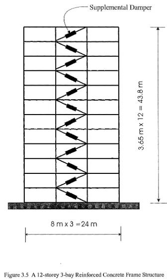
Draft New Zealand Loadings Code, DNZ4203 (Tabuchi, 1992). The supplemental dampers are incorporated into the structure by means of diagonal braces. See Fig.3.5.
The structure with the supplemental dampers will have another dissipation term in the
equation of motion for the structure. Eq(3.l) can be modified as:
[M
]{ii}+ [c]{u}+ {R(u)}+ {Fv(u)}=-[M]{r}iig(t)
(3.4)where {Fn(u)} is the supplemental damping force vector obtained from a suitable
transformation of bracing forces to the corresponding degrees of freedom. {R(u)} is the
nonlinear resistance vector of the original structure (not including the supplemental damping
force) obtained from the addition of individual component's resistance.
The nonlinear time history analysis program RUAUMOKO (Carr, 1996a) developed in the
Civil Engineering Department of University of Canterbury is used for this study. Beam
members and beam-column members are adopted to represent the beams and the columns of
the structure respectively. The inelastic behaviour of a beam and beam-column member
follows the concept of the Giberson one-component model, which has a possible plastic hinge
at one or both ends of the elastic central length of the member. A beam-column member
differs from a beam member in that there is an interaction between the axial force and the
moment yield states.
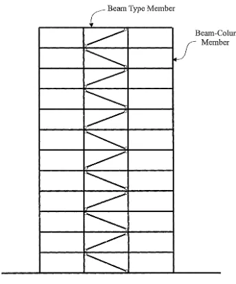
A damping system may consist of a diagonal brace and a damper, and is represented by a
spring type member. This spring type member used here is actually a truss element - only
able to resist axial force, without moment and shear force resistance. See Fig.3.6. The
flexibility of the braces connecting the supplemental dampers to the structure will have influence on the effectiveness of the dampers. First it is assumed that the braces are rigid. The
force-displacement relationship of this damping system is the same as that of the
supplemental lead dampers. The influence of the flexibility of the braces will be investigated
later.
The effect of the supplemental dampers is measured in terms of the supplemental damping
force vector {Fn(u)}in Eq(3.4). There also exists the inherent damping of the original
structure. This inherent damping of the structure represents a dissipation of energy due to
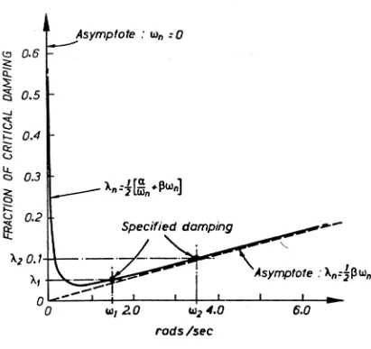
in the structure, cracking of members, the structure's environment (air and water resistance and foundations). This inherent damping can be represented in three ways: viscous damping, hysteretic damping and Coulomb damping. In most applications, the viscous damping model is often used because of its mathematical simplicity. Viscous damping has the property that there is a restoring force proportional to the velocity ( - cu). If a deterministic non-linear time history analysis is used, the most common model is to form the damping matrix by making it proportional to the mass and stiffness matrices, thus
[c]=a[M]+,B[K]
(3.5)where a and
/J
are constants.This model is also called the Rayleigh damping and the constants a and
/3
can be determined as:(3.6)
where {0111 ,
m
1112 are any two natural circular frequencies andt;m1,
<;1112 are their respectivefractions of critical damping. By specifying the damping ratios of any two selected modes, all other modes with natural frequency l'Vti subsequently have their fraction of critical damping given by
(3.7)
as shown in Fig.3.7. In this program it is possible to form the Rayleigh damping matrix based on either the initial structural stiffness or the tangent stiffness.
Elastic
Member
(EI)
Plastic Hinge Spring
Giberson One Component Beam Column Model
Modified Takeda Hysteresis Model
Degrading Bi-linear Hysteresis Model
F
{fr-f)j): (
F-F;
Jf,,
,F_,c;
r-'J
Ko
~
2Fy---L---'t----.-r..---j~6
-Fy
Fy
=
Ellective First Yirld
K0
=
Initial Elastic StiffnessF.
r controls abruptness of loss of stiffness