cosc
460Honours Project Report
Department of Computer Science University of Canterbury
HDLC
A Simulation Model to study the performance of the HDLC protocol.
Supervisor: R. Hunt.
Table of Contents.
1. Introduction • . . • • . • • • . • • • . • . • • • 1 2. Development and Design of Model. • • • • • . . . . 3 2.1 Background Information on the Procedure. 3 2.2 The Model. • • • • • . . • • • . • • . . • • 7
2.2.1 Why Simulate?.
2.2.2 Configuration • • • • . . . • • . 2.2.3 Flow of Data and Control • . • . • .
7 7
. • • 10
3.
4.
5.
6.
2.2.4 Why Simula?.
2.2.5 Simulation Parameters.
2.2.6 A Secondary Aim . • • . . • . . To Use the Model . . . • • • • . . • •
3.1 3.2 3.3
Initialising Parameters . •
Interaction Display . • . • . • • • Report Summary • . • • . Numerical Results • .
4.1 4.2
4.3
The Measurements .
A Discussion of Results • • 4.2.1
4.2.2
Saturated Case • . Non-Saturated Case • Results Conclusion
Further Experiments. 5.1
5.2
Experiments . • • . Extensions to Model • . Summary. • .
References .
. . .
.
.
.
. .
.
.
.
Appendix I - HDLC Program Listing-- i
-. • 11 . • 12 . . 13 . • • 15 . . . 15
. . . . 17
. • 19 . . . 20
. • 20 . • • 21 . • • . 21 . 24
• • • 2 7
• • • 28
• • 28
. . . 29
• • • 30
1. Introduction.
The High-Level-Data-Link Control (HDLC) protocol has been
accepted as an international standard for computer
communications. The International Standards Organization (ISO)
which define HDLC [8,9] contain options and parameters to be
selected according to the environment it is to be used in.
The aim of this project was to produce a Simula program that
will model the ISO HDLC Asynchronous Balanced Mode (ABM)
protocol. This program can be used firstly to provide a tool for
performance evaluation of the HDLC controlled data links and
secondly, to provide more insight into how the various parameters
of an HDLC implementation and the data channel characteristics
influence the performance.
To understand as
common practice to
specific functions
by the layer below.
layer which aims at
distant stations.
well as to design information networks it is
distinguish between several layers where
are implemented by means of services offered
Here we are interested in the data link
controlling the exchange of data between two
It is assumed the two stations are connected by some physical
means that enables the exchange of data bits at a fixed rate.
The exact details of the physical layer(l) are unimportant to the data layer (2).
What is important is that when observed from a higher layer the data link appears to be capable of transmitting data blocks in an orderly and secure way with no loss, duplication or missequencing
occuring in spite of occasional transmission errors at the
physical level.
The presence of transmission errors as well as the fact that a
single data circuit is often time multiplexed on demand between
several data streams, requires both stations to apply the same
rules to delimit bit sequences, to check validity of data, to
organize error recovery mechanisms and so o~. Such a set of rules is called a link control protocol.
A number of data link control procedures have been defined, for
example, ADCCP (Advanced Data Communication Control Procedure),
the national American standard or SDLC (Synchronous Data Link
Control) of IBM. Among the existing link protocols the one which
is gaining attention and the one chosen for this project is the
ISO defined standard called HDLC. HDLC was developed by ISO and
accepted by CCITT and as such the balanced mode is fully
compatible with LAP-B, the second level of CCITT Recommendation
Of the three modes of operation available, the one modelled
here is the balanced class of procedure, applicable to
point-to-point configurations. This procedure is intended for
situations which require equal control capability at both ends of
the link and for use on links carrying heavy traffic. A data
station in this context may be a terminal, a host computer or a
switching node within a packet switching network.
What follows is a description of the HDLC protocol followed by
a discussion of how the model is implemented, how it may be used
and the results obtained from it. Possibilities for further
experiments and a discussion on the use of this model as a
2. Development and Design of the Model.
2.1 Background Information on the Procedure.
For balanced operation the stations at both sides of the link
are called combined stations, which means that information
transfer, commands and responses may take place in either
direction.
commands
---A
I<--
responses>I
BFig 1.
At Layer 2 where HDLC is implemented all transmissions are in
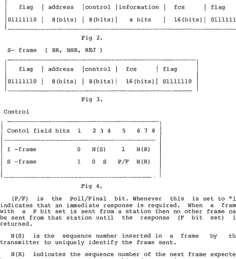
frames and each frame appears as either Fig 2 or Fig 3.
As we are only interested in studying parameters involved with
the transfer of data then it is safe to assume that the link has
already been set up and is available for the time necessary.
Therefore of the usual frames (I->information, S->supervisory,
U->unnumbered) the U frame which is responsible for link
initialisation and clearing down is not implemented. This also
means that frames to handle unknown commands, invalid information fields, unknown responses and so on will also be unavailable.
Therefore the following commands/responses are used: I: Information.
Send information between nodes.
RR: Receive Ready.
Indicate a station has gone from busy to ready. Query a station on its status.
Return an acknowledgement.
RNR: Receive Not Ready.
Indicate a station has gone from ready to busy.
REJ: Reject.
I- frame I )
:flag address !control I information fcs flag 01111110 8(bits) I a(bits)I x bits 16 (bits) I 01111110
Fig 2.
S- frame ( RR, RNR, REJ)
flag address !control fcs flag 01111110 8(bits) I a(bits)I 16(bits)I 01111110
Fig 3. Control
Contol field bits 1 2 3 4 5 6 7 8
I -frame 0 N (S) 1 N(R)
S -frame 1 O S P/F N (R)
-Fig 4.
(P/F) is the Poll/Final bit. Whenever this is indicates that an immediate response is required. When with a P bit set is sent from a station then no other be sent from that station until the response (F bit returned.
N(S) is the sequence number inserted in a frame transmitter to uniquely identify the frame sent.
set to "l" a frame frame can set) is
by the
N(R) indicates the sequence number of the next frame expected by the station transmitting this frame and serves to acknowledge correct receipt of all frames up to N(R)-1.
s
address flag fcs
OO=RR, lO=RNR, Ol=REJ
always of the opposite station. defines the frame boundary.
[image:6.556.51.513.44.550.2]The FCS is used to detect corruption due to random or burst
errors. It is initialised before transmission and checked at the
end of transmission to determine if an error has occured.
Each station has two variables that store the state of the
frames sent and received. V(S) the most recent I frame sent and
V(R) the I frame this station expects to receive next.
The sequence numbering scheme is based on the modulo of a
maximum number. So that all the numbers cycle between zero and a
maximum sequence number.
To send an I frame then it is transmitted with N(S)=V(S) and
N(R)=V(R). After transmitting V(S) is incremented to V(S)+l to
indicate another frame has been sent. If the number of frames
not yet acknowledged by the other station becomes equal to the
window size (parameter-WindowSize) then sending further I-frames
is held until an acknowledgement arrives.
When a station has no more I-frames to send, it can acknowledge
incoming frames by sending supervisory frames either with the
response RR if further I-frames can be accepted, or with the
command RNR if no further frames can be accepted.
If the receiving station has not been blocked for incoming
I-frames, and the FCS is ok, indicating the frame has arrived
free of bit or block errors and N(S)=V(R), indicating the frame
is the next frame this station expects and is not out of sequence
then transmission has been successful, the frame can be accepted
and V(R) can be incremented to V(R)+l.
I-frames can be used to acknowledge reception. If there is not
an I-frame immediately available, the acknowledgement will wait
for a reasonable period of time (parameter-T2) and either
"piggyback" on an incoming frame or leave via a Supervisory frame (RR) created specifically for that purpose.
Any frames arriving with bad FCS's are discarded immediately,
the error being realized by the presence of the next frame to
arrive with FCS intact but sequence number out of order.
Should an out of order sequence number be discovered indicating that somewhere previously an error occured, then a REJ command is
sent indicating to the sending station which frames should be
transmitted. Retransmission starts with the I-frame indicated by
the N(R) count contained in the REJ frame, with the oldest frame
All frames received after the REJ has been issued are discarded
until the frame expected is received. A REJ frame is sent only
once for every group of frames out of sequence. For example
suppose frames 1-7 are sent but frame 1 is an error and discarded
then frames 2-7 are out of order and must also be retransmitted.
The REJ is issued when frame 2 is received correctly with FCS ok
but out of order sequence number indicating to the sending
station that frames 1-7 must be retransmitted. But frames 3-7 do
not trigger a REJ frame they are only discarded.
All frames received with FCS ok have their N(R) fields examined for acknowledgements of previously transmitted I-frames.
If a station should become blocked to I-frames then it sends an
RNR command which indicates receive not ready. The station which
receives the RNR stops sending information frames until it
receives an RR with P bit set which indicates the station is once
again ready to receive. The station sending the RNR discards any
incoming I-frames which are resent latter.
A single I-frame or the last I-frame in a sequence of I-frames
cannot be recovered by REJ. Also, a frame with the P bit set may
be lost. Therefore most implementations introduce a timer as a
more robust method for dealing with errors. Any frames that are
sent restart a timer for a period (parameter-Tl). When a timeout
occurs all unacknowledged frames are retransmitted, similarly to
receiving a REJ. When the last frame sent is acknowledged the
2.2 The Model.
2.2.1 Why Simulate?
Simulation is the technique of representing a dynamic system by
a model in order to gain information about the system through
experiments with the model. It is used to find optimum rules
concerning a systems configuration, to provide a basis for
long-range decision making or to study the behaviour of a system.
The model must be simplified to the point where it has all
relevant details and no irrelevant details. In this sense
simulation is an art as there are no definite rules describing
what is or is not important. After a model has been decided then
it must be verified that the program suitably represents the
model and validated that the model is a true representation of
the real world.
The approach of this study has been different to others made in
this field. In particular to studies found in references [l] to
[6] where the usual approach· has been to undertake a considerable
mathematical analysis and to build a model from this, using
simulation to validate both model and results. The difficulty
with this procedure apart from the rather involved mathematics is
that analytical models tend to be purposeful, resulting in the
study of an aspect or component of the system. As that is not
the intent of this project a simulation model with the aid of
Simula as a programming language has been built. The model is
validated by comparing results from the simulation to the
mathematical results obtained from papers [l] to [6]. The
advantage of this method lies in having a general purpose model
for studying the interaction of numerous paramters of the HDLC
protocol. In addition there is the capability of observing a
display of the relevant parts of the model interacting with
frames and packets. This feature is provided with the aim
towards improving understanding of the HDLC protocol.
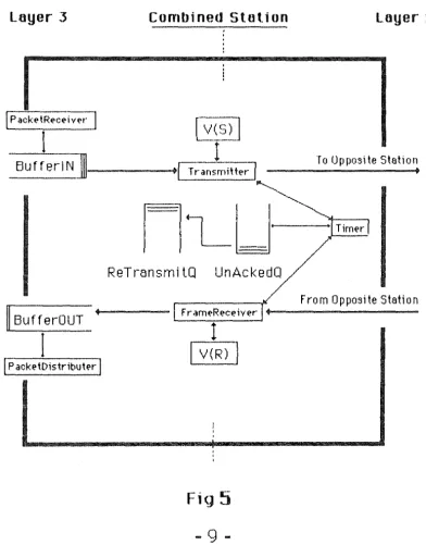
2.2.2 Configuration.
A diagram of the model is shown in Fig 5. The two stations are
connected by a full-duplex transmission link which is
characterized by a bit error probability, propagation delay and
transmission speed. The bit errors are assumed to be
statistically independent however any other error model can be
implemented. It is assumed that all operations occur in zero
time and are not slowed by the processor in which the algorithms
To model error transmissions a single parameter model has been
selected, in which errors are generated according to a Poisson
process. More precisely:
-L/LE
Pr{ one or more errors in a frame of length L}
=
1 - ewhere LE is the mean number of good bits between two erroneous
ones. As pointed out in [2] for suitable paramters, the above
formulae can be simplified to 1-(1-BER)**L which is used in the
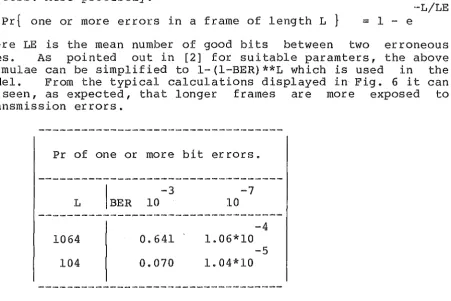
model. From the typical calculations displayed in Fig. 6 it can
be seen, as expected, that longer frames are more exposed to
transmission errors.
Pr of one or more bit errors.
L
1064
104
-3 10
0.641
0.070
Fig 6.
-7 10
-4
1.06*10 -5 1.04*10
As pointed out by J.George and D.Wybux in [l] if the maximum
packet size is 512 and OVERHEAD=40 then the maximum link usage is
512/(512+0VERHEAD)=0.930%. Thus about 7% of the link capacity is
required just to be able to recover from presumably rare
transmission errors.
Errors such as those causing flag destructions have not been
considered. The bits
'O'
which are inserted into HDLC frames inorder to avoid undesirable flag detection have not been taken
into account.
Transmission is not detailed in the sense that the cyclic
redundancy check is replaced by the boolean FCS and a Simula
function DRAW is used to determine if an error will occur in the
transmission of the frame. DRAW accepts as paramters the
probability of returning true and a random number then returns
true or false depending on these values. The probability that a
frame will be in error has been discussed above and can now be
detailed as
FCS := DRAW ( (1-BER)**L, Seed);
where BER is the bit error rate, L the frame length and Seed the
[image:10.556.70.522.49.350.2]Layer 3
Combined Station[Packe~mt]
r-v(_S)
I
I
- BufferlN]---Tr-an-Litter]
~
ReTr-ansmi tQ
UnAckedQ
FrarneReceiYer
II
Buff er-OUTI
I
V(R)!
j
[P
acketDistributer jFig
5
9
-Loyer 2
To Opposite Station
[image:11.560.82.474.145.657.2]2.2.3 Flow of Data and Control.
The flow of data and control at layer
superv1s1on of two processes the framereceiver
The interface between layer 2 and layer 3
processes packetreceiver and packetdistributer.
2 is under the
and transmitter.
is carried out by
The packetreceiver is responsible for placing incoming packets
into BufferIN shown in Fig. 5, and notifying the stations'
transmitter of the packets arrival. It continues placing packets
into BufferIN and notifying the transmitter until it reaches the
maximum buffer space allocated by the user. For most modelling
purposes the upper limit placed on this buffer should be large
enough so that BufferIN will never become blocked. However if it
does block then packetreceiver will not accept any packets until
notified by the transmitter. The transmitter will indicate to
packetreceiver when a new I-frame has been transmitted and
therefore BufferIN has space available to receive more packets.
The packetdistributer is responsible for placing incoming
frames that have been stripped of their overhead bits into
BufferOUT, where it takes care of dispersing these packets to the
layers above. Similarly to packetreceiver, the packetdistributer
process continues to place packets into BufferOUT until it
reaches the maximum buffer space allocated by the user. As
described in section 2.1 when an I-frame arrives but BufferOUT is
blocked then an RNR-frame is transmitted and the I-frame
discarded. As soon as BufferOUT becomes unblocked packetreceiver
notifies the transmitter to send a clear buffer signal which in
turn resumes the flow of incoming frames.
The framereceiver process is responsible for receiving all
frames, removing acknowledged frames from the UnAckedQ, placing
frames into RetransmitQ if a REJ or RNR frame is received and
notifying the transmitter if a reply must be sent. Further
responsibilities involve incrementing the V(R) counter which
indicates the number of frames received and deactivating the
timer when a REJ frame is received, to avoid a double
retransmission. There is no other provision to avoid a double
retransmission when a REJ frame arrives after timeout when both
mechanisms are trying to recover from the same frame loss.
The transmitter process is responsible for sending all frames.
The emission of a frame lasts a simulated time dependent upon the
link characteristics and the length of the frame. Emission also
includes the determination of whether one or more bit errors has
occured.
A copy of each I-frame transmitted is kept in the originating
station until its acknowledgement is received. The buffer or
logical queue these frames are kept in is called the UnAckedQ.
The transmitter ensures that at any time the number of
outstanding frames, which is equivalent to the number of frames
resident in UnAckedQ, does not exceed the window size. When a
UnAckedQ are placed into the RetransmitQ in such a way that the
oldest frame is transmitted first. Frames in the RetransmitQ are
always given priority by the transmitter over packets waiting to
be transmitted from BufferIN.
A typical life cycle of a packet being transmitted between two
stations of this model consists of the following. A packet
arrives at BufferIN, if there are no other packets waiting then
it is transmitted immediately, with a copy being kept in UnAckedQ
for purposes of possible retransmission. If the frame arrives
free of error then it is checked that it is in sequence. If the
frame is carrying an acknowledgement or group acknowledgement
then the relevant frames are removed from UnAckedQ and the
transmitter notified of the frames correct arrival. The overhead
bits are removed from the frame and the packet placed into
BufferOUT for dispersal to the upper layers. If there are no
packets being dispersed and there are no other packets waiting in
BufferOUT then it is distributed immediately. If a bit error has
occured or the error-free frame indicates a previous error then
the frame is discarded and the copy eventually retransmitted.
2.2.4 Why Simula?
Simula is a general purpose language with ALGOL60 as a subset.
The main addition, the class construction in Simula, is used to
define the data structures and operations of independent objects.
Many objects may be generated, co-existing and executing in
quasiparallel,i.e as coroutines.
In Simula a system class SIMULATION establishes a context in
which it is easy to describe processes (both data structure and
operations) and the interaction between processes (both data
interaction and sequencing). Thus Simula is well suited for
modelling the four processes packetreceiver, packetdistributer,
transmitter and framereceiver as described in section 2.2.3. Two
of the system defined classes are HEAD and LINK classes. Any
class prefixed with HEAD has the additional property that it may be used as a list store in which objects of a class prefixed with
LINK may be stored. There are a number of procedures available
as attributes of HEAD and LINK objects. These two classes enable
the simple implementation of buffers Bufferin, BufferOUT and
queues UnAckedQ, RetransmitQ. A complex program involving a
large number of interactions makes the debugger a useful and
efficient tool for debugging.
The simulation was carried out on the University of Canterbury
Computer Science Departments D.G. Eclipse S/130 computer. The
Simula program is designed to be portable to other simula
implementations, however there is one feature that has been used
for readability that is non-standard. The feature ANDTHEN has
been included as part of the Simula compiler provided by the Lund
Institute of Technology. If the expression
is to be evaluated, then e2 is evaluated if and only if el has evaluated to true.
2.2.5 Simulation Parameters.
The model has been implemented in Simula and employs
event-by-event simulation. It can handle symmetrical and
asymmetrical traffic flows and equal or different transmission
speeds in both directions of the full-duplex link. The link is
assumed to be available and operating during the length of the
simulation. The type of transmission is non-selective, that is,
all retransmissions are made in the sequence they were originally sent in.
The user determines the following parameters: .Transmission rate in each direction •
. Propagation delay in each direction •
. Max sequence number of the frame-numbering scheme . • The number of overhead bits carried in each frame • . Bit-error probabilities •
. Window Size. ·
.Length of packets to be transmitted in each I-frame • • Interarrival rate of packets to be transmitted •
• Interdistribution rate of packets to be distributed • . Primary timer •
• Secondary timer .
. Size of the buffer, that packets arrive to • . Size of the buffer, that packets leave from.
The transmission time of a frame is the time between
and end of the same transmission. How fast a frame
transmitted is dependent upon the transmission rate.
example of terrestrial links is a transmission rate of
which enables a frame of 1024 bits plus overhead bits
transmission time of 1024+0VERHEAD/9600.
the start
can be
A typical
9600 bps
to take a
The propagation delay is the time between the start of
transmission to the start of receipt of that frame at the
opposite station. Typically terrestrial links have propagation
delays small enough for zero to be a reasonable approximation,
whereas satellite links usually have more significant delays.
The maximum sequence number of the frame-numbering scheme is
dependent upon the number of bits available in the contol byte
for NR and NS fields. Usually there are three bits which allow a
number to range between O and 7, the maximum sequence number in
this case being 7. It has been left as an option to be specified
by the user in the event that extended mode is used which allows
a numbering scheme between O and 127.
As described in section 2.1 a supplement of information to each
frame is needed in order to make possible the detection of
address, control and fcs fields is called the link overhead and consists of at least forty bits. It is assumed the size of the supervisory frames and the size of the overhead is the same. Similarly to max sequence number this has been left as an option
to the user in the event the extended numbering system is experimented with, which raises the number of overhead bits required to at least 56.
The bit error rate is an indication of the number of errors the user expects from a transmission link. A BER of 0.001 indicates the user expects a single bit error from the physical layer every thousand bits transmitted. It has been discussed above how BER may be applied to determine the value of FCS.
The window size of each station is the number of frames that can be transmitted before the station is blocked and forced to wait for acknowledgements.
Packets, and therefore the data field of Information frames, are assumed to be of constant length. An I-frame in this model can only contain one packet. They are assumed to arrive at each station according to two independent Poisson processes,i.e, The mean time between arrivals c~n be different for traffic in either direction. The system is in a stable state if and only if the rate of arriving packets at each node is less than the maximum throughput. If that were not the case the number of packets waiting to be transmitted would grow indefinitely. Similarly packets are assumed to be distributed from each station according to independent poisson processes. If the distribution rate is less than the maximum throughput and the packets are arriving sufficiently fast, the buffer receiving packets to be distributed soon becomes blocked.
The primary timer is restarted with each frame transmitted. It is the time the sending station will wait for a reply from the other station before assuming the transmitted frame or its acknowledgement has been lost. When this timer times out all frames waiting to be acknowledged are retransmitted.
The secondary timer is restarted when an acknowledgement has to be transmitted. If the acknowledgement has not piggybacked a ride to the opposite station by this time then an RR frame is created to specifically transport the response.
2.2.6 A
Secondary Aim.A secondary goal of this project, apart from being able to evaluate performance of the HDLC protocol is to improve understanding of the system. An option has been included that allows the user to observe individual packets arriving, being transmitted between stations and leaving the system.
arrival of a packet in the system, the distribution of a packet
from the system, the transmission and receipt of a frame. The
display includes the time the event was triggered, the time the
simulation is due to finish, the contents of all buffers from
each station, the event that triggered the display the send and
receive counters of each station. This display can be very
practical for observing the interaction of commands and frames,
and a useful device for finding likely bottlenecks.
If the display option is being used and the interaction of
frames becomes difficult to follow then another option can be
used which allows the user to specify a source and sink file for
each station. If these files are specified then arriving packets
are simulated by the next character from each stations source
file, which is transmitted as a frame and distributed to the
upper layers by writing the character to the receiving stations
specified sink file. Hence the sending of a packet/frame is
simulated by sending a character. If they are not specified the
character assumes the default value of
"*"
An advantage inusing this option lies in assuming the user to be familiar with
the words or characters in the source files and hence more able
to follow the sequence of complicated interactions. This method
also acts as a secondary source of validation. StationA's source
file by the end of the simulation should appear as StationB's
sink file with minor changes. It should be apparent to the user
that the HDLC protocol has worked correctly and despite
occasional transmission errors all the packets/characters have
arrived at the opposite station in the correct sequence and
without loss.
The minor changes in the two files are due to an inherent
feature of Simula that makes it difficult to implement a suitable
procedure to read a line from a file without padding the rest of
the line with blanks. Instead of having extra blanks in the file
it has been decided to have no blanks at all. Thus the sink file
should be a copy of the opposite stations source file without
blanks. This leaves the user with the option of being able to
observe the flow of a single frame through the system.
This option may be useful to further understanding of the
complex interactions involved with HDLC but is usually not used
as a tool for performance evaluation. For most evaluation
purposes the option of specifying a source and sink file and the
option of observing the interactions are left out because of the
extra time needed to run a simulation caused by the significant
increase in I/0. As this option is not used for performance
evaluation the problem of missing blanks in the sink file is of
minor consequence. The usual aim of a performance evaluation run
is to produce the final report summary which contains information
concerning the mean waiting time of frames, the mean transfer
time of frames, the number of I-frames transmitted, received and
3. To Use The Model.
3.1 Initialising Paramters.
To run the program, type HDLC and then
return. The user is then presented with
relating to the configuration of the model. typical display.
press the carriage
a series~~ .. f questions
Figure 5 !presents a
7J
Initialise variables for both stations. Type '0' to obtain the default value'<>':
Max
Sequence Number<?> : >0Simulation Length<lsec> : >100
Do you want a display of the interactions <NO>: >0
Do you want a hardcopy of the interactions <NO>: >l What do you want to call this file? : >TRACE.
What do you want to call the report file? : >REPORT.
Fig 7.
All parameters have an indication of what value should be
provided by the user within the"<>". Whenever a "<>" appears
then this default can be obtained by typing
"O".
Only queriesthat do not have a default option should be answered by typing
anything other than a number.
A number of these parameters have been previously discussed and
will not be described again in this chapter. The reader is
refered to section 2.2.5 on the simulation parameters for the
necessary information. In the above example the maximum sequence
number has been given the default value 7 and the simulation
period is for 100 simulated seconds. The simulation period
determines the length of the simulation run. When source and
sink files are not specified then the simulation period and link
characteristics determine the number of frames that will be
transmitted.
Tpe user has refused the option of observing the display of
interactions. Choosing the default parameter is obtained by
typing a
"O",
choosing any other value for this parameter isachieved by typing any other number. In response to a boolean
yes or no query then the default "NO" is obtained by typing
"O",
any other number typed will have the effect of returning yes or
true to the question. When the question
appeared in the example, the user replied with "YES" by typing a
number other than zero. In response to the users reply the next
question is for the name of the file the trace of events is to be
stored in. Note there is no default value for this.
The aim of each run is usually to gain the final breakdown or
report of what happened during the run, thus the final query
before initialising the parameters of each station is for the
name of the file the report is to be written to.
Next the
format of StationB.
parameters for each station are initialised. The
StationA is exactly the same as the format for
A typical example of initialising StationA follows.
Initialise Station A.
Transmission Rate<9600.0bps> >0
Propagation Delay<O.Osecs> >0
No. of Overhead Bits<40> : >0
Seed<l2345> >123
Bit Error Rate <0.0> : >0.0001
Window Size<7> : >0
Max Information field size<l024> >0
Inter-Arrival rate of packets<O.l> >0.01
Inter-Distribution rate of packets<O.l> >0.01
The primary timer Tl<l.Osec> : >0.5
The secondary timer T2<0.0sec> : >0
Max number of packets in BufferIN<lS> : >0
Max number of packets in BufferOUT<lS> : >0
Do you want a Source and Sink for Packets? <NO> >l
Enter the source file name >SOURCEA.
Enter the sink file name : >SINKA.
Fig 8.
The Seed is used as an input variable for the distribution
functions of Simula. A different random number seed should be
supplied for both stations however the option of repeating the
same default seed for two simulation runs is provided as it is
sometimes useful to recreate a run using exactly the same
parameters. Given the same initial seed and the same
configuration of a previous run the Simula functions will provide the same outcome.
By using the default values to all questions and providing a
file name for the final report the program will run on a default
3.2 Interaction Display
In fig 7 if the user had replied
Do you want a display of the interactions <NO>: >l
then the display of interactions is sent to the terminal. The
display is triggered by the arrival of a packet, the distribution
of a packet and the transmission or receipt of a frame. The
display includes the time the event was triggered, the time the
simulation is due to finish, the contents of all buffers from
each station, the event that triggered the display, the send and
receive counters for each station. As well as the event
indication there is a direction indicator that describes the
direction a frame is travelling, or which station a packet is
leaving from or arriving to.
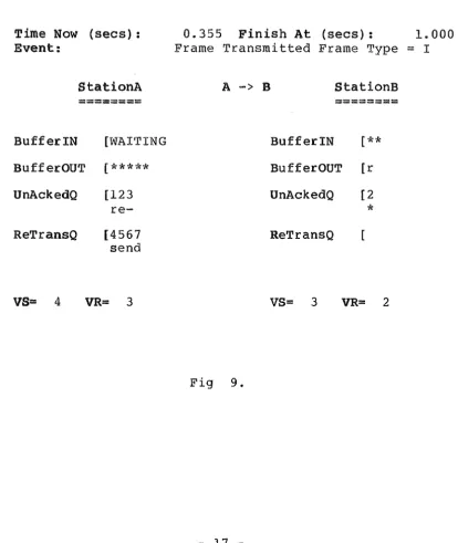
Time Now (secs) : 0.355 Finish At (secs) : 1. 000
Event: Frame Transmitted Frame Type
=
IStationA A-> B StationB
========
========
Buffer IN [WAITING BufferIN
[**
BufferOUT
[*****
BufferOUT [rUnAckedQ [123 UnAckedQ (2
re-
*
ReTransQ [4567 ReTransQ
send
VS= 4 VR= 3 VS= 3 VR= 2
[image:19.557.74.488.220.710.2]In Fig. 9 the frame with sequence number 3 (11
- 11) has just been
retransmitted. The direction indicator 11A -> B11 indicates the
frame is travelling from StationA to StationB. RetransQ and
UnAckedQ also display the uniquely identifiable sequence number
of each frame transmitted.
Other events that may be displayed include the following:
Packet Arrived, Buffer IN
Packet Distributed, BufferOUT
Frame Transmitted Frame Type
=
III II II II RR
II II II II
RNR
II II II II REJ
Frame Received Frame Type
=
III II II II RR
II II II II RNR
II II II II
REJ
StationA is reading packets from a source file whereas StationB
is using the default 11
*
11 to represent packets. StationA has 7packets in BufferIN waiting to be transmitted, 3 frames in
UnAckedQ waiting to be acknowledged and 5 frames in RetransmitQ
waiting to be retransmitted. Frames in RetransmitQ have higher
priority to be transmitted over packets waiting in BufferIN.
StationA also has 5 packets, that have been correctly received
from StationB and are waiting to be dispersed to the upper
layers. StationB has two packets waiting in BufferIN, 1 frame in
UnAckedQ and no frames being retransmitted.
In fig 7 when the dialogue
Do you want a hardcopy of the transactions <NO> >l
What do you want to call this file? : >TRACE.
took place, the user indicated a trace of events should be placed
in a file called "TRACE". The file will appear exactly as it
would on the screen but each event will be one after the other.
This enables the user to review the interactions after the
3.3 Report Summary.
At the end of each simulation run a report summary is provided
which contains the value of parameters provided by the user
including the number of supervisory frames, the number of
information frames transmitted and retransmitted, the number of
I-frames received, mean waiting and transfer times of each
station.
Simulation Length(secs) Max Sequence Number
Transmission Rate Propagation Delay Overhead
Bit Error Rate Window Size
Max Information Field Size Arrival Rate of Packets
Distribution Rate of Packets Primary Timer (secs)
Secondary Timer(secs) Max Size of BufferIN Max Size of BufferOUT
100.0
7
No. of Supervisory Frames Transmitted No. of Information Frames Transmitted No. of Information Frames ReTransmitted No. of Information Frames Received
Mean Waiting Time Mean Transfer Time
Fig 10.
A -> B
---9600.0 0.005 40 0.0001000 7 1000 0.130 0.1001. 000 0.000 15 1000 0 646 216 0
1. 336
1. 619
4. Numerical Results.
4.1 The Measurements.
Two different and important traffic situations are treated.
Firstly the saturated operation where a station always has a
packet waiting to be sent, in this case throughput is the measure
of performance which most appropriately characterizes this mode
of operation. Secondly the non-saturated operation where the
amount of information varies statistically, in this case the most
relevant performance measure is average delay. This is the more
realistic case, it means that transmission channels are not fully
loaded because of delays and throughput is less than the maximum
achievable.
Bux, Kummerele and Troung in [2] have made a similar study
using this concept of monitoring two cases, the saturated and
non-saturated operation. In [l] Georges and Wybux use this idea
to narrow the range of parameters to study by selecting the best
values for the saturated case then applying these values to the
non-saturated case.
In the non-saturated operation Bux, Kummerele and Troung
distinguish average delays into two categories, the mean waiting
time and the mean transfer time. The waiting time is the time
interval from the arrival of a packet in BufferIN to the
beginning of its first transmission. The transfer time is the
time interval between the arrival of a packet in BufferIN and its
correct reception, including potential retransmissions, at the
4.2 A Discussion of Results.
4.2.1 Saturated Case.
Fig. 11 shows the maximum throughput of information bits relative to the transmission rate as a function of the length of the information field in I-frames. The maximum ratio of information throughput to transmission rate when the packet size is 10 and the overhead is 40 is 10/(10+40), which equals 0.2, i.e. the best information throughput obtainable occurs in the presence of zero errors and can be found by the ratio I/(I+OVERHEAD).
Given 10 seconds to transmit the data at 9600bps then the station should be capable of transmitting 10*9600 bits. From one of the simulation runs with these parameters and a bit error rate of 0.001, a total of 1596 frames were transmitted of which there were only 10 information bits in a frame therefore the information throughput was (1596*10bits)/(9600*10seconds) which is approximately 0.166 but significantly less than 0.2. From the graph we can see that bit ertor probabilities equal to or less than 10**-7 start to follow the maximum throughput line found by I/(I+OVERHEAD).
The curves of the graph are typical of systems depending upon retransmissions, and demonstrate how much throughput depends upon the likely error rate. For large bit error rates there is usually a definite maxima, i.e. for this error rate there is a best information field length to ensure maximum information throughput. This is because with short I-fields there is a low probability a frame gets disturbed but the number of overhead bits is relatively high. With a large I-field, the number of overhead bits is relatively lower but the probability of a frame error is higher. These sort of graphs are useful for cost assesments, i.e. it may be worthwhile to improve the current system and to reduce the bit error rate to gain a significant increase in throughput.
Transmssion Rate
=
9600 bps
Propogation Uelay
=
0secs
Window Size
=
7
""'-...
;:1 BEi~ ::: 0
0.
---.c:
1.0 - - - - i ~BER = 1 0- 7
DD
-;::j <l) 0.9
0 ...>
0.8
l.. (,tj
.c:
0::
E-t 0.7
c: c:
0.60 0
. .--,
...
...> (/)
(,tj (/) 0.5
8
...
8
0.4l.. (/)
0
c::
... 0.3
c::
(,tjBER= 1
o-
4 .._... l..E-t 0.2
~
(,tj 0.1
~
BER= 1 0 -3
...
0.0
10
100
1000
10000
I-field length (bits)
-22-'
+-'
:::,
o.
1.0.c:
DD
0.9
::i <l>
0 ..,_)
~ ~ 0.8
.c:
0::f-, 0.7
c:: c::
0 0.6 [image:25.558.67.521.250.651.2]0 . .-1
...
(/)...,
(tj
...
(/) 0.58 8
0.4~ (/)
0
c::
...._.
(tj0.3
c .
~--<,__.
f-,
0.2
ix
~ 0.1
~
0.0
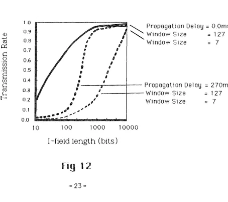
Tnrnsmssion Hate
=
51200 bpsBER = O
secs
,---~~:ii,ii~
~ Pr-opegelion Deley= O.Oms/ 1 " - Window Size = 127
10
, , Window Size
=
7, fl
II 6
I I
,
'
• I
'
'
,,
'
.
'
.
'
1----,.---t---
Propr:igetion
Deley=
270ms,
,/----r---Window
Size=
127/
, /
Window
Size=
7;
.~
.,."'
.
.
,,,
...
_.,.,,,
..
100
1000
10000
I-field length (bits)
Fig 1 2
-4.2.2 Non-Saturated Case.
Fig. 13 demonstrates the effect error rate has on the mean
transfer time. The axis are, -the mean transfer time/
transmission time of an I-frame versus the useful channel load.
The useful channel load corresponds to the portion of total
channel load caused by the successful transmission of information
bits. Transfer time is the time a packet enters the system until
it is correctly received by the other station. Because the
non-saturated case is being considered the channels are only
loaded corresponding to a fraction of their full capacity. The
useful channel load is equivalent to Arrival Rate
*
I-framelength/Transmission rate.
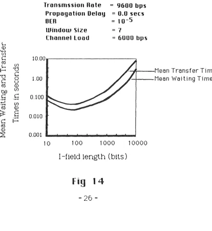
A distinct minima is shown in fig. 14. For small I-field
lengths the number of bits used for overhead is relatively large
and since a large number of overhead bits is necessary to achieve t)'
this throughput. As the I-fields grow larger the relative
overhead size decreases but the block error probability grows,
error recovery takes longer and waiting and transfer times grow
proportionally with the length of I-frames. A comparison with
fig. 11 shows that the shortest delays occur at significantly
smaller I-field lengths than the maximum throughput values.
Presumably the increase of transmission time and block error
probability with growing I-frame lengths outweighs the impact of
Q)
8
...
E-c::
0
...
(/) (/) ...
8
(/)
c::
(.tj Q)
~
E-
s
""
~CJ) ~
8
C.t..,I
...
...
E-~
..
c::
Q) ~
... (/) ...
0
c::
(.tj
~
E-c:
~Q)
::E
10.0
8.0
6.0
4.0
2.0
0.0
Transmssion Rate Propagation Delay Window Size
I-Field Leng th
0.0 0.2 0.4
=
9600
bps=
0.005
secs
=
7
==
1000 bits
...----.--BER"' 10- 4
0.6
/BER= 10-S
ER
=
0.0O.B
Useful Channel Load
Fiq 13
-~ (1)
...,,
(/)c::
~tn
~
!--< '1J
'1J
c::
0c
u~ (1)
uo (/)
[image:28.563.59.495.190.664.2]c:: c::
...
...
...> (/)
...
~ (1)
:3=
...
8
c
!--<~
(1) ~
1.00
0.100
0.010
0.001
Transmssion Rote
=
9600 bp·sPropogotion Deloy = 0.0 secs
BER
=
10-5=
7
UJindom Size
Clrnnnel Load == 6000 bps
10
100
1000
I-field length (bits)
Fig 14
26
---1'1---l"lean Transfer Time. .1-ii--Mean Waiting Time.
- 4.3 Results Conclusion.
From the results, it is apparent that if the relevant
parameters are adjusted to meet the specific needs of the users
then the HDLC balanced class of procedures provides efficient
utilization of the transmission lines with low delays and
transfer times.
A study of the saturated and non-saturated case is the key for
performance considerations. In the saturated case where
throughput is the most relevant consideration, then it can be
shown to have a distinct maxima determined by the length of
I-field and the bit error rate. The window size of satellite
links has a significant impact on throughput as opposed to
terrestrial links where window size has very little impact. With
the non-saturated option, waiting and transfer times show
definite minima determined by the length of I-field and by the
· 5. Further Experiments.
5.1 Experiments.
Only a portion of the performance evaluations that can be
carried out with this model have been demonstrated. What follows
are some ideas for further experimentation with the existing
model. These experiments have not been attempted but the model
has been designed, built and tested to the extent that all of
these experiments are possible.
A detailed experiment could include a study on the performance
of traffic in both directions, and then a study of disymmetrical
traffic where the pararrg:ers for traffic in each direction are
different. It may be shown how a window size of 7 is suitable
for symmetrical traffic but not appropriate under disymmetric
conditions, or how the largest window width of 127 may be
sufficient for packets of reasonable length but short packets
might require a further increase in window size to produce a more efficient throughput.
It has not been discussed what effect changes to the primary
and secondary timers would have. A study on the values of Tl and
T2 is useful in the sense that if Tl is too small then some
frames will be retransmitted for no reason other than a timeout,
creating a deadloop, or if Tl is not small enough this will
result in some inefficiency while frames wait to be
retransmitted. If T2 is too small then an RR-frame will be
created to piggyback the acknowledgement for every frame
received. If it is too large then there is some loss in
efficiency when the opposite station becomes unable to transmit
5.2 Extensions To Model.
Any small changes to the model can be made efficiently because
of the modularity provided by Simula and the relatively simple
queues used to implement the model.
Another possibility for experimentation lies in having a number
of packets being transmitted by a single I-frame. It is assumed
in the model that all packets are of the same length and that
only one packet is transmitted per I-frame. It was decided to
model I-frames in this manner after a number of discussions. The
standards [8] and [9] leave these parameters optional but it
appears that most implementations follow the procedure of padding
packets that are not full with blanks or other such characters.
If a study were carried out on this parameter only, it may
provide useful results. For example a user may discover that a
newly configured model that accepts exponentially distributed
packet lengths and fits any number of packets into the
information field of a frame may find that throughput increases
significantly enough to justify a change in the actual
implementation.
Inter-arrival and inter-distribution times have been modelled
with an exponential distribution. In reality the distribution to
use depends upon the implementation being simulated. Other
- 6. Summary.
A powerful simulation tool for studying the effects and
interaction of a number of paramters of the HDLC protocol is
provided. It has been validated by two methods, firstly by
comparison with results found in other studies that have used
analytical and simulation methods, and secondly by directly
observing the flow of frames and outcome of the interactions. An
indication of how it may be used in practice has been
demonstrated by performing a study of a general configuration.
A weakness of the model is the algorithm used to detect blocked
buffers. When the buffer becomes full an RNR frame is sent and
further received frames discarded until the station sends an RR
indicating it is once again ready to receive frames. It is
possible for the user to initialise a configuration such that
every second frame is retransmitted because of a blocked buffer.
This happens because a station is considered blocked when
BufferOUT is full and unblocked after packetdistributer has
released a packet. Thus it is possible for a station to alternate
between blocked and unblocked. For performance evaluation of
other areas this problem is usually ignored by making the buffer
space large enough so that BufferOUT is never likely to become
blocked. However if a study were to be made in this area then it
would be useful to develop a better algorithm for handling this
situation. Possibly an algorithm that "anticipates" the buffer
filling and delays sending an RR frame until a sufficient amount
of space is available can be implemented.
It has not been possible to demonstrate every use of the model
nor has it been possible to cater for every implementation the
model may need to simulate. Section 5 describes some of the
experiments that can be performed by the model and suggests
·References.
[l] Bux
w.,
Kurnmerele K. and Troung H.L."Results on Performance of Balanced HDLC Procedures." National Telecommunications Conference.
Birmingham Alabama U.S.A. December 1978.
[2] Georges J. and Wybux D.
"A Simulation Study of the Performance of HDLC Controlled Links."
Performance Evaluation 1 (1981) pp 126-138.
[3] Bux
w.
and Troung H.L."High Level Data Link Control Traffic Considerations." 9th International Telecommunications Conference.
Torrenolnos Spain. October 1979.
[4] Labetoulle J. and Guy Pujolle.
"HDLC Throughput and Response Time for Bidirectional Data Flow with Nonuniform Frame Sizes."
IEEE Transactions on Computers. Vol C-30, No.6 June 1981.
[5] Bux W. and Troung H.L.
"A Queuing Model for HDLC Controlled Data Links." International Symposium on Flow Control
in Computer Networks. Versailles. 1979.
[6) Labetoulle J. and Pujolle G.
"Modelling and Performance Evaluation of the Protocol HDLC." Ibid. pp307-320.
[7] Belsnes D.and Bringsrud K.
"X.25 DTE Implemented in Simula." Proceedings Eurocomp. London. 1978.
[8] ISO International Standard IS-3309.
"Data Communications-High Level Data Link Control Procedures-Frame Structure."
ISO-TC97/SC6 Document N2293 July 1981.
[9] ISO Draft International Standard (Dis)4335.
"Data Communications-High Level Data Link Control Procedures-Elements of Procedure."
ISO-TC97/SC6 Document N2290 July 1981.
[10) Tanenbaum A.S.
Bl~:n 1 I\I
SIMULATION BEGIN
CO 1Y11Y1(,,1nt ++++~·++++++++++++++++++++++++++++++++++++
+ + + + + + + + HDi....C
A Simulation Model to study the performance of the HDLC protocol.
Bruce J. McAuley Cict o b0i r :I. 9f\l.1.
+ +
·!·
+
+
++ ·+· + + ·+· +·+··+· ++ +·+·+ + + + +·+· .. 1 .... 1 .. + + + +·+· + +·+·+++·I·++++++++
Tne following is a simulation orogram written in Simula that models an HDLC link. The link is assumed to be available and operating during
the length of tne simulation. Therefore LI-frames which are responsible for link initialising and clearing down are not imolemented.The frames
:i. ·r'1vo l V('it:i ,;;i. r-c-~ I ... info r1Y1,,:1·(; :i. ori.., F<F<""Tf'°1i,~.c:iy to rr~c::0) i vr;,?., F<l\11::< ... t·1:::·:,,1c,y not r<0c<,'1 :i. vc:i
r:,, nd F~EJ ... P0,i J r,:ct •
·r
hF.:1 t y p(,1 of t rr,, 1·"1~01Y1 :i. ~,;,::; :l o ·n i ,,, n cl n ... :s.,a 10,1ct :i. Vf:l ., t l"'lc.\ t :i. i;;; .,all retransmissions are mace in the sequence they were originally sent in. Link oarameters that can be a terec include the transmission rate, propagation delay, and the maximuM sequence number.
The parameters which can be altered for each station are bit error rates, window size, maximuM size of information field, arrival rate of packets to be transmitted, distribution ra~e of
packets to be oistributed to layer 3, primary and seconoary timers, the maximum number of packets allowed in the input/output buffers, and the number of overhead bits carried per frame.
l:::.ac 1·1 run
contE,i.:i.ninq a
O f t i·'l E·~
l51..\1Y11Y1i';\ l''Y Of
D l"O(;:J ri:',\1Y1
the simulation providinq the number of frames transmitted and rece1vea,
retransmitted, a copy of tne parameters provided ano transfer times.
soecifieci by the user information including the number of frames and the mean waiting
For further details refer to the honours reaort ano aooend1ces.
Fff~(ii.._ bi 1Y1T :i. 1Y1E)
I i\lT i:~:(3E t< 8e1q No iYli::1 ><
TEXT ARRAY Screen(0:19)
INTEGER Screen8ize
I I\ITEGE: H
n ., [:
I i\iTEGE F< J
F< F:<
BOOLEAN PrettyPics
DCJUI...EHI\I D :i. 1;c;p l i:~yP :i. ct u r'Eei;;;
REF ( OUTFILE > ScreenEcho;
BOCJLEAN HardCopy ,
~~~ OUTFILE > ReportFile;
Comment Length of simulation Comment Max Sequence Number
c:; o 1Y11Y1<'!lnt T (;,) r'1Y1 :i. 1,"1,::1 :1. ,,, nd ci (·:,,:· b uq 1 n f' o Comment Terminal depth
Comment Global station aociresses Comment Information
Comment Reaay-to-F<eceive Co1Y11Y1G)'r"1t F:<€0 J E·:ct
Comment Not Reaay-to-Receive;
Comment True displays interactions; Comment True displays to user
Comment File of interactions
t<i:::. I"'
'f :i. 1Y1t~O I..\ t :i.
T :i. IYI E'! Cl l..l t ::;::
i:::. ;:,\ c i ( f?.· t 1:< ,,,,, c f'l :i. v (·,~ r
AT :i. 1'(1E)Ci 1J t :i. i'~(::O f '/
nT
i 1Y1i"'Ci ut 2 i~i'2 f' '/APacketReceiverRef,
H'T :i.1Y11':·:U ut :I. He· f'
BT :i.1Y11~C) 1J t:? ::~L,) f
8PacKetRece1verRef
REF HDLCStation) StationA. StationB;
CoMment:******** CLASS HDLCStation ******************************;
CLASS HDLCStation (Address); INTEGER Address;
DEC:J I 1,1
CO 1Y11Y1E:nt An HDLC station is responsible for receiving data :i.n
packets and transMitting inforMatian in frames to tne opposite
station. The station ensures that when ooserved from a higher
layer the data linK appears to be capable of transMitting
frames in an orderly and secure way with no loss, duplication
or missequencing occuring in spite of occasional transMissinn
Ei r l"·O l''~,; at t ne:~ pnyc:; i Ci,,\ l 11::::V(,J 1. ;
1·'<i:::.l···
Rei:::· Bu 'i'ff? i"iJUT
.
'I 1-(l:::.I· .. H1::::AD HEJHJ Ht:::r:~D HEnD
RE· Tr,,\ nr:~ 1Y1 i t C'! ; Un(:)c I( G:•O (:.;\
REAL TransmissionRate;
REAL PropagationDelay;
I NT1::::c)F R ClV(':! l'' he,:,\d
I l\iTE:UE:: H i3r,:E'C:i
C 01Y11Y1E:nt
C; () !YI !YI (·:CJ)·'\ t
Co1Y1fr1E:nt
C O 1Y1 !YI ii.·,• )·"1 t
Arriving packets in this
Q;
Leaving packets in this Q :
Frames to be retransmitted;
Frames ~o be acknowieciged ;
CO 1Y11Y1 (:'.) \·') '(; I.. .. l \'"! C·:·:· t )'' <'.':\ l"'I t:; 1Y1 :i. !3 s, :i. (:) l"l 1,:; UC! E:• C CoMMent One way aelay
CoMment flags, fcs,acdress,control; Comment Random numoer seed
REAL ArrivalRate
RERL DistributeRate; l<EnL .. DEF<
Comment Mean interarrival rate of aa~kets;
CoMment Mean rate of packet distibution Comment Bit Error Rate;
H1:::.1 .. H ... T:i.
1·<1:::.r-.. )L. T2
INTEGER WindowSize
Ii,ITE(3EF< Vi::;.,
\m;
I i\lT[C)E ,:~ !\IE:·)>< t TO E<E·::nc /.,; f::·!CI :.:
BOOLEAN TransMitReJ
F<t0.J T l''t:\l''l!,"-1Y1 :i. t t (\?.•cl
T r ,::·1 '(l r:,, (1 c k
13 r'cnH in I(
BOOLEAN TransmitRnr
1:~ n l" T r' ;;,1 n i::; 1Y1 :i. t t <'!:' c:I
br,11··1dB u f f r'! r·1:::·1..111
INTEGER MaxFrameSize,
E<uffr;;irINMa>< .,
B1..1. ff f? r·UUTIYi,;}.>< !;
F<EF
F<E~:r:·
II\W'IJ....E
UUTF I L .. i:::
n
Ci u rcE-,1F i 1 €,:·;.... .
,
.... "l::i :1. 'r'\I( ··· l .I. f::
INTEGER SFramesTransmitted, IFraMesTransmitted,
[ 01\'11\'1f)'r"lt
·r
i. !Y1(? rCo1Y11Y1c:.int !':k,•1 ~onrii-.\ rv T :i.1Y11:+: \'';
CoMMent Window Size
Comment Send state variaale ComMent Receive state var1abie
CoMMent A REJ needs to be transmitted;
CoMMent A REJ has been transmitted
Comment Transmit an AcKnowledgement
C o 1Y11Y10,1 ·r'i t b o u. r cf::: ici. ·n d E; :i. n 1 ( s;; J::l 1::·:i c :;, f :i. C·'i! d
Comment A RNR needs to be transmitteo;
Comment A RNH has been transmitted
CoMMent Ou.tput is temporarily blocKeci;
Co1Y11Y1f'~'r'lt IY1i:':\ }( ~ij. i ~·:: E::, C) f t 1"'1(-:;) f l''<:\(\'IF:! Cli:':\'i:; i:~ f
CO 1Y11Y1E1nt: iYIE1)( r::; :I. :~·:~ E~ (:) f Duffc?r I N C'!
CO IYI IYI f,' n t t\'U:':\/( ~:'.; :i. ~~:.: (<:.;! 0 f EJ1..1.ffc::,) r'UUT ()
Comment File of ano data to be sent; ComMent Fi:1.e of received oata
:i.e 1
C:: Cl 1Y11Y1 €:·! 'r"1 t i\l O " () f i;;; l.l [.:) E~ l' \/ i S C) r· y f \"• ii:\ IYI 0:·! 1::; ~?, ,·::·:'1'1 t :; ComMent No. of information frames sent;