399
©IJRASET: All Rights are Reserved
Improving Indoor Air Quality through HVAC
Design in Hospital Building
Khaja Ehtesham Uddin1, Raza Ahmed Khan2 1
M.Tech, 2Associate Professor, Mechanical Department, JNTUH, NSAKCET, Hyderabad
Abstract: In this project the main objective is to design a HVAC system for a hospital building, with focus on supplying treated fresh air, providing comfort to doctors, medical personals and patients. This project also portrays and reveals thermal specialized parameters of the hospital to appropriate type of equipments for HVAC system.. The purpose of my project is to design a treated fresh air system to improve an indoor air quality of an air-conditioning system. Some of the exceptional system and standards are as follows: treated fresh air system, Konnex system., UVC system., and ASHRAE, ISHRAE, ASHE, NABH ,WHO and IGBC standards. Equipment selection and layout of accessories such as indoor and outdoor units of the plan, heating load will be calculated on hourly analysis program(HAP), duct estimating on duct sizer , pipe estimating on pipe sizer through Mc Quay, the motivation of this project is to give architects, engineers, health care providers, facility administrators and associated with designing health care facilities with a complete set of guidelines.
Keywords: HVAC System, Infection Control System , ICU, Isolation Room, Ventilation, AHU, Hospital Building, HEPA filter, Filters, Air Curtains, KNX, TFA, UVC, Telerobotic.
I. INTRODUCTION
The term HVAC refers to Heating, Ventilation and Air Conditioning, has a wider scope. It deals with the units used in applications like comfort heating, cooling and ventilation or heating and cooling applications in residential and commercial areas. It includes study of wide range of equipments from small scale domestic application to the large scale industrial applications. Advance and better air-conditioning system is a major objective nowadays with the advancing human requirements. Awesome improvements have been made in the field of HVAC, yet the extent of further researchers are still in exists.
II. INDOORAIRQUALITY
IAQ is characterized as the path towards giving air which is acceptable all around and does not cause negative wellbeing impacts, ailment or ailment in people and is without dust , smalls , drafts and commotion as much as possible.IAQ in healing centre is more basic as the patients have less insusceptibility. In an ordinary healing centre the level of airborne irresistible contaminant increments proportionately with the expanded populace thickness of contaminated people. In this manner IAQ idea in doctor's facility is rising as an advanced field of specialization among designers and human services proficient. Air quality at healing centres needs exceptional insurances amid plan and upkeep stage to keep diseases from spreading.50% of sicknesses are either caused by, or disturbed by , dirtied indoor air. The particular necessities for ventilation and filtration to weaken and evacuate sullying as smell, air-conceived small scale living being and infections, and unsafe synthetic and radioactive substances
A. Conventional treated fresh air units
400
[image:2.612.165.439.76.274.2]©IJRASET: All Rights are Reserved
Fig. 1 Fresh Air Unit
B. Fresh Air Recovery Wheel Unit
The enthalpy wheel is a cylinder, usually 4 to 10 inches deep, packed with a heat transfer medium that has numerous small air passages, or flutes, parallel to the direction of airflow. Commonly referred to as the honeycomb matrix. The surface area exposed to airflow in a wheel lies between 300 to 3300 m 2 /m3 , depending upon the configuration. In a typical installation, the wheel is positioned in a duct system such that it is divided into two half moon sections. Stale air from the conditioned space is exhausted through one half while outdoor air is drawn through the other half in a counter flow pattern. At the same time, the wheel is rotated slowly (2 to 20 RPM). Sensible heat is transferred as the metallic substrate picks up and stores heat from the hot air stream and gives it up to the cold one. Latent heat is transferred as the medium condenses moisture from the air stream that has the higher humidity ratio through adsorption by the desiccant (with a simultaneous release of heat) and releases the moisture through evaporation (and heat pick up) into the air stream that has the lower humidity ratio.
Fig. 1.2 Fresh Air Heat Recovery
III. BUILDINGDETAILS
[image:2.612.125.494.439.589.2]401
©IJRASET: All Rights are Reserved
[image:3.612.71.559.224.330.2]and around 700 spaces are considered while outlining a cooling system. The rest of the zone of the building where aerating and cooling isn't given incorporates spaces like store rooms, AHU room, stair case, latrine segment and different zones. Though, the can area is given a committed ventilation system for guaranteeing appropriate fumes or keeping up vital conditions and this ventilation system is outlined by the standard standards. The greatest inhabitancies of this building ranges up to around 205 people for every each floor and the quantity of tenants that can be suited inside each floor is evaluated from the ASHRAE standard that determines around 25 square feet for every individual. A vital thought in this viewpoint is, the quantity of tenants is chosen in view of the zone to be aerated and cooled and not the aggregate building territory, thus the above expressed scope of inhabitancies is chosen for the ventilated region.
Fig. 2 Building Plan
IV. CALCULATIONS&RESULTS
A. Heat Load Calculation
The heat load calculation is done using hourly analysis program (HAP) software. The net heat load estimated for the specified building is 670 T.R and for each floor the heat load is 67 T.R. The maximum air flow rate obtained in terms of cubic feet per minute for each floor is 23400 CFM.
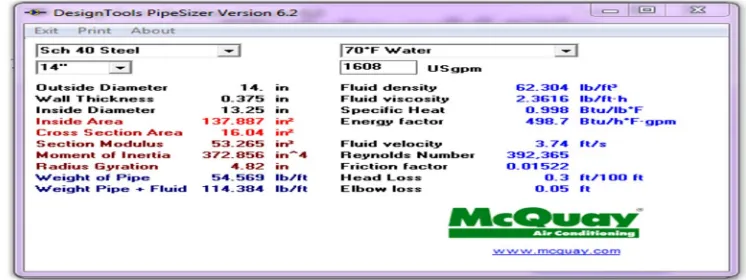
B. Pipe Sizing
The cooling water pipe sizing is done using the software named pipe sizer developed by Mc Quay. The main consideration or the input parameter in the design of cooling water pipe size is the water consumption rating. The water consumption rating for chilled water system between 2 gpm and 3 gpm per TR based on the load of the building.
Water consumption rating – 2.4 gpm per TR for closed cycle Total gpm required = 670 × 2.4 = 1608 gpm
Gpm for each floor = 67 × 2.4 = 160.8 gpm Pipe size obtained from calculation = Ø 14”
[image:3.612.106.479.585.725.2]402
©IJRASET: All Rights are Reserved
C. Cooling Tower Sizing
Water consumption rating – 3gpm/tr for cooling tower cycle. Friction loss –upto 2.5 ft /100ft for commercial systems. 1TR = 3gpm.
Total TR of the building = 670 TR (heat load) Total gpm required = 670x3=2010 gpm. Pipe size obtained = 14” Diameter.
H.P = GPM x TOTAL HEAD
3960
Total head = static head + pressure head + friction head + velocity head static head = 156’
velocity head = 1.75’
pressure head = 156-5 = 151’(10%) = 15.1’ friction head = considering major valves 3-butterfly valves-3x110 = 330m 3-motorized valves – 3x 47 = 141m 3-Y strainer – 3x56 = 168m 20- 90 bend – 20x 2.2 = 44m 683m 2240ft(15%) friction head = 336’ Total head = 156+1.75+15.1+336 = 508’
H.P = 2010 x 508 3960 H.P = 258 H.P
[image:4.612.46.495.40.649.2]258(15% Factor of safety ) H.P = 297 H.P
Fig. 3.2 Pipe Sizer
D. Estimation of Cost Water cooled chiller system
Initial cost = ₹ 35000 per T.R = 35000 x 670 ₹ 23450000
Pump cost = ₹ 10000 x 12 (25 HP – 12 No’s) = ₹120000
403
©IJRASET: All Rights are Reserved
Operating costs
Chiller = 670 x 0.65 kW = 436 kW
Total energy consumption = 436 x 24 x 30 = 313920 units / month Cost = 313920 x ₹10 = ₹3139200
Pump = 300 HP = 300 x 0.746 = 223 kW
Energy consumption = 223 x 24 x 30 = 160560 units / month Cost = 160560 x ₹10 = ₹1605600
Total operating cost = ₹4744800/ month
E. Results
In this project an improving of IAQ through HVAC design for hospital building is design with treated fresh air system. Treated fresh air units are installed in hospital building before an Ahu unit for the requirement of fresh and uncontaminated air which is required to supply in different regions of hospital building. The higher the occupancy in the hospital building the higher chance of getting CO2 levels in the premises. Each occupant requires 0.65cu.m of oxygen/hr. in normal condition and produces the CO2 levels of around 0.2cu.m. When the carbon content increases it creates difficulty in breathing and causes suffocation problem to the occupants. Thus the system is designed in such a way that the % of CO2 levels should not exceeds its range, by installing treated fresh air units in HVAC system to improve an IAQ.
Operation Theater
S.NO PARAMETRES SPACES LIMIT/RANGE REFERENCE INST.
1 Temperature O.T 16°C - 22°C ASHRAE 55-2010 IAQ Calc
2 R.H O.T 30% - 50% ASHRAE 55-2010 IAQ Calc
3 Air Movement O.T 0.6ft/s - 0.24m/s WHO ISO 7730 IAQ Calc
4 Ventilation(ODA) O.T Depend on type of activity ASHRAE 62.1-2010 IAQ Calc
5 Ventilation(CO2) O.T < 700ppm ASHRAE 62.1-2010 IAQ Calc
6 Ultrafine particles O.T < 1.0micron NABH IAQ Calc
7 Carbon Monoxide O.T < 6ppm ASHRAE IAQ Calc
AMCU
S.NO PARAMETRES SPACES LIMIT/RANGE REFERENCE INST.
1 Temperature AMCU 20°C - 24°C ASHRAE 55-2010 IAQ Calc
2 R.H AMCU 30% - 60% ASHRAE 55-2010 IAQ Calc
3 Air Movement AMCU 0.65ft/s -
0.20m/s
WHO ISO 7730 IAQ Calc
4 Ventilation(ODA) AMCU Depend on type
of activity
ASHRAE 62.1-2010 IAQ Calc
5 Ventilation(CO2) AMCU < 1000ppm ASHRAE 62.1-2010 IAQ Calc
6 Ultrafine particles AMCU < 0.8micron NABH IAQ Calc
7 Carbon Monoxide AMCU < 7ppm ASHRAE IAQ Calc
GENERAL WARD
S.NO PARAMETRES SPACES LIMIT/RANGE REFERENCE INST.
1 Temperature G.WARD 20°C - 24°C ASHRAE 55-2010 IAQ Calc
2 R.H G.WARD 30% - 60% ASHRAE 55-2010 IAQ Calc
3 Air Movement G.WARD 0.65ft/s - 0.20m/s WHO ISO 7730 IAQ Calc
4 Ventilation(ODA) G.WARD Depend on type of activity ASHRAE 62.1-2010 IAQ Calc
5 Ventilation(CO2) G.WARD < 1000ppm ASHRAE 62.1-2010 IAQ Calc
6 Ultrafine particles G.WARD < 0.8micron NABH IAQ Calc
404
©IJRASET: All Rights are Reserved
V. CONCLUSIONS
Aim of my project is designing a HVAC system for a hospital, with focus on enhancing IAQ, providing clean and treated fresh air, providing comfort for doctors, medical menials and patients. It also depicts and reveals thermal-technical parameters of the hospital to choose appropriate equipment for HVAC system. This project clarifies the method of controls, monitoring and communication utilizing KNX based control system. HEPA filters is the main segment in designing hospital building. Overall, this project presents definition of thermal properties, overview of hospital building. It also present HVAC system and its components. A complete design for an improving indoor air quality of air using treated fresh air system is presented under this project work and the following results were obtained during the course of this project. The net heat load evaluated for the predefined building is 670 T.R and for each floor the heat load is 67 T.R. The maximum air flow rate obtained in terms of cubic feet per minute for each floor is 23401 CFM. The chilled water pipe size is obtained as 14 inches in diameter corresponding to the total water consumption rating of 1608 gpm. The cooling tower water pipe size is obtained as 14 inches in diameter corresponding to the total water consumption rating of 2010 gpm. The pump capacity determined corresponding to a total head of 144 feet is 25 H.P. A water cooled chiller of capacity about 335 T.R is employed as an auxiliary system. The control of temperature, relative humidity, air movement,CO2 and CO levels are maintained
according to the required specification using IAQ calc instrument in various spaces of hospital building.
REFERENCES
[1] Jay Egg, Brian Clark Howard, “ HVAC SYSTEMS”, McGraw Hill Publications, 2010 Ed
[2] ASHRAE. ASHRAE Handbook - 2001 Fundamentals. Atlanta, GA: American Society of Heating, Refrigerating and Air-Conditioning Engineers, Inc. [3] ASHRAE Handbook (2007) - ‘Heating, Ventilating and Air-Conditioning – Applications’.