421
©IJRASET: All Rights are Reserved
Karnataka, India1
Abstract: In this paper, a novel design of inset-fed rectangular microstrip antenna is simulated, designed and optimized to get a Hexa-band operation frequency. The antenna top portion consists of a L-shaped slit loaded rectangular radiating patch and a H-shaped slot is loaded in the ground plane. This antenna is resonates at six different frequencies of 1.5 GHz, 2.4 GHz, 4.3 GHz, 5.5 GHz, 7.9 GHz and 9 GHz with -10 dB return loss having impedance bandwidths of BW1=13.33%, BW2=5% , BW3=6.5%, BW4=6% , BW5= 4.9% and BW6= 15.6%. The proposed antenna is fabricated on commercially available low cost FR-4 substrate with relative permittivity of 4.4 having physical size of 40 × 30 × 1.6 mm3. The antenna produces broadside nature radiation pattern with maximum gain of 5.68 dB. The antenna finds applications in GPS, WLAN and X-band communications. Keywords: Hexaband, L-shaped slit, GPS, WLAN,
I. INTRODUCTION
Microstrip antenna was first introduced in 1970 and from there the technology becomes the most rapidly developing in the field of wireless communication because of their many tremendous features and advantages [1]. The main advantages of microstrip antennas which increases the interest of researchers in this field are due to its low profile, low cost, compact size, ease of fabrication, installation etc., [2]. Microstrip patch antennas are extremely compatible in hand held devices such as cellular phones and pagers [3]. Due to increased demand of wireless communications, the need of compact microstrip antenna with dual and tri-band characteristics and the antenna with multiband characteristics also increased [4]. To achieve these multiband characteristics of microstrip antenna, many efforts have been made by the researchers in recent years. The techniques such as loading of notches, slots, slits, fractal structures etc., are used to design multiband antennas [5-7]. By introducing these different types of methods and techniques in the geometry of microstrip patch antenna and proper selection of feeding technique helps to achieve the multiband characteristics easily [8]. A multiband characteristic helps the antenna to be used in various wireless applications such as Wi-Max (World Interoperability for Microwave Access) frequency band ranges 2.5 GHz (2.5-2.69 GHz), 3.5 GHz (3.4-3.69 GHz) and 5.8 GHz (5.25-5.82 GHz), WLAN (Wireless Local Area Network) frequency band ranges 2.4 GHz (2.4-2.48GHz), 5.2 GHz (5.15-5.35 GHz) and 5.8 GHz (5.725-5.825 GHz) and Bluetooth at 2.4 GHz [9-11]. On the other hand, microstrip patch antennas with printed slots fed by different feeding techniques have several advantages over conventional microstrip patch antennas. Slotted patch antenna exhibits low radiation loss, low dispersion and wider bandwidth as compared to conventional microstrip patch antenna [12-14]. Also, research attention is focused in the field of radio frequency identifications and microwave energy harvesting since they reduce the number of antennas and space usage [15]. In this paper, we propose multiband (Hex) antenna. The details of the antenna design, simulation and experimental results are discussed in the next section.
II. ANTENNA DESIGN
The geometry of the proposed hex-band antenna is shown in the Fig. 1. The antenna geometry is printed on 40 × 30 mm2 a commercially available low cost FR-4 epoxy substrate of dielectric constant of εr = 4.4 with thickness of h = 1.6 mm. The antenna
consist of a rectangular radiating patch with L= 40 mm and W= 30 mm which is fed by simple 50Ω inset-fed microstrip line of feed length Lf =17.18 mm and Wf = 3.17 mm on the top surface of the substrate and bottom of the substrate ground plane is used. Good
impedance matching is achieved between radiating patch and 50Ω microstrip line by optimizing an offset width of IW = 1.53 mm
422
[image:2.612.134.490.83.290.2]©IJRASET: All Rights are Reserved
Fig.1. Geometry of the proposed hex-band Inset-fed rectangular microstrip antenna
Further, to achieve hexa band operation, optimized L-shaped slit is inserted on radiating patch with LW=6.8 mm, Ll=20 mm and a H-shaped slot in the ground with HL= 7 mm HW=0.5 mm Hd=3 mm. The proposed antenna model is designed by using commercial available Ansys HFSS electromagnetics simulation tool [16]. The optimized antenna dimensions are given in Table I.
Antenna
parameters W L R Wf Lf IW IL h Ll Lw HL Hw Hd
Dimensions (mm)
40 30 11.5 3.17 17.18 1.53 5.98 1.6 20 6.8 7 0.5 3
III. RESULT ANT DISCUSSION
[image:2.612.170.480.530.713.2]The impedance bandwidths over return loss less than -10dB for the proposed antenna is measured. The comparison of simulated and measured frequency versus return loss characteristics of hexa-band rectangular microstrip patch antenna is shown in Fig. 2. From the figure, it is clear that the antenna is resonating at six different frequencies 1.5, 2.4, 4.3, 5.5, 7.9 and 9 GHz with return loss of -10dB having impedance bandwidths of BW1=13.33% , BW2=5% , BW3=6.5% , BW4=6% , BW5= 4.9% and BW6= 15.6% respectively.
423
©IJRASET: All Rights are Reserved
(a) (b)
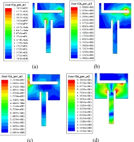
[image:3.612.182.445.134.413.2](c) (d)
Fig. 3. Simulated surface current distributions of the proposed hexa-band antenna observed at (a) 1.5 GHz, (b) 2.4 GHz, (c) 4.3 GHz (d) 5.5 GHz
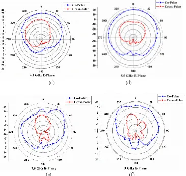
The typical radiation patterns of E-plane co-polar and cross-polar of the proposed antenna is measured at their resonating frequency and is depicted in Fig.4. The figures indicate that the antenna shows nearly linearly polarized and broader side nature radiation characteristics.
424
©IJRASET: All Rights are Reserved
(c) (d)
[image:4.612.129.494.79.425.2](e) (f)
Fig. 4. Typical E-plane co-polarization and cross- polarization radiation patterns of the proposed antenna measured at (a) 1.5 GHz, (b) 2.4 GHz, (c) 4.3 GHz, (d) 5.5 GHz , (e) 7.9 GHz and (f) 9 GHz
IV. CONCLUSION
In this paper, a hexa-band inset-fed rectangular microstrip antenna with L-shaped slit on radiating patch and H-shaped slot in ground is discussed. At each resonating frequency point, a moderate bandwidth is achieved. The proposed antenna has broadside nature radiation pattern characteristic with maximum gain of 5.68 dB. Hence, the proposed antenna is simple in construction and with low cost substrate material. This antenna may finds application in GPS, WLAN, and X-band communications.
V. ACKNOWLEDGEMENT
The authors would like to express their sincere gratitude the authorities of Dept. of Science & Technology (DST), Govt. of India, New Delhi, for sanctioning the Vector Network Analyzer (VNA) to the Department of Applied Electronics, Gulbarga University, Gulbarga under the FIST project.
REFERENCES
[1] P. P. Chandran and S. Viswasom, “Gain and Bandwidth optimization of Novel Microstrip Patch Antenna,” Fourth International Conference on Advances in Computing and Communications, IEEE, pp. 315-318, 2014.
[2] ] V. V. Reddy and N. V. S. N. Sarma, “Triband circularly polarized Koch fractal boundary microstrip antenna,” IEEE Antenna and Wireless Propagation Letters, Vol. 13, pp. 1057-1060, 2014.
[3] S. Behera and D Barad, “A novel design of microstrip fractal antenna for wireless sensor network,” International Conference on Computation of Power, Energy, Information and Communication, pp. 470-473, 2015.
[4] D. Kumar, M. Sharma and S. Bansal, “Novel design of key-shaped fractal antenna for UWB applications,” IEEE 6th International Conference on Computational Intelligence and Communication networks, pp. 87-91, 2014.
425
©IJRASET: All Rights are Reserved
Innovations in Information, Embedded and Communication Systems (ICIIECS), 2015.
[13] M. Rahimi, A. Keshtkar, F. B. Zarrabi and R. Ahmadian, “Design of compact patch antenna based on zeroth-order resonator for wireless and GSM applications with dual polarization,” International Journal of Electronics and Communications (Elsevier), pp. 163-168, 2015.
[14] B. Roy, A. Bhatacharya, A. K. Bhattacharjee and S. K. Chowdhury, “UWB monopole antenna design in different substrate using sierpinski carpet fractal geometry,” IEEE 2nd International Conference on Electronics and Communication System (ICECS), pp. 382-385, 2015.
[15] Si, L. M., W. Zhu, and H. J. Sun, “A compact, planar, and CPW-fed metamaterial-inspired dualband antenna,” IEEE Antennas Wireless Propagation. Letters, Vol. 12, 305–308, 2013.